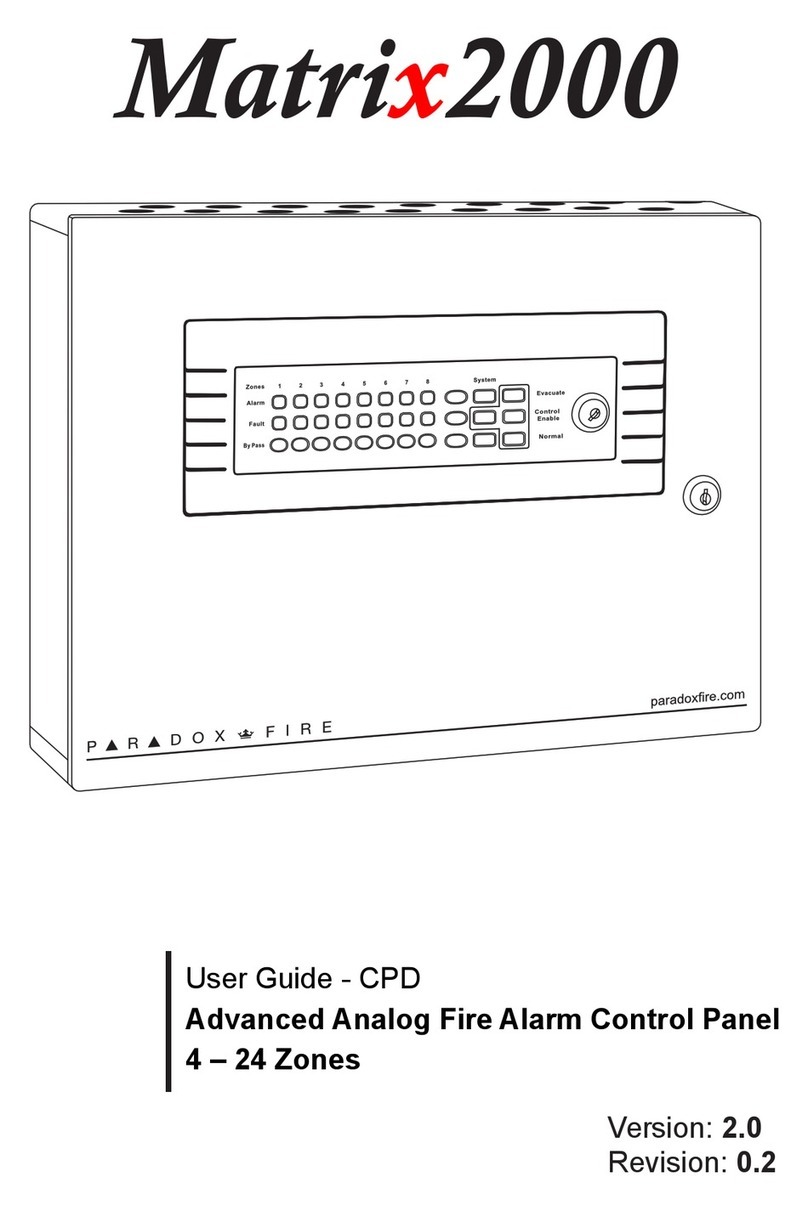
Paradox Digiplex EVO192 User manual

Fire and Burglary Alarm System
EVO192
Installation Guide

Warranty
For complete warranty information on this product, please refer to the Limited Warranty Statement found on
the website www.paradox.com/terms. The terns and conditions are subject to change without notice, from
time to time, in Paradox’s sole discretion. We invite you to visit our website on a regular basis for the latest
Limited Warranty Statement. Your use of the Paradox product signifies your acceptance of all warranty terms
and conditions. Please ensure that your use of the Paradox product is in compliance with local, national, and
international laws.
© 2014 Paradox Security Systems Ltd. All rights reserved. Specifications may change without prior notice. US,
Canadian and international patents may apply. Paradox Insight and Paradox are a trademarks or registered
trademarks of Paradox Security Systems (Bahamas) Ltd. or its affiliates in Canada, the United States and/or
other countries.
This product is manufactured in Canada.
Paradox
780 Industrial Boulevard
St-Eustache, Quebec
Canada, J7R 5V3
Tel: (450) 491-7444
Fax: (450) 491-2313

EVO Installation Guide 3
Table of Contents
Table of Contents . . . . . . . . . . . . . . . . . . . . . . . . . . . . . . . . . . . . . . . . . . . . . . . . . . . . . . . . . 3
Chapter 1 Introduction . . . . . . . . . . . . . . . . . . . . . . . . . . . . . . . . . . . . . . . . . . . . 11
1.1 EVO192 – Residential Fire and Burglar Alarm and Commercial Burglar Alarm Sys-
tem 11
1.2 Features of EVO192 Controller . . . . . . . . . . . . . . . . . . . . . . . . . . . . . . . . . . . . . . . . . . . 11
1.3 Minimum Configuration . . . . . . . . . . . . . . . . . . . . . . . . . . . . . . . . . . . . . . . . . . . . . . . . . 12
1.4 System Operation . . . . . . . . . . . . . . . . . . . . . . . . . . . . . . . . . . . . . . . . . . . . . . . . . . . . . . . 12
Chapter 2 System Installation . . . . . . . . . . . . . . . . . . . . . . . . . . . . . . . . . . . . . . 13
2.1 Safety Warnings . . . . . . . . . . . . . . . . . . . . . . . . . . . . . . . . . . . . . . . . . . . . . . . . . . . . . . . . . 13
2.2 Location & Mounting . . . . . . . . . . . . . . . . . . . . . . . . . . . . . . . . . . . . . . . . . . . . . . . . . . . . 13
2.3 Recommended Installation Procedure. . . . . . . . . . . . . . . . . . . . . . . . . . . . . . . . . . . . 13
2.4 Mounting the EVO192 Controller, HUB2, ZX8, IP150. . . . . . . . . . . . . . . . . . . . . . . 14
2.5 Mounting the K641 . . . . . . . . . . . . . . . . . . . . . . . . . . . . . . . . . . . . . . . . . . . . . . . . . . . . . . 15
2.6 Mounting the TM50. . . . . . . . . . . . . . . . . . . . . . . . . . . . . . . . . . . . . . . . . . . . . . . . . . . . . . 15
2.7 Mounting the RTX3 . . . . . . . . . . . . . . . . . . . . . . . . . . . . . . . . . . . . . . . . . . . . . . . . . . . . . . 15
2.8 Wiring. . . . . . . . . . . . . . . . . . . . . . . . . . . . . . . . . . . . . . . . . . . . . . . . . . . . . . . . . . . . . . . . . . . 15
2.9 Earth Ground . . . . . . . . . . . . . . . . . . . . . . . . . . . . . . . . . . . . . . . . . . . . . . . . . . . . . . . . . . . . 17
2.10 AC Power. . . . . . . . . . . . . . . . . . . . . . . . . . . . . . . . . . . . . . . . . . . . . . . . . . . . . . . . . . . . . . . . 17
2.11 Backup Battery . . . . . . . . . . . . . . . . . . . . . . . . . . . . . . . . . . . . . . . . . . . . . . . . . . . . . . . . . . 17
2.12 Auxiliary Power Terminals. . . . . . . . . . . . . . . . . . . . . . . . . . . . . . . . . . . . . . . . . . . . . . . . 17
2.13 Bell/Siren Output . . . . . . . . . . . . . . . . . . . . . . . . . . . . . . . . . . . . . . . . . . . . . . . . . . . . . . . . 17
2.14 False Alarm Reduction . . . . . . . . . . . . . . . . . . . . . . . . . . . . . . . . . . . . . . . . . . . . . . . . . . . 18
2.15 Programmable Outputs. . . . . . . . . . . . . . . . . . . . . . . . . . . . . . . . . . . . . . . . . . . . . . . . . . 18
2.16 Keyswitch Connections . . . . . . . . . . . . . . . . . . . . . . . . . . . . . . . . . . . . . . . . . . . . . . . . . . 18
2.17 Calculating Power Requirements . . . . . . . . . . . . . . . . . . . . . . . . . . . . . . . . . . . . . . . . . 19
2.18 Keypad Zone Connections . . . . . . . . . . . . . . . . . . . . . . . . . . . . . . . . . . . . . . . . . . . . . . . 21
2.19 Addressable Zone Connections . . . . . . . . . . . . . . . . . . . . . . . . . . . . . . . . . . . . . . . . . . 22
2.20 Double Zone Connections . . . . . . . . . . . . . . . . . . . . . . . . . . . . . . . . . . . . . . . . . . . . . . . 24
2.21 Combus Connections . . . . . . . . . . . . . . . . . . . . . . . . . . . . . . . . . . . . . . . . . . . . . . . . . . . . 24
2.22 Fire Circuits. . . . . . . . . . . . . . . . . . . . . . . . . . . . . . . . . . . . . . . . . . . . . . . . . . . . . . . . . . . . . . 25

4EVO Installation Guide
2.23 Telephone Line Connections . . . . . . . . . . . . . . . . . . . . . . . . . . . . . . . . . . . . . . . . . . . . . 26
2.24 Built-in RTC. . . . . . . . . . . . . . . . . . . . . . . . . . . . . . . . . . . . . . . . . . . . . . . . . . . . . . . . . . . . . . 27
Chapter 3 Programming Methods . . . . . . . . . . . . . . . . . . . . . . . . . . . . . . . . . . 28
3.1 Paradox Memory Key . . . . . . . . . . . . . . . . . . . . . . . . . . . . . . . . . . . . . . . . . . . . . . . . . . . . 28
3.2 Module Broadcast . . . . . . . . . . . . . . . . . . . . . . . . . . . . . . . . . . . . . . . . . . . . . . . . . . . . . . . 28
3.3 Programming Through BabyWare. . . . . . . . . . . . . . . . . . . . . . . . . . . . . . . . . . . . . . . . 29
3.4 Programming Through a Keypad. . . . . . . . . . . . . . . . . . . . . . . . . . . . . . . . . . . . . . . . . 29
3.5 Module Programming Mode . . . . . . . . . . . . . . . . . . . . . . . . . . . . . . . . . . . . . . . . . . . . . 30
Chapter 4 Zone Programming. . . . . . . . . . . . . . . . . . . . . . . . . . . . . . . . . . . . . . 31
4.1 Zone Programming. . . . . . . . . . . . . . . . . . . . . . . . . . . . . . . . . . . . . . . . . . . . . . . . . . . . . . 32
4.2 Zone Numbering . . . . . . . . . . . . . . . . . . . . . . . . . . . . . . . . . . . . . . . . . . . . . . . . . . . . . . . . 32
4.3 Zone Doubling (ATZ) . . . . . . . . . . . . . . . . . . . . . . . . . . . . . . . . . . . . . . . . . . . . . . . . . . . . 33
4.4 Zone Definitions. . . . . . . . . . . . . . . . . . . . . . . . . . . . . . . . . . . . . . . . . . . . . . . . . . . . . . . . . 33
4.5 Zone Partition Assignment. . . . . . . . . . . . . . . . . . . . . . . . . . . . . . . . . . . . . . . . . . . . . . . 35
4.6 Zone Options. . . . . . . . . . . . . . . . . . . . . . . . . . . . . . . . . . . . . . . . . . . . . . . . . . . . . . . . . . . . 35
4.7 Input Speed . . . . . . . . . . . . . . . . . . . . . . . . . . . . . . . . . . . . . . . . . . . . . . . . . . . . . . . . . . . . . 39
4.8 EOL on Hardwire Zones . . . . . . . . . . . . . . . . . . . . . . . . . . . . . . . . . . . . . . . . . . . . . . . . . . 39
4.9 Keypad Numbering . . . . . . . . . . . . . . . . . . . . . . . . . . . . . . . . . . . . . . . . . . . . . . . . . . . . . . 39
Chapter 5 Remote Control Programming . . . . . . . . . . . . . . . . . . . . . . . . . . . 40
5.1 Hardware Requirements . . . . . . . . . . . . . . . . . . . . . . . . . . . . . . . . . . . . . . . . . . . . . . . . . 40
5.2 Remote Control Template. . . . . . . . . . . . . . . . . . . . . . . . . . . . . . . . . . . . . . . . . . . . . . . . 40
Chapter 6 Keyswitch Programming. . . . . . . . . . . . . . . . . . . . . . . . . . . . . . . . . 42
6.1 Keyswitch Numbering . . . . . . . . . . . . . . . . . . . . . . . . . . . . . . . . . . . . . . . . . . . . . . . . . . . 42
6.2 Keyswitch Definitions . . . . . . . . . . . . . . . . . . . . . . . . . . . . . . . . . . . . . . . . . . . . . . . . . . . . 42
6.3 Keyswitch Partition Assignment. . . . . . . . . . . . . . . . . . . . . . . . . . . . . . . . . . . . . . . . . . 43
6.4 Keyswitch Options. . . . . . . . . . . . . . . . . . . . . . . . . . . . . . . . . . . . . . . . . . . . . . . . . . . . . . . 43
Chapter 7 Testing and Maintenance . . . . . . . . . . . . . . . . . . . . . . . . . . . . . . . . 45
7.1 ZX8 Expansion Module . . . . . . . . . . . . . . . . . . . . . . . . . . . . . . . . . . . . . . . . . . . . . . . . . . 48
7.2 Programming Locations . . . . . . . . . . . . . . . . . . . . . . . . . . . . . . . . . . . . . . . . . . . . . . . . . 48
7.3 Testing and Maintenance . . . . . . . . . . . . . . . . . . . . . . . . . . . . . . . . . . . . . . . . . . . . . . . . 48
7.4 Call Waiting Cancel. . . . . . . . . . . . . . . . . . . . . . . . . . . . . . . . . . . . . . . . . . . . . . . . . . . . . . 53

EVO Installation Guide 5
7.5 Testing and Maintenance . . . . . . . . . . . . . . . . . . . . . . . . . . . . . . . . . . . . . . . . . . . . . . . . 53
Chapter 8 Arming and Disarming Options. . . . . . . . . . . . . . . . . . . . . . . . . . . 55
8.1 Arming Follows Partition. . . . . . . . . . . . . . . . . . . . . . . . . . . . . . . . . . . . . . . . . . . . . . . . . 55
8.2 Trouble Latch. . . . . . . . . . . . . . . . . . . . . . . . . . . . . . . . . . . . . . . . . . . . . . . . . . . . . . . . . . . . 55
8.3 Restrict Arming on Supervision Loss. . . . . . . . . . . . . . . . . . . . . . . . . . . . . . . . . . . . . . 55
8.4 Restrict Arming on Tamper. . . . . . . . . . . . . . . . . . . . . . . . . . . . . . . . . . . . . . . . . . . . . . . 55
8.5 Restrict Arming on AC Failure . . . . . . . . . . . . . . . . . . . . . . . . . . . . . . . . . . . . . . . . . . . . 55
8.6 Restrict Arming on Battery Failure . . . . . . . . . . . . . . . . . . . . . . . . . . . . . . . . . . . . . . . . 55
8.7 Restrict Arming on Bell or Auxiliary Failure. . . . . . . . . . . . . . . . . . . . . . . . . . . . . . . . 56
8.8 Restrict Arming on TLM Failure. . . . . . . . . . . . . . . . . . . . . . . . . . . . . . . . . . . . . . . . . . . 56
8.9 Restrict Arming on Module Troubles . . . . . . . . . . . . . . . . . . . . . . . . . . . . . . . . . . . . . 56
8.10 Timed Auto-Arming . . . . . . . . . . . . . . . . . . . . . . . . . . . . . . . . . . . . . . . . . . . . . . . . . . . . . 56
8.11 No Movement Auto-Arming . . . . . . . . . . . . . . . . . . . . . . . . . . . . . . . . . . . . . . . . . . . . . 56
8.12 Auto-Arming Options. . . . . . . . . . . . . . . . . . . . . . . . . . . . . . . . . . . . . . . . . . . . . . . . . . . . 57
8.13 Switch To Stay Arming . . . . . . . . . . . . . . . . . . . . . . . . . . . . . . . . . . . . . . . . . . . . . . . . . . . 57
8.14 Always Force Arm when Regular Arming . . . . . . . . . . . . . . . . . . . . . . . . . . . . . . . . . 57
8.15 Auto Force on Stay Arming. . . . . . . . . . . . . . . . . . . . . . . . . . . . . . . . . . . . . . . . . . . . . . . 58
8.16 Follow Zone Switches to Entry Delay 2 . . . . . . . . . . . . . . . . . . . . . . . . . . . . . . . . . . . 58
8.17 One-Touch Features . . . . . . . . . . . . . . . . . . . . . . . . . . . . . . . . . . . . . . . . . . . . . . . . . . . . . 58
8.18 Exit Delay. . . . . . . . . . . . . . . . . . . . . . . . . . . . . . . . . . . . . . . . . . . . . . . . . . . . . . . . . . . . . . . . 58
8.19 Keypad Lock-out Feature . . . . . . . . . . . . . . . . . . . . . . . . . . . . . . . . . . . . . . . . . . . . . . . . 59
8.20 Bell Squawk . . . . . . . . . . . . . . . . . . . . . . . . . . . . . . . . . . . . . . . . . . . . . . . . . . . . . . . . . . . . . 59
8.21 Ring-back . . . . . . . . . . . . . . . . . . . . . . . . . . . . . . . . . . . . . . . . . . . . . . . . . . . . . . . . . . . . . . . 60
8.22 Maximum Bypass Entries. . . . . . . . . . . . . . . . . . . . . . . . . . . . . . . . . . . . . . . . . . . . . . . . . 60
8.23 Display “Bypass” If Armed . . . . . . . . . . . . . . . . . . . . . . . . . . . . . . . . . . . . . . . . . . . . . . . . 60
Chapter 9 Alarm Options . . . . . . . . . . . . . . . . . . . . . . . . . . . . . . . . . . . . . . . . . . 61
9.1 Bell/alarm Output . . . . . . . . . . . . . . . . . . . . . . . . . . . . . . . . . . . . . . . . . . . . . . . . . . . . . . . 61
9.2 Bell Cut-off Timer . . . . . . . . . . . . . . . . . . . . . . . . . . . . . . . . . . . . . . . . . . . . . . . . . . . . . . . . 61
9.3 Wireless Transmitter Supervision Options . . . . . . . . . . . . . . . . . . . . . . . . . . . . . . . . 61
9.4 Police Code Timer . . . . . . . . . . . . . . . . . . . . . . . . . . . . . . . . . . . . . . . . . . . . . . . . . . . . . . . 62
9.5 Tamper Recognition Options. . . . . . . . . . . . . . . . . . . . . . . . . . . . . . . . . . . . . . . . . . . . . 62
9.6 Keypad Panic Options . . . . . . . . . . . . . . . . . . . . . . . . . . . . . . . . . . . . . . . . . . . . . . . . . . . 63

6EVO Installation Guide
Chapter 10 Event Reporting . . . . . . . . . . . . . . . . . . . . . . . . . . . . . . . . . . . . . . . . . 65
10.1 Reporting Enabled. . . . . . . . . . . . . . . . . . . . . . . . . . . . . . . . . . . . . . . . . . . . . . . . . . . . . . . 67
10.2 Report Codes . . . . . . . . . . . . . . . . . . . . . . . . . . . . . . . . . . . . . . . . . . . . . . . . . . . . . . . . . . . . 67
10.3 Report Arming and Disarming. . . . . . . . . . . . . . . . . . . . . . . . . . . . . . . . . . . . . . . . . . . . 71
10.4 Monitoring Station Phone Number . . . . . . . . . . . . . . . . . . . . . . . . . . . . . . . . . . . . . . . 72
10.5 Account Number . . . . . . . . . . . . . . . . . . . . . . . . . . . . . . . . . . . . . . . . . . . . . . . . . . . . . . . . 73
10.6 Account Number Transmission. . . . . . . . . . . . . . . . . . . . . . . . . . . . . . . . . . . . . . . . . . . 73
10.7 Reporting Formats. . . . . . . . . . . . . . . . . . . . . . . . . . . . . . . . . . . . . . . . . . . . . . . . . . . . . . . 73
10.8 Event Call Direction . . . . . . . . . . . . . . . . . . . . . . . . . . . . . . . . . . . . . . . . . . . . . . . . . . . . . . 74
10.9 Pager Delay . . . . . . . . . . . . . . . . . . . . . . . . . . . . . . . . . . . . . . . . . . . . . . . . . . . . . . . . . . . . . 75
10.10 Recent Close Delay . . . . . . . . . . . . . . . . . . . . . . . . . . . . . . . . . . . . . . . . . . . . . . . . . . . . . . 75
10.11 Power Failure Report Delay . . . . . . . . . . . . . . . . . . . . . . . . . . . . . . . . . . . . . . . . . . . . . . 75
10.12 Power Failure Restore Report Delay . . . . . . . . . . . . . . . . . . . . . . . . . . . . . . . . . . . . . . 76
10.13 Repeat Pager Report Code Transmission. . . . . . . . . . . . . . . . . . . . . . . . . . . . . . . . . . 76
10.14 Auto Test Report. . . . . . . . . . . . . . . . . . . . . . . . . . . . . . . . . . . . . . . . . . . . . . . . . . . . . . . . . 76
10.15 Disarm Reporting Options . . . . . . . . . . . . . . . . . . . . . . . . . . . . . . . . . . . . . . . . . . . . . . . 76
10.16 Zone Restore Report Options . . . . . . . . . . . . . . . . . . . . . . . . . . . . . . . . . . . . . . . . . . . . 76
10.17 Auto Report Code Programming . . . . . . . . . . . . . . . . . . . . . . . . . . . . . . . . . . . . . . . . . 77
10.18 Closing Delinquency Timer. . . . . . . . . . . . . . . . . . . . . . . . . . . . . . . . . . . . . . . . . . . . . . . 77
Chapter 11 Dialer Options. . . . . . . . . . . . . . . . . . . . . . . . . . . . . . . . . . . . . . . . . . . 78
11.1 Telephone Line Monitoring . . . . . . . . . . . . . . . . . . . . . . . . . . . . . . . . . . . . . . . . . . . . . . 78
11.2 Tone/Pulse Dialing. . . . . . . . . . . . . . . . . . . . . . . . . . . . . . . . . . . . . . . . . . . . . . . . . . . . . . . 78
11.3 Pulse Ratio . . . . . . . . . . . . . . . . . . . . . . . . . . . . . . . . . . . . . . . . . . . . . . . . . . . . . . . . . . . . . . 78
11.4 Busy Tone Detection. . . . . . . . . . . . . . . . . . . . . . . . . . . . . . . . . . . . . . . . . . . . . . . . . . . . . 78
11.5 Switch To Pulse. . . . . . . . . . . . . . . . . . . . . . . . . . . . . . . . . . . . . . . . . . . . . . . . . . . . . . . . . . 79
11.6 Bell On Communication Fail. . . . . . . . . . . . . . . . . . . . . . . . . . . . . . . . . . . . . . . . . . . . . . 79
11.7 Keypad Beep on Successful Arm or Disarm Report . . . . . . . . . . . . . . . . . . . . . . . . 79
11.8 Dial Tone Delay. . . . . . . . . . . . . . . . . . . . . . . . . . . . . . . . . . . . . . . . . . . . . . . . . . . . . . . . . . 79
11.9 Call Waiting Cancel . . . . . . . . . . . . . . . . . . . . . . . . . . . . . . . . . . . . . . . . . . . . . . . . . . . . . . 79
Chapter 12 VDMP3 Voice Module. . . . . . . . . . . . . . . . . . . . . . . . . . . . . . . . . . . . 81
12.1 VDMP3 Installation Instructions . . . . . . . . . . . . . . . . . . . . . . . . . . . . . . . . . . . . . . . . . . 81
12.2 Feature activation (PGMs) . . . . . . . . . . . . . . . . . . . . . . . . . . . . . . . . . . . . . . . . . . . . . . . . 81

EVO Installation Guide 7
12.3 VDMP3 Setup Instructions . . . . . . . . . . . . . . . . . . . . . . . . . . . . . . . . . . . . . . . . . . . . . . . 82
Chapter 13 Programmable Outputs. . . . . . . . . . . . . . . . . . . . . . . . . . . . . . . . . . 84
13.1 PGM Activation Event. . . . . . . . . . . . . . . . . . . . . . . . . . . . . . . . . . . . . . . . . . . . . . . . . . . . 84
13.2 PGM Deactivation Option . . . . . . . . . . . . . . . . . . . . . . . . . . . . . . . . . . . . . . . . . . . . . . . . 84
13.3 Flexible PGM Deactivation Option. . . . . . . . . . . . . . . . . . . . . . . . . . . . . . . . . . . . . . . . 84
13.4 PGM Deactivation Event . . . . . . . . . . . . . . . . . . . . . . . . . . . . . . . . . . . . . . . . . . . . . . . . . 85
13.5 PGM Timer . . . . . . . . . . . . . . . . . . . . . . . . . . . . . . . . . . . . . . . . . . . . . . . . . . . . . . . . . . . . . . 85
13.6 PGM1 Becomes a 2-wire Smoke Detector Input* . . . . . . . . . . . . . . . . . . . . . . . . . . 85
13.7 PGM Test Mode. . . . . . . . . . . . . . . . . . . . . . . . . . . . . . . . . . . . . . . . . . . . . . . . . . . . . . . . . . 85
13.8 PGM Initial Status . . . . . . . . . . . . . . . . . . . . . . . . . . . . . . . . . . . . . . . . . . . . . . . . . . . . . . . . 86
Chapter 14 System Settings and Commands. . . . . . . . . . . . . . . . . . . . . . . . . . 87
14.1 Hardware Reset. . . . . . . . . . . . . . . . . . . . . . . . . . . . . . . . . . . . . . . . . . . . . . . . . . . . . . . . . . 87
14.2 Software Reset . . . . . . . . . . . . . . . . . . . . . . . . . . . . . . . . . . . . . . . . . . . . . . . . . . . . . . . . . . 87
14.3 Installer Code Lock. . . . . . . . . . . . . . . . . . . . . . . . . . . . . . . . . . . . . . . . . . . . . . . . . . . . . . . 88
14.4 Daylight Savings Time . . . . . . . . . . . . . . . . . . . . . . . . . . . . . . . . . . . . . . . . . . . . . . . . . . . 88
14.5 Daylight Savings Time Schedule. . . . . . . . . . . . . . . . . . . . . . . . . . . . . . . . . . . . . . . . . . 88
14.6 Battery Charge Current . . . . . . . . . . . . . . . . . . . . . . . . . . . . . . . . . . . . . . . . . . . . . . . . . . 89
14.7 Combus Speed . . . . . . . . . . . . . . . . . . . . . . . . . . . . . . . . . . . . . . . . . . . . . . . . . . . . . . . . . . 89
14.8 Transmit Zone Status on Serial Port . . . . . . . . . . . . . . . . . . . . . . . . . . . . . . . . . . . . . . 89
14.9 Serial Port Baud Rate. . . . . . . . . . . . . . . . . . . . . . . . . . . . . . . . . . . . . . . . . . . . . . . . . . . . . 89
14.10 Partitioning. . . . . . . . . . . . . . . . . . . . . . . . . . . . . . . . . . . . . . . . . . . . . . . . . . . . . . . . . . . . . . 89
14.11 Shabbat Feature . . . . . . . . . . . . . . . . . . . . . . . . . . . . . . . . . . . . . . . . . . . . . . . . . . . . . . . . . 90
14.12 Installer Function Keys . . . . . . . . . . . . . . . . . . . . . . . . . . . . . . . . . . . . . . . . . . . . . . . . . . . 90
14.13 Module Reset. . . . . . . . . . . . . . . . . . . . . . . . . . . . . . . . . . . . . . . . . . . . . . . . . . . . . . . . . . . . 91
14.14 Locate Module . . . . . . . . . . . . . . . . . . . . . . . . . . . . . . . . . . . . . . . . . . . . . . . . . . . . . . . . . . 91
14.15 Module Programming . . . . . . . . . . . . . . . . . . . . . . . . . . . . . . . . . . . . . . . . . . . . . . . . . . . 91
14.16 Module and Label Broadcast . . . . . . . . . . . . . . . . . . . . . . . . . . . . . . . . . . . . . . . . . . . . . 91
14.17 System Date & Time . . . . . . . . . . . . . . . . . . . . . . . . . . . . . . . . . . . . . . . . . . . . . . . . . . . . . 91
14.18 Quick Module Scanning. . . . . . . . . . . . . . . . . . . . . . . . . . . . . . . . . . . . . . . . . . . . . . . . . . 91
14.19 Module Scanning . . . . . . . . . . . . . . . . . . . . . . . . . . . . . . . . . . . . . . . . . . . . . . . . . . . . . . . . 91
14.20 Serial Number Viewing. . . . . . . . . . . . . . . . . . . . . . . . . . . . . . . . . . . . . . . . . . . . . . . . . . . 92
14.21 Power Save Mode . . . . . . . . . . . . . . . . . . . . . . . . . . . . . . . . . . . . . . . . . . . . . . . . . . . . . . . 92

8EVO Installation Guide
14.22 Auto Trouble Shutdown . . . . . . . . . . . . . . . . . . . . . . . . . . . . . . . . . . . . . . . . . . . . . . . . . 92
14.23 No AC Fail Display . . . . . . . . . . . . . . . . . . . . . . . . . . . . . . . . . . . . . . . . . . . . . . . . . . . . . . . 92
14.24 Multiple Action Feature . . . . . . . . . . . . . . . . . . . . . . . . . . . . . . . . . . . . . . . . . . . . . . . . . . 92
14.25 System Labels . . . . . . . . . . . . . . . . . . . . . . . . . . . . . . . . . . . . . . . . . . . . . . . . . . . . . . . . . . . 92
Chapter 15 Access Codes. . . . . . . . . . . . . . . . . . . . . . . . . . . . . . . . . . . . . . . . . . . . 97
15.1 Installer Code. . . . . . . . . . . . . . . . . . . . . . . . . . . . . . . . . . . . . . . . . . . . . . . . . . . . . . . . . . . . 97
15.2 Access Code Length . . . . . . . . . . . . . . . . . . . . . . . . . . . . . . . . . . . . . . . . . . . . . . . . . . . . . 97
15.3 System Master Code . . . . . . . . . . . . . . . . . . . . . . . . . . . . . . . . . . . . . . . . . . . . . . . . . . . . . 97
15.4 Programming Access Codes. . . . . . . . . . . . . . . . . . . . . . . . . . . . . . . . . . . . . . . . . . . . . . 97
15.5 User Options . . . . . . . . . . . . . . . . . . . . . . . . . . . . . . . . . . . . . . . . . . . . . . . . . . . . . . . . . . . . 98
15.6 Partition Assignment . . . . . . . . . . . . . . . . . . . . . . . . . . . . . . . . . . . . . . . . . . . . . . . . . . . 100
Automatic Report Code List . . . . . . . . . . . . . . . . . . . . . . . . . . . . . . . . . . . . . . . . . . . . . . 101
Contact ID Report Code List . . . . . . . . . . . . . . . . . . . . . . . . . . . . . . . . . . . . . . . . . . . . . . 104
Keypad Installation Instructions . . . . . . . . . . . . . . . . . . . . . . . . . . . . . . . . . . . . . . . . . . . 106
Connecting the Keypads .............................................................................................................. 106
Connecting Keypad Zones........................................................................................................... 106
Programmable Output.................................................................................................................. 106
Keypad Specific Instructions ....................................................................................................... 106
K641R Access Control Connection............................................................................................ 108
Programming.................................................................................................................................... 109
Message Programming K641/K641R........................................................................................ 109
K641 Programming......................................................................................................................... 110
Programmable Output Options................................................................................................. 111
K641R Programming ...................................................................................................................... 112
Access Control Options................................................................................................................. 114
DGP2-648BL Programming.......................................................................................................... 117
Programmable Output Options................................................................................................. 120
Guidelines for Locating Smoke Detectors and CO Detectors . . . . . . . . . . . . . . . . . . . 121
Smoke Detectors ............................................................................................................................. 121
CO detectors...................................................................................................................................... 121
Fire Escape Planning . . . . . . . . . . . . . . . . . . . . . . . . . . . . . . . . . . . . . . . . . . . . . . . . . . . . 123
EVO192 CP-01 Implications as of June 13th, 2014 . . . . . . . . . . . . . . . . . . . . . . . . . . . . 125
• The control unit must be installed with a local sounding device and an off-premise
transmission for SIA communication format.K641/K641+/TM50 Must be in the Installa-

EVO Installation Guide 9
tion guides ......................................................................................................................................... 127
EVO192 BOARD LABELLING......................................................................................................... 127
ADD THESE SECTIONS IN THE PROGRAMMING GUIDE, INSTALLER MANUAL AND/OR
USER MANUAL.................................................................................................................................. 128
CHANGE THESE DEFAULTS IN THE PROGRAMMING GUIDE, INSTALLER MANUAL. 128
ADD THESE NOTES TO THE INSTALLER MANUAL ................................................................ 129
ADD THESE NOTES TO THE USER MANUAL ........................................................................... 130
UNDOCUMENTED CHANGES....................................................................................................... 130
EVO192 CP-01 Installer Programming Quick Reference Chart SIA False Alarm Reduction
131
Warnings . . . . . . . . . . . . . . . . . . . . . . . . . . . . . . . . . . . . . . . . . . . . . . . . . . . . . . . . . . . . . . 133
Index . . . . . . . . . . . . . . . . . . . . . . . . . . . . . . . . . . . . . . . . . . . . . . . . . . . . . . . . . . . . . . . . . 141

10 EVO Installation Guide

EVO Installation Guide 11
Introduction 1
1.1 EVO192 – Residential Fire and Burglar Alarm and Commercial Burglar Alarm System
1.1.1 System Description
The EVO192 is a Residential Fire and Burglar Alarm and Commercial Burglar Alarm System consisting of
Controller EVO192, 8-Zone Expansion Module ZX8, HUB Module HUB2, IP Communication Module IP150,
Hardwired Keypads K641and TM50, Wireless Expansion Module RTX3.
The EVO192 Controller consists of 8 on-board zone inputs (16 with zone doubling) that is expandable to a
maximum of 192 zones via the 4-wire combus. The EVO Controller features up to 999 users, 8 partitions, 32
doors and can support up to 254 modules in any combination.
The EVO192 system provides the highest level of protection for use in Mercantile, high-security military and
government sites, luxurious residential homes and any place where maximum security is essential. These
systems are designed to be easy to use, and the modular concept of these systems provides installers with
labor-saving features that make expanding, installing and servicing these systems quick and convenient.
The EVO192 Controller is connected to Detection Devices protecting different zones of the premises. These
Zones can also be divided into different Partitions.
Keypads (K641 and TM50) are connected to the Control Panel in order to command, control and program the
system. In addition to the Bells connected to the Control Panel, the keypads are also used for annunciation and
indication of the information of the system such as events, alerts, warnings.
When required, expand the number of zones in the EVO192 system by adding ZX8 and RTX3 expansion
modules1anywhere and in any combination on the 4-wire combus. Modules are connected to the combus at
the most convenient location and then their zone inputs are assigned to the desired zone and partition. Also,
only a module’s used inputs are assigned to zones in the system.
EVO192 also supports 32 virtual zones in addition to its security zones. Virtual zones can be used to automate
PGM (Programmable Output) activations without occupying a security zone and without affecting the system’s
security functions. The EVO192 system is a logical solution to every installer’s security.
1.2 Features of EVO192 Controller
• Digital combus:
• Provides constant power, supervision and two-way communication between the control panel and all its
modules
• Supports up to 127 modules
• Connect modules up to 914m (3000ft) from the panel2
• Sabotage-proof technology without additional wiring
• 8 on-board zones (16 w/ zone doubling) expandable to 192 zones via 4-wire combus
• Automatic Daylight Saving Time feature
• 2 on-board solid-state relays PGM outputs (+ 3 optional), negative or positive triggering
• PGM1 can be used as a 2-wire smoke input3
• Built-in-real-time clock backup battery
• 1 supervised bell output, auxiliary output and telephone line
• Push button software reset (reset to default values and restart)
• Push button to activate or deactivate the Auxiliary output
1 – Connection of non ETL/UL listed component will void the ETL listing
2- Connect according to the wiring requirements described in the Wiring Diagram

12 EVO Installation Guide
3 – 2-Wire Smoke Detector was not evaluated by ETL
• Fits in a 28cm x 28cm x 7.6cm (11in x 11in x 3in) metal box
• 5 on-board solid-state PGM outputs, negative or positive triggering
• Supports up to 254 expansion bus modules
• 999 user codes
• 8 partitions
• 2048 events buffered
ETL Note: For Mercantile installations or Residential Fire Alarm installation of the system, use only the
minimum system configuration. Do not connect additional modules.
1.3 Minimum Configuration
The Paradox Fire and Burglary system in the minimum configuration contains:
• EVO192 and Battery inside an 11x11x3 Metal Box,
• Compatible Listed Bell connected to the EVO192 Bell Output,
• K641 Keypad,
• RTX3 Wireless Module.
1.4 System Operation
Once the EVO192 system is set up and programmed, as described and explained in this manual, the operation
of the systems is done using the Keypads for control and indication.
Once inside the premises, the users should either have the system Disarmed or Armed in Stay mode (described
in details further down this manual).
While users are departing the premises it is recommended to set the system to ARM mode.
When a detection unit is activated it is sending the detection/taper/trouble signals to the controller, which
processes them. The keypads communicate the status of the zones as processed by the controller.
Note: Programming, Maintenance and System Testing is done using one of the keypads, as described under the
relevant parts in the manual.
Note: Connecting any non-UL/ETL components will void the UL/ETL certification.

EVO Installation Guide 13
System Installation 2
2.1 Safety Warnings
1. Before accessing the system modules for maintenance make sure the power is disconnected and the
battery is not attached
2. To prevent risk of shock, disconnect telephone line at telco jack before servicing this unit.
3. To prevent risk of electric shock, disconnect AC battery and phone cord BEFORE Servicing.
2.2 Location & Mounting
For modules and detectors see the component instructions for recommendations. Also see see Guidelines for
Locating Smoke Detectors and CO Detectors on page 121 and see Fire Escape Planning on page 123 for
recommendations regarding smoke and fire detector locations and Fire Escape planning.
For the 11”x11” and 8” x10” boxes containing the system components, select a site that is not accessible to
intruders.
Note: Before mounting the cabinet, know which components will be installed in this cabinet and place the
stand-offs for each component into the proper holes in the cabinet. There are 5 stand-offs for the
EVO192 panel and 4 for each of the other components. There are also stick on stand-offs packed with
the components should you want to place the components elsewhere within the cabinet.
Note: Install an anti-tamper switch for each box and connect each one to 24 hour zones inputs on the
EVO192 controller.
Pull all cables into the cabinet and prepare them for connection before mounting the circuit board into the
back of the cabinet. Select a centralized installation site on the main floor that is not easily accessible to
intruders and leave at least 5cm (2in) around the panel box to permit adequate ventilation and heat dissipation.
The installation site should be dry and close to an AC source, ground connection, Ethernet connection, and
telephone line connection. Avoid installation near or in the path of strong RF fields (i.e. neon lights, computers),
on or near metal objects, circuit breaker boxes, air conditioner and heater ducts since they may cause
interference and reduce sensitivity and may result in false alarms. Avoid installing the control panel in the
basement.
Note: For recommended locations of detectors, bells, sirens etc. see specific the device installation guide.
2.3 Recommended Installation Procedure
1. Connect a small group of modules, including a K641 keypad.
2. Connect the battery and AC power. Enter section [4000] (see section 14.20 on page 92). Only the Clock
Loss trouble and/or Bell Absent trouble should appear. Verify the connection if a module does not appear
in section [4000], or if a module trouble occurs.
3. Disconnect AC power and the battery, follow steps 2, 3 and 4 for other modules.
4. If modules were removed, enter [4005](see section 14.18on page 91).

14 EVO Installation Guide
2.4 Mounting the EVO192 Controller, HUB2, ZX8, IP150
2.4.1 Tamper Switch
1. Insert the tamper kit TK278 into the slot in the box.
2. Mark the hole.
3. Drill the hole in the switch bracket.
4. Using a metal washer screw the switch bracket to the wall (you may need an anchor).
5. Wire one of the switch wires to one of the on board zone inputs and the other to COM.
6. Configure this zone to a 24h burglary zone.
7. Screw the cabinet to the wall using the proper screws (and anchors if required). Make sure the Anti-tamper
switch is installed before you screw the cabinet to the wall.
Figure 1 – Screw holes for Mounting Cabinet on the Wall

EVO Installation Guide 15
Figure 2 – Mounting the EVO Panel and the HUB2 in an 11 x 11 metal box
2.5 Mounting the K641
Waiting for Daniel
2.6 Mounting the TM50
For mounting instructions refer to the TM50 manual TM50-EI01.
2.7 Mounting the RTX3
For mounting instructions refer to the RTX3 manual RTX3-EI11.
2.8 Wiring
Location for the EVO192 board
mounting pins. There are 5
mounting pins.
Location for the Tamper switch.
Location for the HUB2 /ZX8
board mounting pins. There are 4
mounting pins.
Use either the regular stand-offs
or the stick on kind of pins found
in the parts packages.
The ZX8 or HUB 2 can also be
installed in a separate 11x11x3
metal box.

16 EVO Installation Guide
.
Figure 3 – EVO192 Wiring Diagram
MEM KEY SERIAL
RED BLK
COM
BELL
AC AC AUXRELAY
GRN YEL
+
BUS Z1 Z2 Z3 Z4 Z5 Z6 Z7 Z8 R-1 T-1 RING TIP
COM COM
COM
+–
–
PARADOX
SECURITY SYSTEMS
D I G I P L E X
EVO
DIALER EBUS
SERVICE
KEYPAD
BATT
N.C.N.O.
12 3
4
PGM
RED BLK GRN YEL
KEYPAD
PGM
Z1
RED BLK GRN YEL
DETECTOR
RED BLK GRN YEL
ANY MODULE
STATUS
AUX
AUX
COMBUS
120VAC/
17VAC
transformer
UL 120VAC/
17VAC
transformer
CAN
+–
Transformer Requirements: 120VAC/17VAC , 40VA
Auxiliary Supply can provide: max. 700mA
Automatic Shut Down 1.1a
Usable Battery Charge Currents: 850mA max.
Caution: Disconnect the battery
before replacing the fuse.
The "BELL" output will
shutdown if the current
exceeds 3A.
*A 1 KU resistor is required
if the Bell is not equipped
with an internal resistor.
Position the resistor as
close as possible to the
Bell. A resistor is not
required for sirens.
SELF-CONTAINED BELL/
SIREN
To metalic enclosure
Red “STATUS” LED
Flashing –indicates proper
operation
Always on –panel is using a
phone lilne
Fast Flash –indicates a control
panel failure
Off –Control panel error
The COMBUS supports a maximum of 254 (EVO192)
modules.
Although external power supplies can be used to provide
power to modules connected far from the control panel
the total distance of all runs of wire combined cannot
exceed 914m (3000 ft.). For example if ten runs of wire
measuring 305m (1000 ft.) each are connected to the
control panel, the total distance would be 3048m (10000
ft.) which exceeds the system capacity.
Before adding any modules to the control panel make sure
you shut down the AUX output by pressing and holding the
AUX button for 3 seconds.
Please Note: When powering up the EVO control panel ,
the panel will begin a module scan to verify that all
modules connected to the panel are operational. The
scanning process will take between 30 seconds and 3
minutes to complete depending on the number of
modules connected to the control panel. The module
scan is complete when the LCD keypad begins to show
the partition status. Only after the module scan is
completed will the control panel be fully operational.
When Installing the combus wires in a noisy environment
or when connecting the combus across separate
buildings, you must use a shielded cable. Refer to section
2.15.1.
Please see ETL and ETLC Warnings for and information
in the appendix.
Auxiliary supply
can provide:
Max. 700 mA
AWG#14 single conductor
solid copper wire
AUX LED and AUX control button
Activates and deactivates the auxiliary output
12Vdc 7Ah Rechargeable
Lead-Acid backup battery
(3) For hardwired connections see
single zone and double zone
connections.
Wiring methods that shall be in accordance with the National Electrical
Code, ANSI/NFPA 70, the Standard for Installation and Classification of
Burglar and Holdup Alarm Systems, UL 681, and the Standard for Central-
Station Alarm Services, UL 827.
Do not short the terminals of the transformer together. This causes the internal fuse to blow.
The transformer must be connected to a 230 VAC, 24-hour outlet not controlled by a switch
other than an approved over-current protection device.
For continued protection against risk of fire, replace fuses only with fuses of the same type
and rating.
The system should be installed in accordance with Chapter
2 of the National Fire Alarm Code, ANSI/NFPA 72
The metal housing which enclosed the Fire and Burglary system housing
has knockouts on the sides and in the back enclosure. The wiring
method requires that bushings are used for wiring through the metal
box. Including the transformer with Plug in Power Supply.
WARNING: To prevent risk of electric shock, disconnect
AC battery and phone cord BEFORE Servicing.
All knockouts provided for connection of a field-wiring system to a field-
wiring compartment shall accommodate conduit of the trade size according
to NEC.
Intended wiring methods must be in keeping with the requirements of CSA
C22.1, Canadian Electrical Code, Part I, Safety Standard for Electrical
Installations.
(2)
1. ETL note: Use an ETL/UL approved bell/siren
2. Wiring conventions have to be in the same room of these terminals
3. Zone Input Specifications: Maximum loop current (shorted loop): 2.2 mA
Maximum loop voltage (open loop): 5.0 VDC
4. Disconnect Telecom jack before servicing
5. The anti-tamper switch needs to be connected to a separate zone configured for 24 hrs
6. For Maximum number of devices to be employed refer to the Features in section 1.1
7. The minimum permissible wire size to be employed shall be not smaller than No. 22 AWG (0.32 mm2).
BELL
AC AC +–
BELL
AC AC RELAY
COM
+–N.C.N.O.
12 3
4
PGM
Z1
COM
The sum total of the current draw from the bell/siren and the AUX must be
llimitted to 2.0A. Exceeding this limit will overload the panel power supply and
lead to complete system shutdown.
Notes:
(4)
(1)
For US: UL/ETL Listed
Class 2 wall/building
120VAC/60Hz power
supply with
restraining means.
For Canada: CSA/ULc/
ETLc Listed Class 2
Power Supply with NO
restraining means.
To power-on
switch
(5) To anti-
tamper switch
(2) (6)
(6)
Mise en Garde: Ne pas connecter à une prise contrôlée
par un interrupteur. Le système doit être vérifié au moins
une fois tous les trois (3) ans par un technicien qualifié.
For residential installations use transformer made by
Universal Power Group model: UB1640W
EVO192 Wiring Diagram
The signal transmission to the Central Station may be performed by
following methods: Landline (PSTN), Internet, and GPRS. Only Internet, and
GPRS method of transmission may be used for Commercial applications.
Battery Capacity for emergency standby at least 4 hours

EVO Installation Guide 17
2.9 Earth Ground
Connect the ground connector to the enclosure and to a metal cold water pipe or grounding rod as per local
electrical codes.
2.10 AC Power
Use a 17Vac (50/60Hz) transformer with a minimum 20VA rating. For increased power use a 40VA rating.
AC/AC transformer:
For residential installations use transformer made by Universal Power Group model: UB1640W
For US: UL/ETL LSS standard Listed Class 2 wall/building 120VAC/60Hz power supply with restraining means.
For Canada: CSA/ULc/ETLc LSS standard Listed Class 2 Power Supply with NO restraining means
Note: Do not use any switch-controlled outlets to power the transformer. The system should be connected to
the building’s power source (receptacle) by an AC/AC transformer:
Do not connect the transformer or the backup battery until all wiring is completed. When powering up
the EVO control panel, the panel will begin a module scan.
Do not short the terminals of the transformer together. This causes the internal fuse to blow.
The transformer must be connected to a 110 VAC, 24-hour outlet not controlled by a switch other than an
approved over-current protection device.
For continued protection against risk of fire, replace fuses only with fuses of the same type and rating.
2.11 Backup Battery
Connect a 12Vdc 7Ah rechargeable acid/lead backup battery. Verify the polarity, as reversed connections will
blow the battery fuse. For details on how to set the Battery Charge Current to either 350mA or 850mA, see see
section 14.6 on page 89. Battery capacity for emergency standby is at least 4 hours. Using the minimum
configuration of the system will provide 24 hours standby using the 7Ah battery.
2.11.1 Battery Test
1. The control panel conducts a dynamic battery test under load every 60 seconds. If the battery is
disconnected, if its capacity is too low or if the battery voltage drops to 10.5 volts or less when there is no
AC, the “Battery Trouble” message will appear in the Trouble Display. At 8.5 volts, the panel shuts down and
all outputs close. The panel will cease to process sensor trips if the voltage is under 8.5V.
2.12 Auxiliary Power Terminals
The auxiliary power supply can power accessories in thesecurity system. A fuseless circuit protects the auxiliary
output against overload and shuts it down if the current exceeds 1.1A. Auxiliary power will resume once the
overload condition has restored. Press and hold the AUX button for two seconds to turn AUX power on and off.
2.13 Bell/Siren Output
The bell output supplies 12Vdc upon alarm and can support one 30-watt or two 20-watt sirens. The bell output
will automatically shut down if the current exceeds 3A. If the load on the BELL terminals returns to normal (≤3A),
the control panel will re-instate power to the BELL terminals. Please verify correct polarity.
Note: Use Wheelock 46T-12 siren.

18 EVO Installation Guide
Note:For connection of self-contained bell/siren, see Figure 7 on page 22.
When the bell output is not used, the “Bell Absent” message appears in the Trouble Display. To avoid
this, connect a 1k
Ω
resistor across the bell output. UL Note: The keypads must be programmed to beep
with all troubles.
The metal housing which enclosed the Fire and Burglary system housing has knockouts on the sides and in the
back enclosure and shall accommodate conduit of the trade size according to NEC.
WARNING: “To prevent risk of electric shock, disconnect AC battery and phone cord BEFORE Servicing”.
2.14 False Alarm Reduction
In an effort to deter false alarms, the EVO192 provides various programmable features, including the following
programmable features:
• double knockout, cross zoning
• auto zone shutdown
• auto trouble shutdown
• intellizone
• Audible /visual entry/exit delays
• fire alarm verification
• dialer delay before an alarm transmission
• cancel report option
• exit termination zone
2.15 Programmable Outputs
PGM1 to PGM4 are 100mA (max.) solid-state relays with +/- trigger. PGM5 is a 5A/28Vdc N.O./ N.C. relay output.
They can be set at either normally open or normally closed. If the current draw on PGM1 to PGM4 is to exceed
the current output.
2.16 Keyswitch Connections
Connect the keyswitches to the keypad, control panel, or Zone Expansion Module's hardwired input terminals
as shown in Figure 6.

EVO Installation Guide 19
2.17 Calculating Power Requirements
1. Using Table 1, calculate the total number of milliamps (mA) required by each device, module, and
accessory in the system. Please take into account devices connected to the control panel’s PGM outputs.
Since the BELL output has its own power supply, do not include the sirens connected to it in the calculation.
2. If Grand Total is less than 700mA, go to step 3. If the value is greater, an external power supply is required to
provide the additional power needed. Proceed with step 3 .
3. Due to the degradation of a power signal over long distances, EACH length or run of wire in the system can
support only a specific number of milliamps (mA). Using Table 2, determine how many milliamps each
length of wire can support. Please note that the total number of milliamps (mA) can never surpass 700mA.
Table 1: Power Requirement Calculation
Description QTY. mA used by each Total mA
Grafica Graphic LCD Keypads (DNE-K07): _______ X 130mA = __________ mA
LCD Keypads (K641): _______ X 110mA = __________ mA
LCD Keypads with Built-in Reader (K641R): _______ X 120mA = __________ mA
LED Keypads (DGP2-648): _______ X 110mA = __________ mA
Motion Detector Modules (DG85, DGP2-50/60/70): _______ X 30mA = __________ mA
Door Contact Modules (DGP2-ZC1): _______ X 15mA = __________ mA
1-Zone Expansion Modules (DGP2-ZX1): _______ X 30mA = __________ mA
4-Zone Expansion Modules (APR3-ZX4): _______ X 30mA = __________ mA
8-Zone Expansion Modules (APR-ZX8): _______ X 30mA = __________ mA
Magellan Wireless Expansion Modules (MG-RTX3): _______ X 35mA = __________ mA
4-PGM Expansion Modules (APR3-PGM4): _______ X 150mA = __________ mA
Printer Modules (APR-PRT3): _______ X 25mA = __________ mA
DVACS Modules (DGP2-DVAC): _______ X 40mA = __________ mA
Annunciator Modules (DGP2-ANC1): _______ X 20mA = __________ mA
InTouch Voice-Assisted Arm/Disarm Modules (APR3-ADM2): _______ X 105mA = __________ mA
Hub and Bus Isolator (APR3-HUB2): _______ X 50mA = __________ mA
Access Control Module (DGP-ACM12):
Note: The DGP-ACM12 consumes 130mA from its own power supply.
The DGP-ACM11 consumes 120mA when connected on the combus for power.
_______ X 120mA = __________ mA
Listen-In Module (DGP-LSN4) _______ X 60mA = __________ mA
Internet Module (IP100) _______ X 110mA = __________ mA
Plug-In Voice Module (VDMP3) _______ X 35mA = __________ mA
Other devices such as hardwired motion detectors __________ mA
Maximum available milliamps = 700mA GRAND TOTAL __________ mA

20 EVO Installation Guide
Note: The minimum permissible wire size to be employed shall be not smaller than No. 22 AWG (0.32 mm2).
Table 2: Milliamps (mA) Limitations For Each Run of Wire
Gauge: 18AWG,Surface: 0.823mm2Gauge: 22AWG,Surface: 0.326mm2Gauge: 24AWG,Surface: 0.205mm2
Length of each
run of wire
Available
milliamps (mA)
Length of each
run of wire
Available
milliamps (mA)
Length of each
run of wire
Available
milliamps (mA)
30m(100ft.) 700 30m(100ft.) 700 30m(100ft.) 700
61m(200ft.) 700 61m(200ft.) 682 61m(200ft.) 429
91m(300ft.) 700 91m(300ft.) 454 91m(300ft.) 286
122m(400ft.) 700 122m(400ft.) 341 122m(400ft.) 214
152m(500ft.) 690 152m(500ft.) 273 152m(500ft.) 171
183m(600ft.) 575 183m(600ft.) 227 183m(600ft.) 143
213m(700ft.) 493 213m(700ft.) 195
244m(800ft.) 431 244m(800ft.) 170
274m(900ft.) 383 274m(900ft.) 151
305m(1000ft.) 345 305m(1000ft.) 136
457m(1500ft.) 230
610m(2000ft.) 172
762m(2500ft.) 138
914m(3000ft.) 115
Table of contents
Other Paradox Smoke Alarm manuals