Paradyne FrameSaver SLV 9124 User manual

1
FrameSaverSLV 9124
Installation Instructions
Document Number 9124-A2-GN10-10
December 1999
Product Documentation on the World Wide Web
We provide complete product documentation online. This lets you search the
documentation for specific topics and print only what you need, reducing the waste of
surplus printing. It also helps us maintain competitive prices for our products.
Complete documentation for this product is available at www.paradyne.com.
Select
Library
→
Technical Manuals
→
FrameSaver Frame Relay Devices.
Select the following document:
9124-A2-GB20
FrameSaver SLV
9124
User’s Guide
To request a paper copy of a Paradyne document:
Within the U.S.A., call 1-800-PARADYNE (1-800-727-2396)
Outside the U.S.A., call 1-727-530-8623
Package Checklist
Verify that your package contains the following:
FrameSaver SLV unit
Power cord with a desktop 120 Vac or 100–240 Vac power transformer, depending
upon the model ordered.
RJ48C modular cable for U.S. network access.
FrameSaver SLV
9124 Quick Reference
(Document No. 9124-A2-GL10)
Be sure to register your warranty at www.paradyne.com/warranty.

2
Before You Begin
Make sure you have:
A dedicated, grounded power outlet that is protected by a circuit breaker within
6 feet of the FrameSaver SLV (service level verifier) unit.
A clean, well-lit, and ventilated site that is free from environmental extremes.
One-to-two feet of clearance for cable connections.
A physical connection to the frame relay T1 network.
An asynchronous terminal or PC (personal computer).
Configuration information for the FrameSaver unit being installed or replaced.
Appropriate cables:
— DSX cable and adapter cable
— Data port cables
— COM port-to-terminal or COM port-to-PC cable
See the User’s Guide for additional information on:
Troubleshooting
Cables, Connectors, and Pin Assignments
Technical Specifications
Cables You May Need to Order
If connecting to a . . . Order a . . . Model/Feature
Number
T1 line interface/connector
(For use in Canada
)T1 line interface cable,
RJ48C-to-CA81A 3100-F1-510
LAN Customer converter with a DB25
plug on one end and an 8-pin
modular jack on the other end, with
a custom 8-conductor cable and
LAN adapter
3100-F2-910
External device
(e.g., a modem) Standard EIA-232-D crossover
cable 9008-F1-550
DSX-1 Cable DSX-1 Adapter Cable
RJ48C-to-DB15 9008-F1-560
Contact your sales representative to order cables.

3
Safety Instructions
Please refer to the
Important Safety Instructions
and
EMI Warnings
beginning on
page 15.
Installing the Power Supply and Cord
1. Insert the 4-prong plug into the POWER jack.
When inserting the plug at the rear of the FrameSaver unit, align the plug with the
notch above the POWER jack. Make sure the locking tab snaps securely into the
jack.
2.
POWER
COM
NET
DSX
99-16347
Power Cord /
Transformer
Insert the 3-prong plug
into an ac outlet.
OK
ALM
The front panel
OK LED lights.
2.
3.
3-Prong
Grounded
AC Outlet
Locking
Tab
POWER
3.
4. Plug the power cord into the grounded power outlet.
Verification Check:
Did any LEDs light?
– If yes, the FrameSaver unit has power.
– If no, refer to
Troubleshooting
in the User’s Guide.

4
Connecting the COM Port to an Asynchronous Terminal
The FrameSaver unit must first be directly connected to a VT100-compatible
asynchronous terminal or a PC providing VT100 terminal emulation to set up
access and management of the unit.
1. Configure the terminal or PC to be compatible with the FrameSaver unit:
– COM Port in use by your PC: COM1 or COM2.
– COM Port Baud Rate is set to 19.2 kbps.
– Character length is set to 8 data bits.
– Parity is set to none.
– Stop bit is set to 1.
– Flow Control is set to None.
2. Insert the DB25 end of the EIA-232 cable into the FrameSaver unit’s COM port.
POWER
COM
NET
DSX
To Connect to a PC
or Async Terminal
COM
Port
99-16348
3. Insert the other end of the cable into the terminal or PC.
4. Tighten the screws on each side of the connector to secure them.
5. Press Enter on the keyboard (or Return, depending upon your keyboard) to display
the Main Menu.
Verification Check:
Did the Main Menu appear?
– If yes, continue with the installation.
– If no, recheck terminal and FrameSaver unit compatibility (see settings in
Step 1), or press the Enter key.
Refer to
Troubleshooting
in the User’s Guide for other possible explanations.

5
A Quick Guide to Configuration
The FrameSaver unit should operate using the default (factory-set) configuration
options, except for the changes specified in these installation instructions. Refer to the
following table for help navigating the menus.
Press the . . . To . . .
Esc key Go back one screen or menu level. To see a visual
representation of the menu levels, see
Menu Hierarchy
in
the Quick Reference.
Tab key, or
up (↑) and down (↓), or
left (←) and right (→), or
arrow keys
Move the cursor from one menu item to the next.
Enter or Return key Complete the menu or option selection.
Spacebar Display the next available setting when changing a
configuration option. All the available settings for an
option appears at the bottom of the screen.
As an example, follow these steps to go to the Configuration Edit/Display menu so you
can start setting up the unit.
To load a configuration for editing:
1. From the Main Menu, press the down arrow key twice so the cursor is on
Configuration.
2. Press Enter to display the Configuration menu. The Load Configuration From
menu appears.
3. Press Enter to select Current Configuration. The cursor is already on this selection.
The Configuration Edit/Display menu appears.
This sequence of steps would be shown as the menu selection sequence:
Main Menu
→
Configuration
To save a configuration option change:
1. Press Ctrl-a to switch to the screen function keys area at the bottom of the screen.
2. Type sor S(Save) and press Enter. The Save Configuration To menu appears.
3. Press Enter again to save your changes to the Current Configuration.
4. Press Esc until the Configuration Edit/Display menu reappears to continue
configuring the unit.
Press Ctrl-a, type m(MainMenu), and press Enter to return to the Main Menu.
The following sections guide you through installation and setup of the FrameSaver unit.

6
The FrameSaver unit is set to automatically configure the following:
Time Slot Assignment
Auto-Configuration
It is assumed that the unit is configured for factory default settings at the start of the
installation, and that the automatic configuration features will be used. See
Time Slot
Assignment
on page 7 and
Automatic Configuration
on page 8 for information about
these features.
Verifying that Self-Test Passed
To verify that the unit passed its self-test, go to the System and Test Status screen.
Main Menu
→
Status
→
System and Test Status
The results of the self-test appear directly under the screen title.
If any failure messages appear, reset the unit by disconnecting, then reconnecting the
power cord. The unit will perform the self-test again. If the failure reappears, call your
service representative for assistance.
Setting the System Clock
1. Select System Information.
Main Menu
→
Control
→
System Information
2. Move the cursor to the Date, then the Time field to enter:
– Date in the mm/dd/yyyy format (month/day/year)
– Time in the hh:mm format (hours:minutes)
3. Save the settings.
Assigning the Node IP Address
1. Set up the node.
Main Menu
→
Configuration
→
Management and Communication
→
Node IP
2. Minimally, enter the following options:
– Node IP Address
– Node Subnet Mask
3. Save the configuration.

7
Setting Up Physical Interfaces
1. Select each interface’s physical configuration options.
Configuration
→
Network
→
Physical
Configuration
→
Data Ports
→
Physical
Configuration
→
DSX-1
(if the DSX-1 interface will be used)
If installing a FrameSaver SLV NAM with an ISDN DBM, postpone configuring the
DBM interface until later.
2. Configure the Network and DSX-1 interfaces to match the network provider’s
settings. Be sure to enable the Interface Status option for these interfaces.
(The network interface is already enabled on a FrameSaver SLV NAM.)
Configure Data Ports to match the DTE’s settings. If Port-2 will be used, enable the
Port Status option for the port.
3. Save the configurations.
Setting Frame Relay Characteristics
When installing a FrameSaver SLV NAM, frame relay characteristics must be
configured for the network and data ports.
1. Select the interface’s frame relay configuration options.
Configuration
→
Network
→
Frame Relay
Configuration
→
Data Ports
→
Frame Relay
2. Configure each interface according to the local management interface (LMI) and
assigned line conditions supplied by the service provider.
3. Save the configurations.
Time Slot Assignment
FrameSaver SLV NAM frame relay (network) time slots are discovered automatically
when Time Slot Discovery is enabled (the default setting) on the Frame Relay
Network 1 Assignments screen. This feature can be disabled if you want to manually
configure time slots.
See
Assigning Time Slots/Cross Connections
in
Configuration
of the User’s Guide for
additional information about this feature.

8
Setting Up Management
1. Select General SNMP Management.
Configuration
→
Management and Communication
→
General SNMP Management
2. Minimally, set Name 1 Access to Read/Write.
3. Save the configuration.
Setting Up Local Management at the Central Site
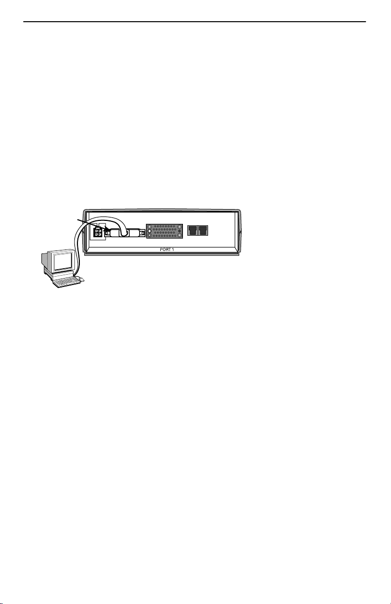
1. Create a DLCI for the data port.
Configuration
→
Data Ports
→
DLCI Records
2. Save the configuration.
3. Create a Management PVC using the data port DLCI just created.
Configuration
→
Management and Communication
→
Management PVC
Minimally, enter the following options:
– Name for the management PVC
– Interface IP Address and Subnet Mask, if different from the Node’s
– Primary Link for this Management PVC (the user data port)
– Primary DLCI (i.e., the data port DLCI)
4. Save the configuration.
Automatic Configuration
The FrameSaver unit provides several automatic configuration features. Frame Relay
Discovery and configuration is one of these features.
Main Menu
→
Auto-Configuration
The default discovery mode is 1MPort. In this mode, for each DLCI discovered on the
network, a multiplexed network DLCI and a standard data port DLCI will be configured
and connected, and a Management PVC will be embedded in the network DLCI.
NOTE:
When auto-configuration creates a multiplexed DLCI, but a standard DLCI is
needed, change the DLCI to Standard from the network DLCI Records screen:
Configuration
→
Network
→
DLCI Records
Other modes can be selected. See
Setting Up Automatic Configuration
in
Configuration
of the User’s Guide for information about other modes and how the Frame Relay
Discovery Mode can be changed.
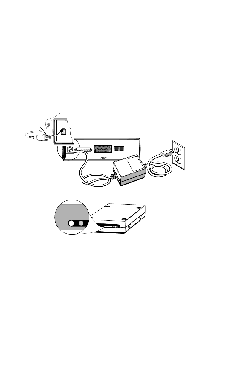
No automatic configuration occurs until the network cable is connected. If you do not
want management links configured or automatic configuration, change the default
setting for the Frame Relay Discovery feature.

9
Connecting to the Network
1. Insert the 8-pin connector of the RJ48C network cable into the network interface.
2. Insert the other end of the cable into the RJ48C modular jack.
POWER
COM
NET
DSX
99-16349
DTE
NOTE:
After connecting the network cable, wait a few minutes to allow
Auto-Configuration a chance to discover the frame relay characteristics
and DLCIs.
Verification Check:
Check the Network LEDs. Is the Sig (signal) LED on, and are the OOF (out of
frame), and ALM (alarm) LEDs off?
– If yes, the network interface is set up correctly and is ready to pass data.
– If no, check that both ends of the network cable are properly seated, then verify
that the network physical options are configured correctly.
Main Menu
→
Configuration
→
Network
→
Physical
Check Health and Status messages in the left column of the System and Test
Status screen to see the LMI status, to verify that LMI is up.
Main Menu
→
Status
→
System and Test Status
– If LMI Down, Network appears for more than three minutes, or any other
network-related status message appears, refer to the status information in
Operation and Maintenance
of the User’s Guide for possible reasons for the
messages and what can be done to resolve the problem.

10
Setting Up Service Provider Connectivity
at the Central Site
When management needs to be set up between a service provider’s customer and its
network operations center (NOC), a non-multiplexed DLCI must be configured to carry
management data between the customer’s central site and the NOC console. This
requires that a frame relay discovered DLCI needs to be modified. This is because all
auto-configured network DLCIs are configured as multiplexed DLCIs.
To set up NOC management:
1. Select DLCI Records on the network interface:
Configuration
→
Network
→
DLCI Records
2. Select Modify. The Modify DLCI Record for DLCI Number prompt appears.
3. Select the DLCI that will be used by pressing the spacebar until the correct DLCI
number appears, then select it.
4. Change the DLCI Type from Multiplexed to Standard.
The DLCI in connections. Update DLCI usage as follows: prompt
appears.
5. Select the Delete EDLCI Connections and Make a Mgmt Only PVC
option.
PVC connections for the selected DLCI are broken, the Port-1 DLCI mapped to
this network DLCI and the embedded management DLCI (EDLCI) are deleted, and
the selected DLCI will be reconfigured as a management PVC using the Node IP
Address.
Configuring SNMP Trap Managers and Trap Dial-Out
Once the FrameSaver unit is connected to the network, SNMP trap managers, SNMP
traps, and trap dial-out can be configured.
1. Select SNMP Traps.
Main Menu
→
Configuration
→
Management and Communication
→
SNMP Traps
2. Configure the following:
– Enable SNMP Traps.
– Identify the total Number of Trap Managers.
– Specify the IP address of the NMS(s) to which traps will be sent.
– Specify the network Destination for the Trap Manager(s).
– Select desired trap categories.
3. Save the configuration.
4. Return to the Main Menu.

11
Verifying the End-to-End Path
After installation of a remote site unit, run an IP Ping test to Ping the NMS at the central
site and verify that the entire path from the remote unit to the NMS is functioning. To run
the IP Ping test, NMS trap managers must have been configured for the remote unit.
One of those trap managers must be the central site NMS.
1. Select the IP Ping test.
Main Menu
→
Test
→
IP Ping
2. Enter the IP Address of the device being Pinged, then select Start.
NOTE:
When running tests, the cursor is positioned over the Start command. Press
Enter to start the test. Stop is displayed while the test is running. Press Enter
again to issue the Stop command.
– While the test is running, In Progress... is displayed in the Status field.
– When the test is finished, Alive. Latency =
nn
ms should appear as the
Status (
nn
being the amount of time the test took in milliseconds).
If any other message is displayed, additional testing will be required. See
Device
Messages
in
Operation and Maintenance
of the User’s Guide for information
about IP Ping-related messages.

12
Connecting to the DSX
1. Connect the 8-positon modular plug end of the DSX cable to the DSX-1 interface.
If your DSX cable has a DB15 end, use the DSX-1 adapter cable (see
Cables You
May Need to Order
on page 2).
Refer to the pin assignment information in the User’s Guide to ensure you have
proper connections.
2. Connect the other end of the cable to the CPE (customer premises equipment,
like a PBX).
3. Tighten the screws on each side of the connector to secure them.
POWER
COM
NET
DSX
99-16355
PBX
Verification Check:
Check the DSX LEDs. Is the Sig (DSX-1 signal) LED on, and are the DSX-1 OOF
(out of frame) and ALM (alarm) LEDs off?
– If so, the DSX interface is set up correctly and ready to communicate.
– If no, check that both ends of the DSX cable are properly seated and secured.
When OOF is on, match the Line Framing Format and Line Coding Format
options to the network provider’s settings.
When ALM is on, contact the service provider.
Check Health and Status messages in the left column of the System and Test
Status screen to verify that there are no DSX-1 Health and Status messages.
Main Menu
→
Status
→
System and Test Status
If any DSX-1 messages appear, refer to the status information in
Operation and
Maintenance
of the User’s Guide.
In the User’s Guide, see
Operation and Maintenance
for additional status information,
and
Troubleshooting
for additional troubleshooting information.

13
Connecting to the DTE
1. Connect one end of the DTE’s V.35 cable to the data port.
2. Plug the other end of the cable into the DTE.
3. Tighten the screws on each side of the connector to secure them.
POWER
COM
NET
DSX
99-16350
RJ48C
Jack
Verification Check:
Is the port OK LED on?
– If so, the port is ready to communicate.
– If not, check that both ends of the V.35 cable are properly seated and secured.
Then, check the DTE; RTS or DTR could be down on the DTE.
Check Health and Status messages in the left column of the System and Test
Status screen for messages.
Main Menu
→
Status
→
System and Test Status
– If System Operational appears, the Port-1 interface is set up correctly and
is operational.
– If System Operational does not appear, refer to the status information in
Operation and Maintenance
of the User’s Guide.
NOTE:
When any error conditions are detected, a status message will appear at the
bottom right corner of the screen.

14
Check PVC Connections
Check PVC connections to verify that all PVCs, including management PVCs, are
configured, and to see whether the PVC is active or not.
1. Press Esc to return to the Status menu.
2. Select PVC Connection Status.
The PVC Connection Status screen shows all PVC connections; the interface and
DLCI number of the source interface and DLCI number for the destination
interface. You can also see whether the PVC is active.
3. Verify that each PVC is active.
– If active, the FrameSaver unit should be passing data.
– If not active, no data traffic can be carried by the PVC. If the PVC is configured
correctly, the circuit may be down.
In the User’s Guide, see
Operation and Maintenance
for additional status information,
and
Troubleshooting
for additional troubleshooting information.
Check That Data is Being Received
1. Return to the Main Menu, then select Status.
2. Select Performance Statistics,and select an interface’s frame relay statistics
(e.g., Network Frame Relay).
Main Menu
→
Status
→
Performance Statistics
→
Network Frame Relay
3. Clear the statistics and see whether the counts for Frames Received and
Characters Received under the Frame Relay Link are incrementing, and verify that
there are no errors under the Frame Relay LMI statistics. Refresh the screen to
update the counts.
– If data is being received, the count increments after refreshing the screen.
– If data is not being received, recheck the cable connections, and replace or
repair a damaged cable. Recheck LMI status; you may need to contact your
service provider. Next, check the DLCI’s status.

15
!Important Safety Instructions
1. Read and follow all warning notices and instructions marked on the product or
included in the manual.
2. This product is intended to be used with a 3-wire grounding type plug – a plug
which has a grounding pin. This is a safety feature. Equipment grounding is vital to
ensure safe operation. Do not defeat the purpose of the grounding type plug by
modifying the plug or using an adapter.
Prior to installation, use an outlet tester or a voltmeter to check the ac receptacle
for the presence of earth ground. If the receptacle is not properly grounded, the
installation must not continue until a qualified electrician has corrected the
problem.
If a 3-wire grounding type power source is not available, consult a qualified
electrician to determine another method of grounding the equipment.
3. Slots and openings in the cabinet are provided for ventilation. To ensure reliable
operation of the product and to protect it from overheating, these slots and
openings must not be blocked or covered.
4. Do not allow anything to rest on the power cord and do not locate the product
where persons will walk on the power cord.
5. Do not attempt to service this product yourself, as opening or removing covers
may expose you to dangerous high voltage points or other risks. Refer all servicing
to qualified service personnel.
6. General purpose cables are provided with this product. Special cables, which may
be required by the regulatory inspection authority for the installation site, are the
responsibility of the customer.
7. When installed in the final configuration, the product must comply with the
applicable Safety Standards and regulatory requirements of the country in which it
is installed. If necessary, consult with the appropriate regulatory agencies and
inspection authorities to ensure compliance.
8. A rare phenomenon can create a voltage potential between the earth grounds of
two or more buildings. If products installed in separate buildings are
interconnected, the voltage potential may cause a hazardous condition. Consult a
qualified electrical consultant to determine whether or not this phenomenon exists
and, if necessary, implement corrective action prior to interconnecting the products.

16
9. In addition, if the equipment is to be used with telecommunications circuits, take
the following precautions:
— Never install telephone wiring during a lightning storm.
— Never install telephone jacks in wet locations unless the jack is specifically
designed for wet locations.
— Never touch uninsulated telephone wires or terminals unless the telephone
line has been disconnected at the network interface.
— Use caution when installing or modifying telephone lines.
— Avoid using a telephone (other than a cordless type) during an electrical
storm. There may be a remote risk of electric shock from lightning.
— Do not use the telephone to report a gas leak in the vicinity of the leak.
EMI Warnings
!WARNING:
This equipment has been tested and found to comply with the limits for a
Class A digital device, pursuant to Part 15 of the FCC rules. These limits are
designed to provide reasonable protection against harmful interference
when the equipment is operated in a commercial environment. This
equipment generates, uses, and can radiate radio frequency energy and, if
not installed and used in accordance with the instruction manual, may cause
harmful interference to radio communications. Operation of this equipment
in a residential area is likely to cause harmful interference, in which case, the
user will be required to correct the interference at his own expense.
The authority to operate this equipment is conditioned by the requirements
that no modifications will be made to the equipment unless the changes or
modifications are expressly approved by Paradyne.
In order to maintain compliance with FCC limits, any supplied ferrite chokes
must be installed in accordance with the card installation instructions.
!WARNING:
To Users of Digital Apparatus in Canada:
This Class A digital apparatus meets all requirements of the Canadian
interference-causing equipment regulations.
Cet appareil numérique de la classe A respecte toutes les exigences du
règlement sur le matériel brouilleur du Canada.

17
Government Requirements
Certain governments require that instructions pertaining to connection to the telephone
network be included in the user documentation. Specific instructions are listed in the
following sections.
United States
Notice to Users of the Telephone Network
This equipment complies with Part 68 of the FCC rules. On the bottom of the housing is
a label that contains, among other information, the FCC registration number for this
equipment. If the unit comes with an integral modem, the ringer equivalence number
(REN) will also be labeled. If requested, please provide this information to your
telephone company.
The REN is used to determine the number of devices that may be connected to the
telephone line. Excessive RENs on the line may result in the devices not ringing in
response to an incoming call. In most, but not all areas, the sum of RENs should not
exceed five (5.0). To be certain of the number of devices that can be connected to the
line, as determined by the total RENs, contact the local telephone company.
If your unit causes harm to the telephone network, the telephone company may
discontinue your service temporarily. If possible, they will notify you in advance. But if
advance notice is not practical, you will be notified as soon as possible. You will be
advised of your right to file a complaint with the FCC.
Your telephone company may make changes in facilities, equipment, operations, or
procedures that could affect the proper operation of your equipment. If so, you will be
given advance notice so as to give you an opportunity to maintain uninterrupted
service.
No repairs may be performed by the user. Should you experience difficulty with this
equipment, refer to the
Warranty, Sales, Service, and Training Information
on page 19.
Make the T1 network connection using a Universal Service Order Code (USOC) type
RJ48C jack for single-line installations and type RJ48H jack for multiline installations.
Specify both the Service Order Code 6.0F, as well as the proper Facility Interface
Code, to the telephone company when ordering the T1 line. The T1 equipment can be
configured to support any of the framing format and line signaling techniques shown in
the table below. The T1 equipment’s configuration must correspond to the T1 line’s
parameters.
T1 Facility Interface Codes
Interface Code Description
04DU9-BN 1.544 Mbps superframe format (SF) without line power
04DU9-DN 1.544 Mbps SF and B8ZS without line power
04DU9-1KN 1.544 Mbps ANSI ESF without line power
04DU-1SN 1.544 Mbps ANSI ESF and B8ZS without line power

18
After the telephone company has installed the requested services and jacks, you can
connect the unit with the cable provided. An FCC-compliant telephone cord and
modular plug are provided with this equipment. This equipment is designed to be
connected to the telephone network or premises wiring using a compatible modular
jack that is Part 68 compliant.
Canada
Notice to Users of the Canadian Telephone Network
The Industry Canada label identifies certified equipment. This certification means that
the equipment meets telecommunications network protective, operational and safety
requirements as prescribed in the appropriate Terminal Equipment Technical
Requirements document(s). The Department does not guarantee the equipment will
operate to the user’s satisfaction.
Before installing this equipment, users should ensure that it is permissible to be
connected to the facilities of the local telecommunications company. The equipment
must also be installed using an acceptable method of connection. The customer should
be aware that compliance with the above conditions may not prevent degradation of
service in some situations.
Repairs to certified equipment should be coordinated by a representative designated by
the supplier. Any repairs or alterations made by the user to this equipment, or
equipment malfunctions, may give the telecommunications company cause to request
to disconnect the equipment.
Users should ensure for their own protection that the electrical ground connections of
the power utility, telephone lines and internal metallic water pipe system, if present, are
connected together. This precaution may be particularly important in rural areas.
CAUTION:
Users should not attempt to make such connections themselves, but should
contact the appropriate electric inspection authority, or electrician, as
appropriate.
The Ringer Equivalence Number (REN) assigned to each terminal device provides an
indication of the maximum number of terminals allowed to be connected to a telephone
interface. The termination on an interface may consist of any combination of devices
subject only to the requirement that the sum of the Ringer Equivalence Numbers of all
the devices does not exceed 5.
If your equipment is in need of repair, refer to
Warranty, Sales, Service, and Training
Information
on page 19.

19
Warranty, Sales, Service, and Training Information
Contact your local sales representative, service representative, or distributor directly for
any help needed. For additional information concerning warranty, sales, service, repair,
installation, documentation, training, distributor locations, or Paradyne worldwide office
locations, use one of the following methods:
Internet: Visit the Paradyne World Wide Web site at www.paradyne.com.
(Be sure to register your warranty at www.paradyne.com/warranty.)
Telephone: Call our automated system to receive current information by fax or to
speak with a company representative.
— Within the U.S.A., call 1-800-870-2221
— Outside the U.S.A., call 1-727-530-2340
Document Feedback
We welcome your comments and suggestions about this document. Please mail them
to Technical Publications, Paradyne Corporation, 8545 126th Ave. N., Largo, FL 33773,
document in your correspondence. Please include your name and phone number if you
are willing to provide additional clarification.
Trademarks
FrameSaver is a registered trademark of Paradyne Corporation. All other products and
services mentioned herein are the trademarks, service marks, registered trademarks or
registered service marks of their respective owners.
Patent Notification
FrameSaver products are protected by U.S. Patents: 5,550,700 and 5,654,966. Other
U.S. patents pending.
Copyright 1999 Paradyne Corporation
Other manuals for FrameSaver SLV 9124
2
Table of contents
Other Paradyne Measuring Instrument manuals