Paragon Pro Panellift Hangpro 150 User manual

O
O
O
O
P
P
E
E
R
R
A
A
T
T
O
O
R
R
’
’
S
S
M
M
A
A
N
N
U
U
A
A
L
L
Model 150
WARNING
© 2018 Paragon Pro Manufacturing Solutions All Rights Reserved
Read and become familiar with this manual BEFORE operating unit.
Before operating this equipment, thoroughly read this set of instructions, make sure
you understand them, and only then follow the step-by-step directions. Failure to do
so could result in serious property damage and / or serious bodily injury.

To our valued customer,
Thank you for choosing a product by
Manufacturing Solutions. We are pleased that we are able to provide equipment to
make your work easier.
Our efforts are focused on producing the finest quality equipment of which we
are capable. We make sure to spend extra time and effort on our design and produc-
tion in order to reduce your time and effort spent using the product.
We take pride in providing the best for our customers. Quality, innovation, and
excellence are all qualities this company ensures. No product is sent without being
factory tested and inspected to ensure the highest quality for you.
It all began in 1972 when Roland Young designed our first product, the PANEL-
LIFT® Brand Drywall Lift, and revolutionized the drywall industry. To this day we are
continuously making advancments in manufacturing and design.
Thank you again for giving us the opportunity to work with you. Any questions
or comments that you have are always welcome.
Thank you for choosing a product by
Manufacturing Solutions. We are pleased that we are able to provide equipment to

CONTENTS
Warning / Instructional Information . . . . . . . . . . . . . . . . . . . . . . . . . . . . . . . . . . Page 1
Cable Inspections/Replacement . . . . . . . . . . . . . . . . . . . . . . . . . . . . . . . . . . . . . . Page 2
Care and Maintenance . . . . . . . . . . . . . . . . . . . . . . . . . . . . . . . . . . . . . . . . . . . . . . Page 3
Components . . . . . . . . . . . . . . . . . . . . . . . . . . . . . . . . . . . . . . . . . . . . . . . . . . . . . . . Page 4
Tools . . . . . . . . . . . . . . . . . . . . . . . . . . . . . . . . . . . . . . . . . . . . . . . . . . . . . . . . . . . . . . Page 4
Assembly . . . . . . . . . . . . . . . . . . . . . . . . . . . . . . . . . . . . . . . . . . . . . . . . . . . . . . . . Pages 5 - 7
Operation . . . . . . . . . . . . . . . . . . . . . . . . . . . . . . . . . . . . . . . . . . . . . . . . . . . . . . . Pages 8 - 9
Parts Index . . . . . . . . . . . . . . . . . . . . . . . . . . . . . . . . . . . . . . . . . . . . . . . . . . . . . . . Page 10
Safety Information . . . . . . . . . . . . . . . . . . . . . . . . . . . . . . . . . . . . . . . . . . . . . . . . Page 11
Warranty . . . . . . . . . . . . . . . . . . . . . . . . . . . . . . . . . . . . . . . . . . . . . . . . . . . . . . . . Page 12
ALL PHOTOS ARE FOR ILLUSTRATIVE PURPOSES ONLY.
ALWAYS WEAR PROPER PERSONAL PROTECTIVE EQUIPMENT.

1
WARNING
Read and follow these warnings and the instructions that follow. Failure to do so could result in serious
property damage and/or serious bodily injury.
Decal Warnings:
Please note these warning decals
located on the HANGPRO™. These
decals do not replace the necessity of
reading and understanding the
instrucons within this operators
manual.
Cau�on When Assembling your HangPro™
Align the Upper Mast Assembly with the Lower Mast
Assembly so the two bolt holes line up. THIS IS A PINCH
POINT. KEEP HANDS AWAY FROM THE JOINT WHERE THE
UPPER AND LOWER MASTS MEET.
Pinch Point
Cau�on When Assembling your HangPro™
Insert BOTH 3’ x 3/8” bolts and 3/8” Nylock nuts. FAILURE
TO INSERT BOTH BOLTS COULD RESULT IN THE UPPER
MAST PIVOTING RAPIDLY DOWNWARD, POTENTIALLY
CAUSING PROPERTY DAMAGE OR SERIOUS INJURY.
IN A DRY ENVIRONMENT AVOID MOISTUREAND WATER

2
ASME Standards for wire rope (cable) inspection and replacement
Reprinted with permission from ASME B30.19 Cableways
The following is intended as a helpful guide to the general topic of inspection and replacement
of wire rope (cable). It is not intended to be an exhaustive treatment of the topic.
Frequent inspection (at least daily) by a competent person and prompt replacement of any cable that shows any sign of
wear is the responsibility of the owner and the operator of the PANELLIFT®Drywall Lift.
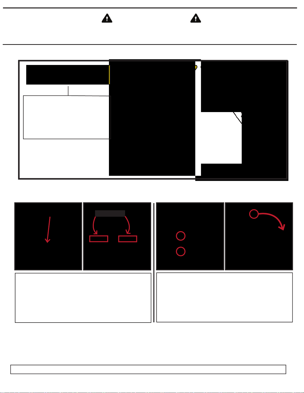
With reference to the chart below at 19-2.4.3(b)(6) the Panellift® Drywall Lift cable is a nominal 1/8” high tensile cable (rope).
(3) Care shall be taken when inspecting sectionsofrapid deterioration,
such as the following:
(a)sections in contactwith saddles,equalizersheaves, or othersheaves,
including track cable sheaves, where rope travel is limited;
(b) sections of the rope at or near terminal endswhere corroded or broken
wiresmaydevelop.
19-2.4.3 Rope Replacement
(a) No precise rules can be given for determination of the exact time for
rope replacement, since many variable factorsare involved. Once a rope
reachesanyone of the specified removal criteria,itmaybe allowed to
operate to the end of the work shift, based on the judgment of a qualified
person. The rope shall be replaced after thatwork shift, at the end of the day,
or at the latest time prior to the equipmentbeing used by the next work shift.
(b) Removal criteria for rope replacement shall be as follows:
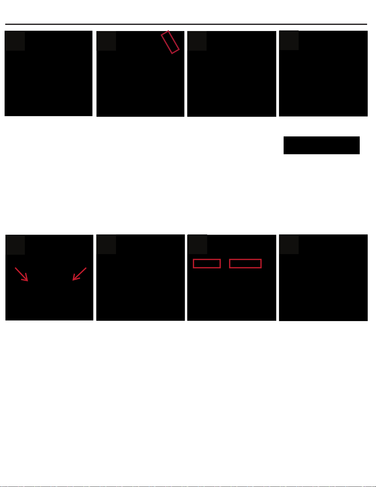
(1) In running ropes, six randomlydistributed broken wiresin one lay,
or three broken wiresin one strand in one lay.
(2) One outer wire,broken at the contact pointwith the core of the rope,
thathasworked its wayout of the rope structure and protrudesand loopsout
from the rope structure. Additional inspection of this section is required.
(3) Wear of one-third the original diameter of outside individual wires.
(4) Kinking, crushing,birdcaging,or any other damage resulting in
distortion of the rope structure.
(5)Evidence of heatdamage fromanycause.
(6) Reductions from nominal diameter greater than those shown below:
(7) In standing ropes, more than two broken wires in one lay in sections
beyond end connections, or more than one broken wire at an end connection.
(c) Brokenwireremovalcriteriacited in this Volumeapply to wirerope
operating on steel sheaves and drums. The user shall contact the sheave,
drum,or cablewaymanufacturer, or aqualified person for broken wire
removal criteria for wire ropesoperating on sheaves and drumsmade of
material other than steel.
(d) Replacementrope shall haveanominal strength rating at leastequal
to the original rope furnished or recommended by the cablewaymanufacturer
or designer, or a qualifiedperson. Any deviation from the originalsize,grade,
or construction shall be specified by the rope manufacturer, the cableway
manufacturer or designer, or aqualified person.
(e) RopesNotin Regular Use. All rope thathasbeen idle for aperiod
of a month or more due to shutdown or storage of a cablewayon which
it is installed shall be given an inspection in accordance with para.19-
2.4.2(b) before it is placed in service. Thisinspection shall be for all types of
deteriorationandshall be performed by an appointed or authorizedperson.
(f) Inspection Records
(1) Frequentinspection-no recordsrequired.
(2) Periodicinspection -in order to establish data as a basis for judging
the proper time for replacement, adated reportofrope condition at each
periodicinspection shall be kepton file. Thisreport shall cover points of
deterioration listed in para.19-2.4.2(b)(2).
(g) A long-range inspection program should be established and should include
records on examination of rope removed from service so a relationship can
be established between visual observation and actual condition of the internal
structure.
(00) General
…The use of cableways, cranes, derricks, hoists, hooks, jacks, and slings
is subject to certainhazards thatcannot be met by mechanicalmeansbut
only by the exercise of intelligence, care,and common sense. It is therefore
essential to have personnel involved in the use and operation of equipment
who are competent, careful,physicallyand mentallyqualified,and trained in
the safe operation of the equipmentand the handling of the loads. Serious
hazardsareoverloading,dropping or slipping of the loadcaused by improper
hitching or slinging,obstructing the free passage of the load,and using
equipment for apurpose for which it wasnotintended or designed.
…
Section 19-2.4: Rope Inspection,Replacement, and Maintenance
19-2.4.1 General. Sheave diameters, drum diameters, and rope design
factorsare limited because of cablewaydesign configuration.Due to
these parameters, inspection in accordance with para.19-2.4.2 to detect
deterioration and timely replacementin accordance with para.19-2.4.3 are
essential.
19-2.4.2 Inspection
(a) Frequent Inspection
(1) All running ropes in service should be visually inspected once each
working day. A visual inspection shall consist of observation of all rope that
can reasonablybe expected to be in use during the day’s operations. These
visual observations should be concerned with discovering gross damage that
may be an immediate hazard,such as listed below:
(a) distortion of the rope such as kinking, crushing,unstranding,birdcaging,
main stranddisplacement, or coreprotrusion.Loss of ropediameter in a short
rope length or unevenness of outer strands should provide evidence that the
rope or ropesare to be replaced.
(b) general corrosion;
(c) broken or cut strands;
(d) number, distribution,and type of visible broken wires[see paras. 19-
2.4.3(b)(1),(2),and (7) for further guidance];
(e) core failure in rotation-resistantropes;when damage is suspected, the
rope shall either be removed from service or given an inspection as detailed
in para.19-2.4.2(b).
(2) Care shall be taken when inspecting sectionsofrapid deterioration,
such as flange points, crossover points, and repetitive pickup points on
drums.
(3) Care shall be taken when inspecting certain ropes, such as
rotation-resistantropes,because of their higher susceptibility to damage
and increased deterioration when working on equipmentwith limited design
parameters. The internal deterioration of rotation-resistantropesmaynot be
readilyobservable.
(b) Periodic Inspection
(1) The inspection frequency shall be determined by a qualified person
and shall be based on such factors as expected rope life (determined by
experience on the particular installation or similar installations), severity of
environment, percentage of capacity lifts, frequency rates of operation,and
exposure to shockloads. Inspections need notbe at equal calendar intervals
and should be more frequent as the rope approaches the end of its useful life.
The inspection shall be made at least every1000 hr of cablewayoperation or
annually, whichever comes first.
(2) Periodicinspections shall be performed by an appointed or
authorizedperson. Thisinspectionshallcover the entirelength of rope. Only
the surface wires of the rope need be inspected.No attempt should be made
to open the rope. Any deterioration resulting in appreciable loss of original
strength, such as described below, shall be noted,and adetermination shall
be made as to whether furtheruse of the ropewouldconstitute a hazard:
(a) points listed in para.19-2.4.2(a):
(b) reduction of rope diameter below nominal diameter due to loss of core
support, corrosion,or wear of outside wires;
(c) severely corroded or broken wiresatend connections;
(d) severely corroded, cracked, bent, worn, or improperly applied end
connections.
Max. Allowable
Reduction From
Rope Diam. Nominal Diam.
Up to 5/16 in. (8 mm) 1/64 in. (0.4 mm)
Over 3/8 in. up to 1/2 in. (13 mm) 1/32 in. (0.8 mm)
Over 9/16 in. up to 3/4 in. (19 mm) 3/64 in. (1.2 mm)
Over 7/8 in. up to 1 1/8 in. (29 mm) 1/16 in. (1.6 mm)
Over 1 1/4 in. up to 1 1/2’ in. (38 mm) 3/32 in. (2.4 mm)

3
CARE AND MAINTENANCE
Inspect cable FREQUENTLY.
(At least daily and before each use) Replace at the first
sign of wear.
Occasionally oil the cable sheaves and caster bearings.
in a dry place.
Apply household paraffin to the surfaces of the telescoping
sections, for smoother action.
Takereasonable care to avoiddamaging the
DrywallLift when transporting it.
Do nothammer on any members or components of the
DrywallLift.
Store the HANGPRO™ Drywall Lift
HANGPRO™
HANGPRO™

COMPONENTS
A: Square Cradle
B: Upper Mast
C: Wheel Leg
D: Lower Mast
E: Winch
F: Cable
G: Cable Keeper
4
• ADJUSTABLE WRENCH • 3/8” WRENCH
• 9/16” WRENCH
• 7/16 WRENCH
• 5/8” WRENCH
• FLATHEAD SCREWDRIVER
TOOLS REQUIRED
A: Square Cradle
ABCD
EFG

5
1. Place the Lower Mast Assembly face down on the floor as shown.
2. Attach the Wheel Leg Assembly to the Lower Mast Assembly with the
warning decal facing the top of the mast section. Insert the tapered tabs into the slots as
shown.
3. Secure the Wheel Leg Assembly to the Lower Mast Assembly with two 3” x 3/8” Bolts
and 3/8” Nylock nuts. Tighten with two 9/16” wrenches, or adjustable wrench.
4. Stand the assembled Lower Mast and Wheel Leg upright.
5. Align the channels on the back of the Square Cradle to the guide plates on the Lower Mast
as shown, with the support hooks at the bottom and facing away from you. Carefully lower
the Square Cradle to the floor.
6. Align the Upper Mast Assembly with the Lower Mast Assembly so the two bolt holes line
up.
6a. This is a PINCH POINT. KEEP HANDS AWAY FROM THE JOINT WHERE THE UPPER
AND LOWER MASTS MEET.
7. Insert both 3” x 3/8” bolts and Nylock nuts. FAILURE TO INSERT BOTH BOLTS COULD
RESULT IN THE UPPER MAST PIVOTING RAPIDLY DOWNWARD, POTENTIALLY
CAUSING PROPERTY DAMAGE OR SERIOUS INJURY.
ASSEMBLY
1 2 34
5 6 6a 7

6
8. Place the winch on the mounting plate at the back of the HANGPRO™, with the gear side
of the winch near the mast.
9. Insert three 7/8” x 3/8” bolts down through the winch base and mounting plate and attach
the 3/8” Nylock nuts from beneath. Tighten with two 9/16” wrenches or adjustable wrench.
10. Attach the Winch Handle by pushing in and turning clockwise.
11. Secure the handle with the bolt, washer, spacer and spring provided with the winch as
shown.Also noted in the accompanying Winch Manual. Tighten with a 3/8” wrench.
11a. It may be necessary to place a flathead screwdriver into the winch gears to prevent
them from turning as you tighten the winch handle and winch handle bolt.
12. Unwrap the cable and string the loose end over the sheave at the top of the Mast. If the
Cable Keeper is in place you may need to remove it by loosening the nut visible in fig.15
and 16. DO NOT REMOVE THE BOLT.
13. Run the cable over the Cable Roller and down through the opening in the upper handle
as shown in the Image above.
14. From inside the winch spool, thread the loop anchor of the cable through the round hole
in the sidewall of the spool. Secure the loop with the carriage bolt, washer and nut
provided.
ASSEMBLY CONTINUED
8910 11
11a 12 13 14

ASSEMBLY CONTINUED
7
8. Place the winch on the mounting plate at the back of the HANGPRO™, with the gear side
of the winch near the mast.
9. Insert three 7/8” x 3/8” bolts down through the winch base and mounting plate and attach
the 3/8” Nylock nuts from beneath. Tighten with two 9/16” wrenches or adjustable wrench.
10. Attach the Winch Handle by pushing in and turning clockwise.
11. Secure the handle with the bolt, washer, spacer and spring provided with the winch as
shown.Also noted in the accompanying Winch Manual. Tighten with a 3/8” wrench.
11a. It may be necessary to place a flathead screwdriver into the winch gears to prevent
them from turning as you tighten the winch handle and winch handle bolt.
12. Unwrap the cable and string the loose end over the sheave at the top of the Mast. If the
Cable Keeper is in place you may need to remove it by loosening the nut visible in fig.15
and 16. DO NOT REMOVE THE BOLT.
13. Run the cable over the Cable Roller and down through the opening in the upper handle
as shown in the Image above.
14. From inside the winch spool, thread the loop anchor of the cable through the round hole
in the sidewall of the spool. Secure the loop with the carriage bolt, washer and nut
provided.
17a:
17b:
14a. The carriage bolt head must be positioned through a square hole on the inside of the
winch spool with the washer and nut on the outside of the spool wall. Tighten with 3/8”
wrench.
15. Attach the Cable Keeper to the top of the Upper Mast.
16. Tighten the Cable Keeper with a 5/8 wrench and an adjustable wrench so the nut is firmly
secured to the bolt. DO NOT OVERTIGHTEN! THE SHEAVE MUST BE ABLE TO TURN
FREELY.
14a 15 16
17a
17b

OPERATION
PREPARING DRYWALL PANELS
Drywall panels are typically stocked leaning horizontally in small stacks
against walls. When the drywall bundle is opened the first panel has to be
flipped around so the good side of the panel is facing out.
LOADING A PANEL
Center the lift on the panel and position about an inch away from the
panel. Lower the cradle to the floor. Lift one end of the panel onto the
cradle support hooks. Lean the panel back against the cradle frame.
TRANSPORTING
Turn the winch handle clockwise to raise the panel about 12 inches off the
floor, with one hand holding the vertical handle and the other hand gripping
the top edge of the panel, lean the lift back slightly onto the rear wheels and
push like a hand truck. Lean the lift forward onto the front wheels to trans-
port the loaded lift sideways through doorways and hallways.
POSITIONING
Position the lift so the casters are 8 to 12 inches away from the wall.
While standing at the back of the lift, carefully lean the lift and panel
forward onto the front wheels and againsts the wall. The lift will not
kick away from the wall because the wheels do not pivot.
LIFTING AND HOLDING
With a firm grip on the horizontal handle, turn the winch
handle clockwise to raise the panel. The winch auto
locks and the panel will be held securely against the wall.
CAUTION: DO NOT RAISE THE PANEL OVER 24
INCHES UNLESS THE LIFT IS STANDING ON THE
FRONT WHEELSAND THE PANEL IS LEANING
AGAINST THE WALL.
8

USING THE FRONT WHEELS FOR PRECISE POSITIONING
When the lift is leaned forward onto the front wheels it can be
moved side-to-side for the precise positioning before or after
lifting the panel.
REMOVING THE LIFT AFTER PANEL IS SECURED
Secure the panel to the wall. Turn the winch handle counter
clockwise to lower the cradle before moving the lift.
OPERATION CONTINUED
LIFTING AND HOLDING
With a firm grip on the horizontal handle, turn the winch
handle clockwise to raise the panel. The winch auto
locks and the panel will be held securely against the wall.
CAUTION: DO NOT RAISE THE PANEL OVER 24
INCHES UNLESS THE LIFT IS STANDING ON THE
FRONT WHEELSAND THE PANEL IS LEANING
AGAINST THE WALL.
9
TRANSPORTING THROUGH A DOORWAY OR HALLWAY
Load a panel as described on prior page. Turn the winch handle clockwise
to raise the panel 6 to 12 inches off the floor. With one hand on the vertical
handle and the other gripping the top edge of the panel, lean the lift and
panel forward onto the front wheels. Position the lift so the end of the panel
is pointing toward the doorway or hallway. Push the lift sideways on the
front wheels.

10
PARTS INDEX

SAFETY INFORMATION
11
Chemical Hazard CAS# % By Weight
Arsenic
Cadmium
Chromium
Ethylbenzene
Lead
Methanol
Methylene Chloride (Dichloromethane)
Nickel
Propylene glycol monobutyl ether
Toluene
Carbon Black
Cancer
Developmental
Cancer, Developmental
Cancer
Cancer
Developmental
Cancer
Cancer
Cancer
Developmental
Cancer
7440-38-2
7440-43-9
7440-47-3
100-41-4
7439-92-1
67-56-1
75-09-2
7440-02-0
5131-66-8
108-88-3
1333-86-4
Trace
Trace
Trace
Trace
Trace
Trace
Trace
Trace
Trace
Trace
Trace

WARRANTY
12
PARAGON PRO MANUFACTURING SOLUTIONS INC
LIMITED WARRANTY
TELPRO INC products manufactured by PARAGON PRO MANUFACTURING SOLUTIONS INC are warranted to be
free from defects in material and workmanship under normal use for one year from date of purchase.
If a TELPRO INC product is proven to be defective in material or workmanship within the covered time frame
from the date of purchase, return the defective part to PARAGON PRO MANUFACTURING SOLUTIONS INC and
we will either repair or replace the part at our option. We will neither assume nor authorize any other person
to assume for us any other liability.
Written notice including commercial invoice detailing the nature of the defect, date of purchase, and the
company from which you purchased your unit must be received and acknowledged by PARAGON PRO MANU-
FACTURING SOLUTIONS INC before any units may be returned. Shipping costs shall be the responsibility of the
product purchaser.
This warranty shall not apply to any equipment that has been repaired or altered outside of the factory in any
way so as in our judgment to aect its stability or reliability nor which has been subjected to abuse, misuse, or
negligence.
PARAGON PRO MANUFACTURING SOLUTIONS INC reserves the right to make changes or improvements in
design without incurring obligation to install the same on previous units.
PARAGON PRO MANUFACTURING SOLUTIONS INC shall not be liable for loss, damage, or expense directly or
indirectly from use of its products, their transportation, their repair, or from any other cause. Acceptance of
the manufacturer’s product constitutes agreement to the terms of this warranty and further that the manufac-
turer shall have no liability for any special or consequential damages.
This Warranty is in lieu of all warranties express or implied.
Fill in the following information, attach a copy of your sales receipt or invoice and le in a safe place.
Date of purchase: __________/__________/___________
Name& model# _______________________________________________________________________
Serial #: __________________________________________
NOTE: The following components of the PANELLIFT® Model 439 Drywall Lift are warranted to be free from
defects in material and workmanship under normal use for three years from date of purchase.
Part# Description
52-03 #35 chain assembly 52-05 #40 chain assembly
52-07 #50 chain assembly 52-09 1 1/4” #50 roller assembly
52-10 #Outer planet set w/ bronze 52-11 Drive assembly
52-11 #1/2” x 2 1/4”Shoulder bolt w/ fastners 52-15 Clutch assembly w/sprocket
52-16 #40 Winch drive chain

Questionsabout assembly?
Can’t find a part?
Need some other help?
Call us:
1.800.448.0822
701.775.0551
We’ll get you set up!
W
W
W
e
W
W
e
WeW
’ll get
’ll get
’ll get
’ll get
’ll get
’ll get
’ll get
’ll get
’ll get
’ll get
’ll get
’ll get
’ll get
’ll get
’ll get
y
ou set up!
y
y
y
ou set up!
ou set up!
ou set up!
ou set up!
ou set up!
ou set up!
ou set up!
ou set up!
ou set up!
ou set up!
ou set up!
ou set up!
ou set up!
ou set up!
ou set up!
ou set up!
ou set up!
ou set up!
ou set up!
ou set up!
ou set up!
ou set up!
ou set up!
ou set up!
ou set up!
ou set up!
ou set up!
W
W
W
W
W
W
W
e
W
e
WeW
W
e
W
e
WeW
W
W
’ll get
’ll get
’ll get
’ll get
’ll get
’ll get
’ll get
’ll get
’ll get
’ll get
’ll get
’ll get
’ll get
’ll get
’ll get
’ll get
’ll get
’ll get
’ll get
’ll get
’ll get
’ll get
’ll get
’ll get
’ll get
’ll get
y
ou set up!
y
y
y
ou set up!
y
y
ou set up!
ou set up!
ou set up!
ou set up!
ou set up!
ou set up!
ou set up!
ou set up!
ou set up!
ou set up!
ou set up!
ou set up!
ou set up!
ou set up!
ou set up!
ou set up!
ou set up!
ou set up!
ou set up!
ou set up!
ou set up!
ou set up!
ou set up!
ou set up!
ou set up!
ou set up!
ou set up!
ou set up!
ou set up!
ou set up!
ou set up!
ou set up!
ou set up!
ou set up!
ou set up!
ou set up!
ou set up!
ou set up!
ou set up!
ou set up!
ou set up!
ou set up!
ou set up!
ou set up!
ou set up!
ou set up!
ou set up!
Table of contents
Other Paragon Pro Lifting System manuals

Paragon Pro
Paragon Pro Telpro PanelLift 460 User manual

Paragon Pro
Paragon Pro CABINETIZER 72 User manual

Paragon Pro
Paragon Pro Telpro 294 Quick setup guide

Paragon Pro
Paragon Pro PANELIFT 439 User manual

Paragon Pro
Paragon Pro Doorminator 3070 User manual

Paragon Pro
Paragon Pro PANEL LIFT 117 User manual

Paragon Pro
Paragon Pro Telpro The Troll 112 User manual
Popular Lifting System manuals by other brands

UltraLift
UltraLift Ultralift Phoenix Wiring diagram

Bend-Pak
Bend-Pak HDS-40X Service manual

Bend-Pak
Bend-Pak HD-14T Installation and operation manual

Bend-Pak
Bend-Pak 5175153 Installation and operation manual

PRO LIFTS
PRO LIFTS VMB TL-075 Operating instructions & user manual

Hillrom
Hillrom Liko Ultra Series Instructions for use