Parallax Lab PE Platform Manual

599 Menlo Drive, Suite 100
Rocklin, California 95765, USA
Office: (916) 624-8333
Fax: (916) 624-8003
Sales:sales@parallax.com
Technical: [email protected]
Web Site: www.parallax.com
Copyright © Parallax Inc. ●PE Platform Setup v1.0 ●11/2/2006 ●Page 1 of 12
PE Platform Setup
PROPELLER EDUCATION KIT LAB SERIES
Introduction
The Propeller Education (PE) Kit Platform and Propeller Plug USB to serial converter/programming
tool are shown in Figure 1. The PE Platform is an array of breadboards with a PropellerTM
microcontroller in the center along with support circuits that make it a convenient and reusable
project platform. The support circuits include:
•5.0 V and 3.3 V voltage regulators
•EEPROM for non-volatile program storage
•5 MHz external crystal oscillator for precise clock signal
•Reset button for manual program restarts
•LED power indicator
•9 V battery-to-breadboard connector
•4-pin Propeller Plug header for program downloads and bidirectional communication with the
PC.
In this lab, you will assemble the PE Platform and run a test program to verify that the platform is
correctly wired and fully functional. If there is a wiring error, you will also perform the trouble-
shooting steps necessary to find and correct the error.
Figure 1: PE Kit Platform

Copyright © Parallax Inc. ●PE Platform Setup v1.0 ●11/2/2006 ●Page 2 of 12
Prerequisites
These labs assume prior microcontroller experience. Although this first lab provides wiring
diagrams, future labs will not. As a minimum, you should have experience building circuits from
schematics as well as experience with some form of computer or microcontroller programming
language.
L
Resources for Beginners: For introductions to building circuits, microcontroller programming, and much more
“prior microcontroller experience”, try either the BASIC Stamp Activity Kit or BASIC Stamp Discovery kit. Both
kits have everything you’ll need to get started, including a BASIC Stamp 2 microcontroller, project board, the
introductory level What’s a Microcontroller? text and parts for every activity. The What’s a Microcontroller?
text is also available for free PDF download from www.parallax.com, and both kits are available for purchase
from the web site as well as from a variety of electronics retailers and distributors. To find a retailer or
distributor near you, check the Distributors list under the Company category at the Parallax web site.
Procedure Overview
The goal of this lab is to prepare the PE Platform for use with future labs by following these steps:
•Taking an inventory of equipment and parts
•Installing the Propeller Tool (v1.0 or newer) software
•Assembling the PE Platform
•Testing power and programming connections
•Testing the crystal oscillator and the programming connections to EEPROM.
•Testing I/O pins as both inputs and outputs
•Troubleshooting if necessary
Since the PE Platform will be the microcontroller system at the heart of the forthcoming lessons and
labs, all its circuits should be tested. This will help rule out potential wiring errors, which can easily
slip by unnoticed as you build the PE Platform circuits.
Equipment and Parts
You will need the following to complete this lab:
•Computer with Microsoft Windows 2000 or XP, and an available USB port
•PE Platform Parts listed in Table 1
The following equipment is optional, but extremely useful:
•Needle-nose pliers and wire cutter/stripper
•Voltmeter
•Digital storage oscilloscope
•Antistatic mat and bracelet
! ESD Precautions : Electrostatic discharge (ESD) can damage the integrated circuits (ICs) in this kit. If you
have an antistatic bracelet and mat, use them. If you don’t, handling the gray bag and black foam before
handling the ICs will greatly reduce the possibility of a static zap that could damage the components. Another
strategy to reduce the risk is to handle ICs by their black plastic cases and avoid touching their metal pins.

Copyright © Parallax Inc. ●Application Note Title and Version ●11/2/2006 ●Page 3 of 12
Table 1: Parts List – PE Platform
Part Number Quantity Description
130-32305 1 Propeller DIP Plus Kit (See Table 2 for this kit’s parts list.)
32201 1 Propeller Plug USB/Serial converter + USB cable
700-00077 3 Breadboards, Prototyping (30 rows x 12 columns)
700-00081 4 Breadboards, Power Rail (26 rows x 2 columns)
Table 2: Parts List - Propeller DIP Plus Kit (130-32305)
(Parts and quantities subject to change without notice)
Part Number Quantity Description
571-32305 1 9 V battery clip
201-01085 2 Capacitor, Electrolytic, 6.3 V, 1000 µF
201-04740 1 Capacitor, Electrolytic, 25 V, 0.47 µF
150-01011 1 Resistor, CF, 5%, 1/4 watt, 100 Ω
150-01030 1 Resistor, CF, 5%, 1/4 watt, 10 kΩ
251-05000 1 Crystal 5.000 MHz, 20 pF, HC-49/µs
350-00001 1 LED Green T1 3/4
400-00002 1 Pushbutton - normally open
451-00302 1 2-pin m/m header
451-00406 1 Extended right angle m/m 4 pin header with 0.1 spacing
601-00513 1 3.3 V regulator, TO92 package
601-00506 1 5.0 V regulator, TO92 package
602-00032 1 32 kB EEPROM, DIP-8
800-00016 6 Bags of 10 Jumper Wires
P8X32A-D40 1 Propeller Chip P8X32A - 40 pin DIP
120-00003 1 Propeller DIP pin map sticker
3Take an inventory of the components in the Propeller DIP Plus Kit. If anything is missing,
replacement parts can be obtained from www.parallax.com using the part numbers shown.
Software and Driver Installation
The Propeller Tool software is available for download from the Parallax web site. One of its default
installation features is the USB drivers for the Propeller Plug communication and programming tool.
When you install the software, it will also install the USB drivers your PC will need to communicate
with the Propeller Plug by default.
3Download Setup-Propeller-Propeller-Tool-v1.0.exe (or newer) from www.parallax.com.
3Run the setup program to install the Propeller Tool software and FTDI USB drivers for PC to
Propeller Plug communication.
3Connect the Propeller Plug to your PC with the USB cable, keeping an eye on its parts side.
If the connection works, you should see a brief flicker from both the blue and red
communication monitor LEDs on the Propeller Plug. Your computer may also play a tone or
display a message indicating that your driver is installed and ready to use. No apparent
connection? Go to Troubleshooting entry (1) on page 11.
Copyright © Parallax Inc. ●PE Platform Setup v1.0 ●11/2/2006 ●Page 4 of 12
Propeller Platform Assembly
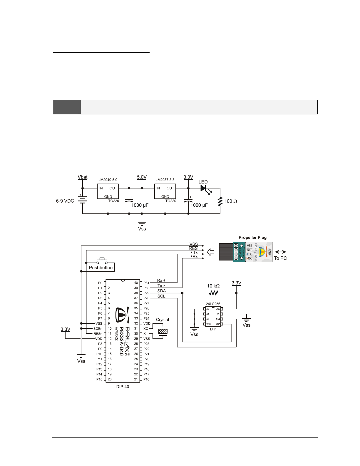
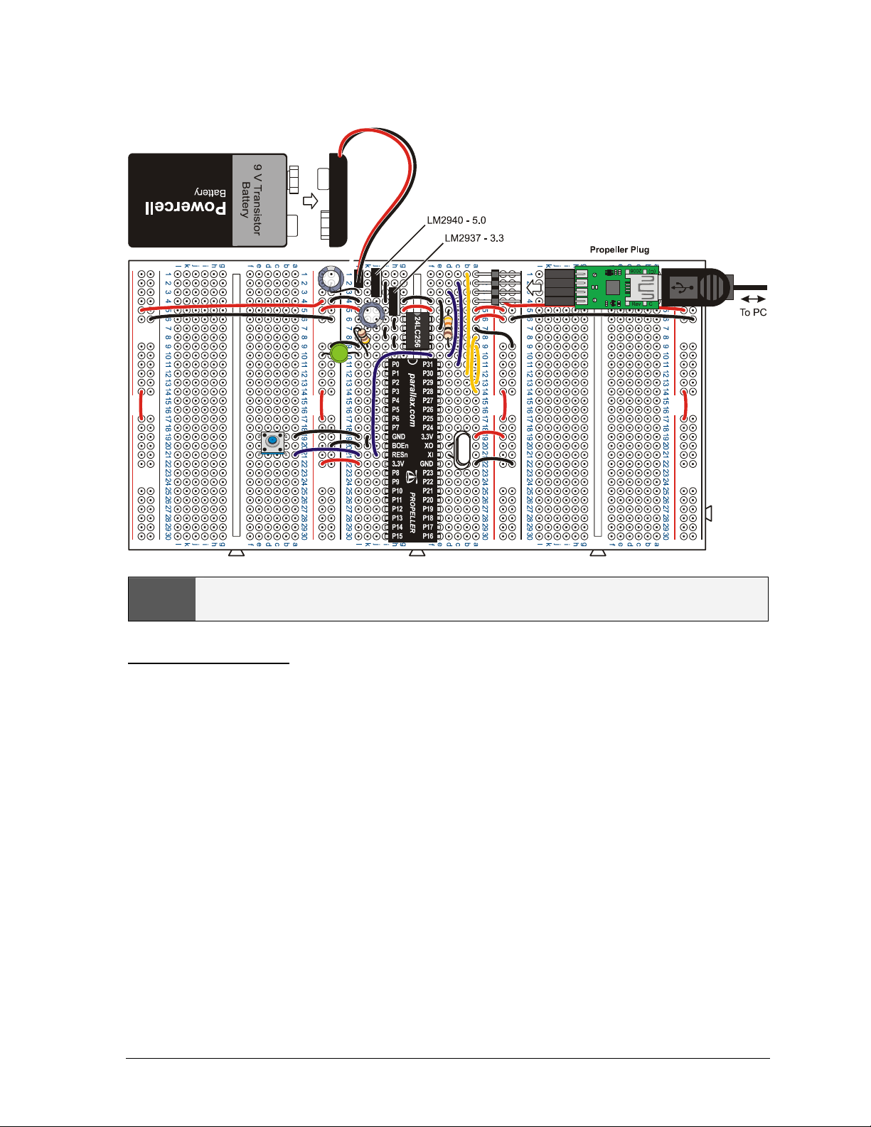
Figure 2 shows a schematic of the PE platform, and Figure 3 shows a recommended wiring diagram.
Notice that the board in the wiring diagram is tight-wired, with all the wires cut to length to be flush
with the breadboard surface. This will make it easier to identify and remove loose-wired project
circuits without having to worry about potentially removing a part or wire that’s integral to the PE
Platform.
LRecommended reading: Propeller Manual v1.0 pages 13 - 17.
3Do not plug in the battery, Propeller Plug, or Propeller chip until instructed to do so.
3Connect the interlocking breadboards together as shown in Figure 3, making sure the
numbers and letters are oriented the same way as in the figure.
3Build the circuit in Figure 2, using Figure 3 as a placement guide. (Remember to leave out
the battery, Propeller Plug, and Propeller chip for now).
Figure 2: Schematic – Propeller DIP Plus Kit
Copyright © Parallax Inc. ●Application Note Title and Version ●11/2/2006 ●Page 5 of 12
Figure 3: Wiring Diagram – Propeller DIP Plus Kit
LSee it in color: This file is available in color as a free pdf download from the Propeller Education Kit (32305)
product page at www.parallax.com.
Connection Testing
It’s important to eliminate all wiring mistakes before connecting power to the PE Platform. By
double-checking your wiring and running a few simple tests, you can in many cases catch a mistake
that might otherwise have caused your system not to work or even damage your components. To
start, let’s look at the design of these breadboards since they are integral to all of the circuits.
Wiring
Each socket on each 12-column × 26-row prototyping breadboard has a letter for the column and a
number for the row. For example, the 9 V battery’s positive terminal wire plugs into the center
breadboard’s (L, 1) (column L, row 1) and its negative terminal plugs into (L, 2). The 2 × 26 power
rails’ rows line up with the numbers on the prototyping breadboards. Red and black lines indicate the
column designation in the power rails. For example, the coordinates of the LED’s anode is (RED, 10)
and the coordinates of the top-left capacitor’s negative terminal is (BLACK, 1).
The red and black lines on the power rails also indicate continuity for power distribution. Unlike the
prototyping breadboards, which are grouped into 6-socket-wide rows each with a metal bracket
underneath, the power rails have only three metal brackets. A single metal bracket connects the entire
column of sockets adjacent to the black line. This typically serves as a common ground, and each
negative rail is connected to the battery’s negative terminal on the PE Platform.

Copyright © Parallax Inc. ●PE Platform Setup v1.0 ●11/2/2006 ●Page 6 of 12
LVss and GND; Vdd and 3.3V: The Propeller chip’s GND pin is referred to as Vss in the Propeller Manual; Vdd
is +3.3 V.
The column adjacent to the red lines has two separate metal brackets underneath instead of just one.
The upper twelve sockets next to the red line are grouped together, but are not connected to the lower
twelve, and the break in the red line next indicates the break in continuity. The breadboard is designed
this way to accommodate two separate voltage supplies on the same power rail. This feature is not
used now, so all the positive power rails are shorted together with jumper wires. In later labs, you
may end up removing one or more jumpers for dual supply applications.
3Make a printout of Figure 3, and verify each connection by drawing over it with a highlighter
pen after you have checked your wiring against the diagram, matching the coordinates of
each socket against the coordinates shown in the figure.
3Verify that the LM2940 5 V regulator output capacitor’s negative terminal is connected to
(BLACK, 1) and that the LM2937 3 V regulator’s output capacitor’s negative terminal is
plugged into (K, 6) or (K, 7)
! WARNING: Reverse voltage across the electrolytic capacitors can cause them to rupture or in some cases
explode. The electrolytic capacitor’s negative terminals (denoted by a stripe with negative signs) should
always be connected a lower voltage than their positive terminals. The electrolytic capacitors’ negative
terminals should be connected to the PE Platform’s negative power rail. This power rail is connected directly
to the battery supply’s negative terminal.
3Verify that the Power LED’s anode terminal is connected to (RED, 10).
Power Supply
3Connect the battery to the battery holder as shown in Figure 3. The power LED should glow
brightly. If it does not, unplug it immediately and go to Troubleshooting entry (2) on page 11.
3If you have a voltmeter, make sure to test the voltage difference between the four red/black
vertical power rails. Each should measure 3.3 V. If the voltage is incorrect, go to
Troubleshooting entry (3) on page 11.
3If you have an oscilloscope, examine the total power supply noise. With a 9 V battery input,
it should fall in the 50 mV neighborhood. (Example settings: 10 mV x 10 ms / division, AC
coupled, Auto Store enabled to capture and hold transients for several minutes.) What
happens to the total noise if you place the 0.47 µF capacitor across the power rails?
3Disconnect the battery from the clip!
LThe 0.47 µF capacitor should be placed across the 9 V power input if you are using a 6-9 VDC supply
that plugs into the wall.
Socket the Propeller Chip
3Identify the orientation of the chip’s and sticker’s reference notches against Figure 3.
3Affix the pinout sticker to the Propeller chip, making sure that the reference notch on the
sticker is oriented the same way as the reference notch on the chip.
3Disconnect both the battery and the Propeller Plug.
3Plug the Propeller chip into the breadboard, verifying its orientation as shown in Figure 3.
3Plug in the battery and verify that the LED power light glows brightly, as in your earlier
battery test. If it does not, disconnect the battery immediately, and go to Troubleshooting
entry (4) on page 11.

Copyright © Parallax Inc. ●Application Note Title and Version ●11/2/2006 ●Page 7 of 12
Programming Connection
3Disconnect the battery, and plug in the Propeller Plug onto the 4-pin header as shown in
Figure 3, with the label side down. The power LED on the breadboard should glow dimly. If
it does not, go to Troubleshooting entry (5) on page 11.
System Testing
The PE Platform is a microcontroller system very similar to the ones you’ll find in common products
and specialized equipment. The subcircuits and complete designs of many such products are
prototyped, tested, modified and refined using pluggable breadboards before they are mass-produced
as one or more printed circuit boards and housed in metal or plastic cases.
The PE Platform itself has a number of subcircuits, including the Propeller chip itself, voltage
regulators, oscillator, EEPROM, power indicator, reset button and programming connections. All
these subsystems need to be tested to make sure that the PE Platform will perform correctly through
the upcoming labs. For these tests, a couple of simple circuits will be built on the PE Platform, and a
test program will be downloaded to and executed by the Propeller chip. By modifying both the test
circuit and test program, you will be able to verify all the PE Platform’s subsystems.
Test the Programming Connection
The first test uses the Propeller Tool software’s Identify Hardware feature. The battery should be
connected, and the Propeller Plug should be connected to the 4-pin header and your PC via the USB
cable.
3Open the Propeller Tool, then from the Run menu select Identify Hardware… (or Press F7.)
An information window will appear with one of two messages:
•“Propeller Chip version 1 found on COM…”
•“No Propeller Chip found on any COM port. Scanned COM…”
When this feature is used, the Propeller Tool searches the available COM ports for a serial connection
to a Propeller chip. If the “Propeller…found…” message appears, it verifies three things: (1) The
USB virtual com port (VCP) driver is properly installed, (2) the Propeller Plug is functioning and
connected to the PC’s USB port, and (3) the PE Platform’s 4-pin Propeller Plug port is correctly
wired to the Propeller Chip. On the other hand, if the “No Propeller…found…” message appears,
there is a problem somewhere in the communication stream. In that case, Troubleshooting entry (6)
on page 11.
Test Circuit Parts List
For the next test circuits, you will need the following parts from the PE Project Parts bag:
(1) LED - Red, green or yellow
(1) Resistor - 100 Ω
(1) Resistor – 10 kΩ
(1) Pushbutton
(4) Jumper wires
Copyright © Parallax Inc. ●PE Platform Setup v1.0 ●11/2/2006 ●Page 8 of 12
Build the Test Circuit
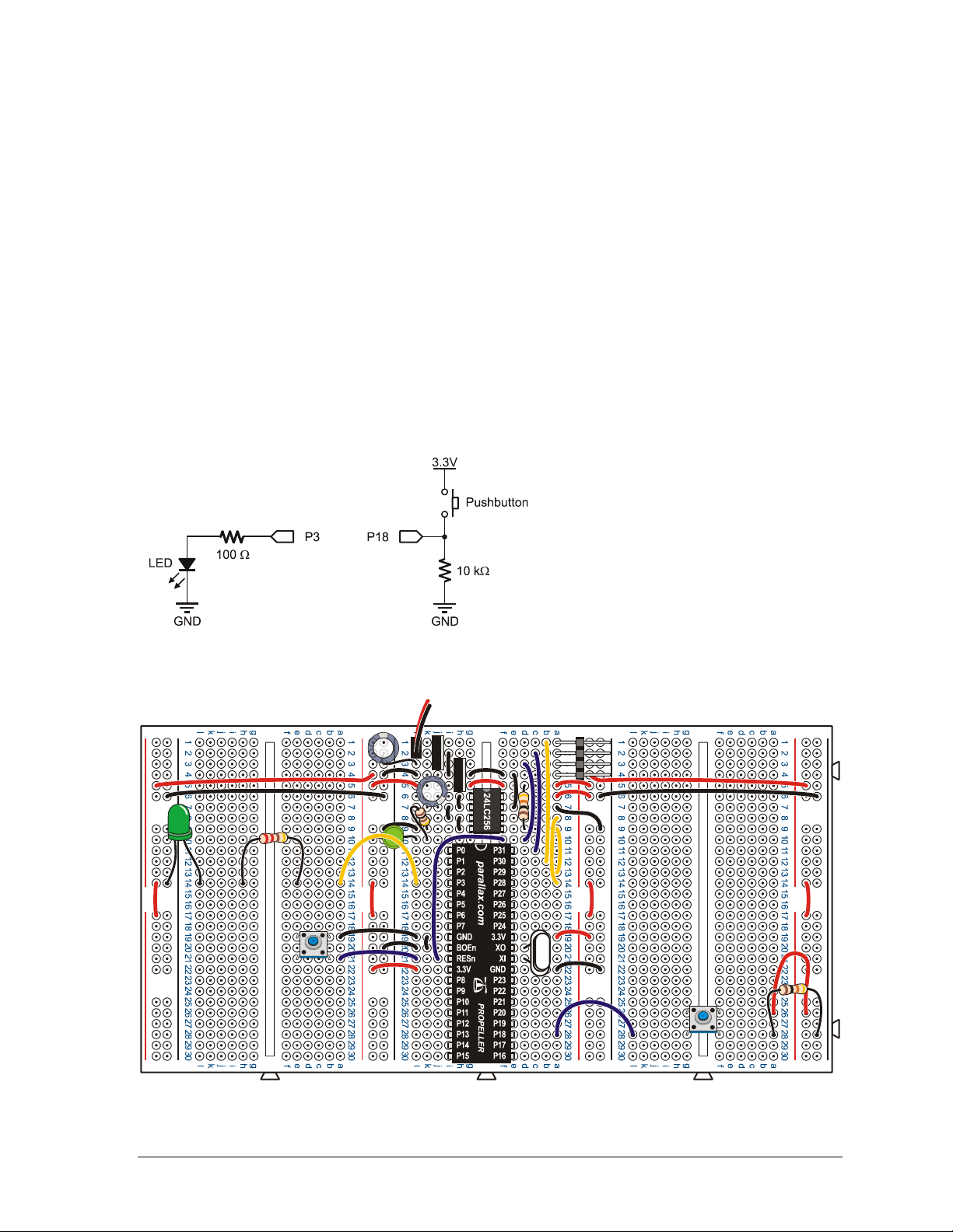
The circuit shown in Figure 4 and Figure 5 will provide a means of testing the Propeller chip’s I/O
pins as both inputs and outputs. If any of the checklist instructions do not work, go to
Troubleshooting entry (7) on page 12.
3Build the circuit shown in Figure 4 and Figure 5.
3Connect the 9 V battery
3Disconnect the LED wire from (L, 14) in Figure 5, and plug it into (RED, 13) on the power
rail between the center and left prototyping breadboards. The LED should light. If it doesn’t
double check your wiring, and especially check if the LED is plugged in backwards.
3Disconnect the wire from (RED, 13), and plug it into (RED, 12) on the leftmost power rail.
The LED should glow again.
3Disconnect the LED wire from (RED, 12) and reconnect it to the Propeller chip’s P3 I/O pin.
For this, you’ve got a choice of (L, 4), (K, 4), or (I, 4).
Figure 4: Test Circuit Schematic
Figure 5: Test Circuit Wiring Diagram
Copyright © Parallax Inc. ●Application Note Title and Version ●11/2/2006 ●Page 9 of 12
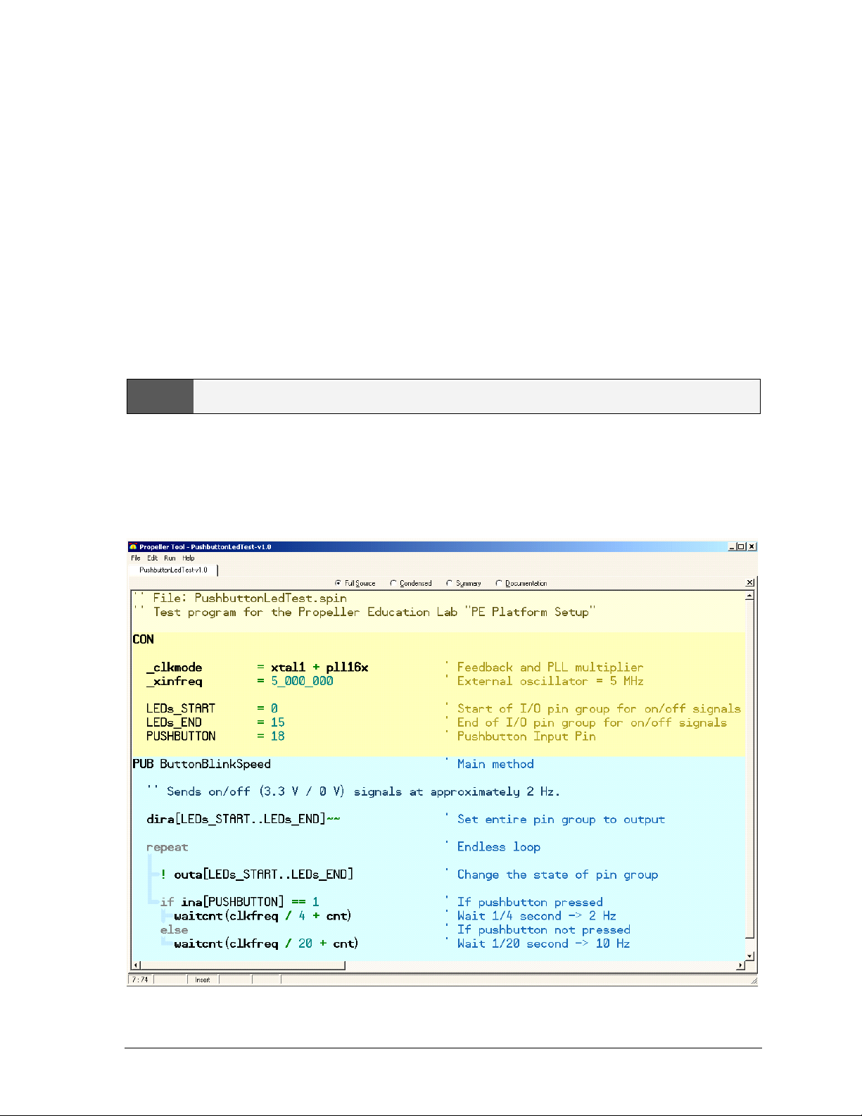
Test Program – PushbuttonLedTest.spin
This program will test the PE Platform’s EEPROM and external oscillator circuits as well as the I/O
pins as outputs, and you will modify it to test the I/O pins as inputs. For a new, factory-tested
Propeller chip the I/O pin testing may seem unnecessary, however, if this platform was used by a
student during the previous semester, or you purchased the kit used, it will be especially important.
In any case, subsystem and I/O pin testing before building experimental circuits is a good engineering
habit.
As written, PushbuttonLedTest.spin flashes an LED connected to any I/O pin on the Propeller chip’s
left side (P0 to P15), at a rate of 10 Hz if the pushbutton connected to P18 is not pressed, or at 4 Hz if
it is pressed. The fact that the LED blinks confirms the oscillator is working properly, since the
program causes the Propeller chip to use it for a clock signal. Next, the lead that connects P3 to the
LED circuit can be connected to P0, then P1, etc, through P15, and it should blink at 10 Hz at each
probe point, or 2 Hz if the button is pressed. This will test the output function of those pins.
LHow PushbuttonLedTest.spin works will be explained in later labs.
When the Propeller Tool’s Identify Hardware… feature works, it indicates that the transmit, receive
and reset wiring is all correct. If you have confirmed this, you will be able to download programs to
the Propeller chip’s RAM using the Run →Compile Current →Load RAM feature (F10). However,
we will use PushbuttonLedTest.spin to test is whether the EEPROM was correctly wired by using the
Propeller Tool’s Load EEPROM feature (F11).

Copyright © Parallax Inc. ●PE Platform Setup v1.0 ●11/2/2006 ●Page 10 of 12
LYou can download PushbuttonLedTest.spin from the Propeller Education Kit product page at
www.parallax.com. Then, simply drag and drop it onto the Propeller Tool’s Edit Pane to open it.
3Open PushbuttonLedTest.spin into the Propeller Tool, or type it in. If you type, be careful to
indent each line exactly as shown.
3Click the Propeller Tool’s Run menu and select Compile Current →Load EEPROM (F11).
The Propeller Communication window will appear briefly and display the progress. If it closes after
the “Verifying EEPROM” message, then the download was successful. If instead an error window
opens that reads “EEPROM programming error...”, refer to Troubleshooting entry (8) on page 12.
3Verify that the LED flashes on/off rapidly, at 10 Hz.
3Press and hold the pushbutton down, and verify that the LED flashes slower, at only 4 Hz.
3If everything worked as anticipated, go on to I/O Pin Tests below. If it did not work, go to
Troubleshooting entry (9) on page 12.
I/O Pin Tests
If you are inheriting this platform from a student who has already taken the class you are starting, it is
especially important to take some time now to confirm all the I/O pins are functioning correctly, both
as outputs and inputs. We will use the LED circuit to test each of the I/O pins’ output function on the
Propeller’s left side (P0 to P15). Since they all send the same signal as P3, each one should make the
LED circuit blink. After that, the pushbutton can be iteratively rewired to different I/O pins on the
right. PushbuttonLedTest.spin has to be modified and downloaded to the propeller to test each wiring
change. Once the left side has been tested as outputs and the right as inputs, the circuits can be
swapped so that the left side can be tested as inputs and the right side as outputs. If any of these tests
indicate that an I/O pin is faulty, refer to Troubleshooting entry (10) on page 12.
3Use the wire connecting P3 to probe P0 through P15. Each I/O pin should cause the LED
circuit to blink the same way it does when it’s connected to P3.
3Unplug the pushbutton wire at P18, and plug it into P16.
3Change the CON directive PUSHBUTTON from 18 to 16.
3Run the modified program and verify that a pushbutton connected to P16 still controls the
LED frequency.
3Repeat this procedure for P17, P19, P20, and so on, up through P27. Using F10 to download
to RAM instead of EEPROM will make this go faster.
3Disconnect the battery, and remove the pushbutton and LED test circuits from the board.
3Reconnect the battery and Propeller plug.
3Change the CON directives LEDs_START and LEDs_END from 0 and 15 to 16 and 27.
3Change the PUSHBUTTON directive from 18 to 13.
3Download the modified program.
3Disconnect the battery, then rebuild the test circuits on opposite sides of the board from
what’s shown in Figure 5. The pushbutton should be connected to P13, and the LED should
be used to probe I/O pins from P16 to P27.
3Reconnect the battery. The LED frequency should again be controlled by the pushbutton.
3Repeat the output tests for P16 to P27 and the input tests for P0 to P15.
3Also use the LED to probe the positive supply rails on the right side of the board.

Copyright © Parallax Inc. ●Application Note Title and Version ●11/2/2006 ●Page 11 of 12
An Empty Program for the Next Circuit
Whenever you change a prototype circuit, it’s a good idea to load a program that doesn’t do anything
to the I/O pins into the propeller. This reduces the risk of the Propeller chip inadvertently sending a
high signal to a circuit that is sending a low signal, or visa versa. In either case, if no resistor is in
series, it could result in a damaged Propeller chip, or a damaged circuit, or both. Loading an “empty”
program now in anticipation of building new circuits in the future will help protect your Propeller
chip. Ending your experiments this way is a good habit.
3Enter and run this program:
'' File: DoNothing.spin
PUB main ' Empty main method
Troubleshooting
Here are a list of symptoms and possible causes.
(1) If there is no apparent communication when you plug the Propeller Plug into the PC’s USB port,
follow the USB link on the Parallax home page. It will take you to the Installing USB Drivers
Page. If the steps on that page don’t fix the problem, follow the Troubleshooting link at the
bottom of that web page.
(2) If the PE Platform’s power LED did not light when the battery was connected:
a. The LED may be plugged in backwards. Check to make sure the cathode is connected to
the resistor and the anode is connected to the 3.3 V supply rail. In other words, the pin
coming out by the flat spot at the base of the LED’s round plastic housing should be
plugged into (L, 10), and the other pin should be connected to (RED, 10).
b. The battery leads may be plugged into the breadboard backwards. The battery’s +
terminal should connect to (L, 1) and the – terminal should connect to (L, 2).
c. There could be a wiring mistake causing a short circuit from one of the supply voltages to
ground. If you don’t have a multimeter, start visually checking your wiring again. With
a multimeter, you can check the resistance between the battery’s negative terminal, and
the 3 V power rail. Repeat for 5 V regulated output (G, 3) and for the battery inputs (G,
1). If any of these shows less than 1 Ω, that supply voltage has been shorted to ground.
(3) If the voltage across the power rails is not 3.3 V, the most common culprits are faulty wiring and
a faulty meter. If your meter is a lesser-quality model or has been subject to heavy use by other
students, check it against a known voltage before trusting its measurements. Assuming the
voltmeter’s measurements are correct, check wiring, part placement, and part orientation.
(4) If the Power LED does not light when you plug the battery in after socketing the Propeller chip,
check for wiring errors to its pins. If a wire terminates at a row that is shared with a Propeller
chip I/O pin, it’s a prime suspect.
(5) If the Power LED does not glow faintly when you connect the Propeller Plug to the 4-pin header,
double-check the wiring of the header. The header should be placed in (A, 1) through (A, 4). The
TX pin of the Propeller Plug, (A, 2) must be connected to P31 of the Propeller chip, which is
accomplished with the jumper wire connecting (C, 2) and (C, 11).
(6) Common causes of the “No Propeller Chip found…” message are:
a. Battery disconnected. Connect the battery.
b. Propeller Plug plugged in upside down. The parts side of the Propeller plug should be
facing up, and the logo side with the socket labels should be facing the breadboard.
c. Propeller Plug not plugged in to USB port.

Copyright © Parallax Inc. ●PE Platform Setup v1.0 ●11/2/2006 ●Page 12 of 12
d. Propeller chip not fully socketed. The underside of the Propeller chip should be flush
with the top of the breadboard. If not, make sure all the pins are lined up with the
breadboard holes, then press down firmly on the Propeller chip.
e. FTDI USB drivers not installed. See entry (1) in this section.
f. Supply voltages – if you didn’t check the voltages with a voltmeter, it’s time to get one
and do that. If the supply voltages are incorrect, see entry (3).
g. Propeller chip plugged in upside down. Check the top of the propeller chip, under where
the semicircle is on the sticker. Is the chip’s reference notch there? The reference notch
should be on the end of the chip that is closest to the EEPROM and voltage regulators, in
the neighborhood of row 11, not row 30.
(7) If the LED does not light up when you plug the jumper wire into (RED, 13), the polarity on the
LED may be backward. Check to make sure the LED’s cathode is connected to a socket on the
power rail next to the black line. If the LED did not light up when probing the power rail on the
left, check the jumper that connects the red column between the left and center breadboards to the
red column on the far left power rail.
(8) If you get an “EEPROM programming error…” message when you use the Propeller Tool’s Load
EEPROM feature, check the various EEPROM connections. Also verify that Pin 1 of the
EEPROM, denoted by a dot on the case, is inserted into (G, 6), that is, make sure it is not inserted
upside down. Also, verify that all the pins on the left side of the chip are tied to GND.
(9) If you hand entered the program, download it from the Propeller Education Kit page instead.
Open it with the Propeller Tool software, and use F11 to download it to EEPROM. This will
eliminate the possibility of a clerical error during program entry. If the LED does not start
flashing, check the oscillator connections (XO and XI). If the LED circuit turns on and stays on
with no blinking, there may be an issue with the power supply. If you have not already done so,
try entry (3) in this section.
(10) If the LED or pushbutton tests indicate a bad I/O pin, take a close look at the pin and verify
that it did not bend under the chip instead of inserting into the socket. Propeller microcontrollers
are 100% factory tested before shipment and it is not typical that the chip is defective; please
contact Parallax Tech Support if you have a potentially defective part. Also, replacement
Propeller DIP chips can be purchased individually from Parallax if you do happen to damage
yours. If you wish to return your product because of a manufacturer’s defect or because it does
not meet your needs, please see the Warranty Policy at www.parallax.com for details.
Tech Support Resources
Parallax Inc. offers several avenues through which to gain free technical support services:
•Email: [email protected]
•Fax: (916) 624-8006
•Telephone: Toll free in the U.S: (888) 99-STAMP; or (916) 624-8333, between the hours of
7:00 am and 5:00 pm Pacific time.
•Forums: http://forums.parallax.com/forums/. Here you will find an active forum dedicated to
the Propeller chip, frequented by both Parallax customers and employees.
Table of contents
Popular Educational Equipment manuals by other brands


VICEDO MARTI
VICEDO MARTI PRACTI-BABY PLUS PACK quick start guide

Prestan
Prestan PP-IM-100M Use and Care Instructional Sheet

PHYWE
PHYWE Cobra SMARTexperiment operating instructions

KOKEN
KOKEN LM-083 instruction manual

John Lewis
John Lewis Illuminated globe quick start guide

ARRL
ARRL ETP Solder 101 Construction manual

Quanser
Quanser QNET 2.0 HVAC user manual

Simulaids
Simulaids Economy Sani-Man DIRECTIONS FOR ASSEMBLY

Rompa
Rompa 18663 manual

Rompa
Rompa ADUKI 20277 quick start guide

Aircatglobal
Aircatglobal Virtual Fly SOLO GA user manual

Learning Resources
Learning Resources STEM Explorers Motioneering LER 9308 quick start guide