Bulletin TI-LCMS-SF5000J Installation, Operation and Maintenance Manual
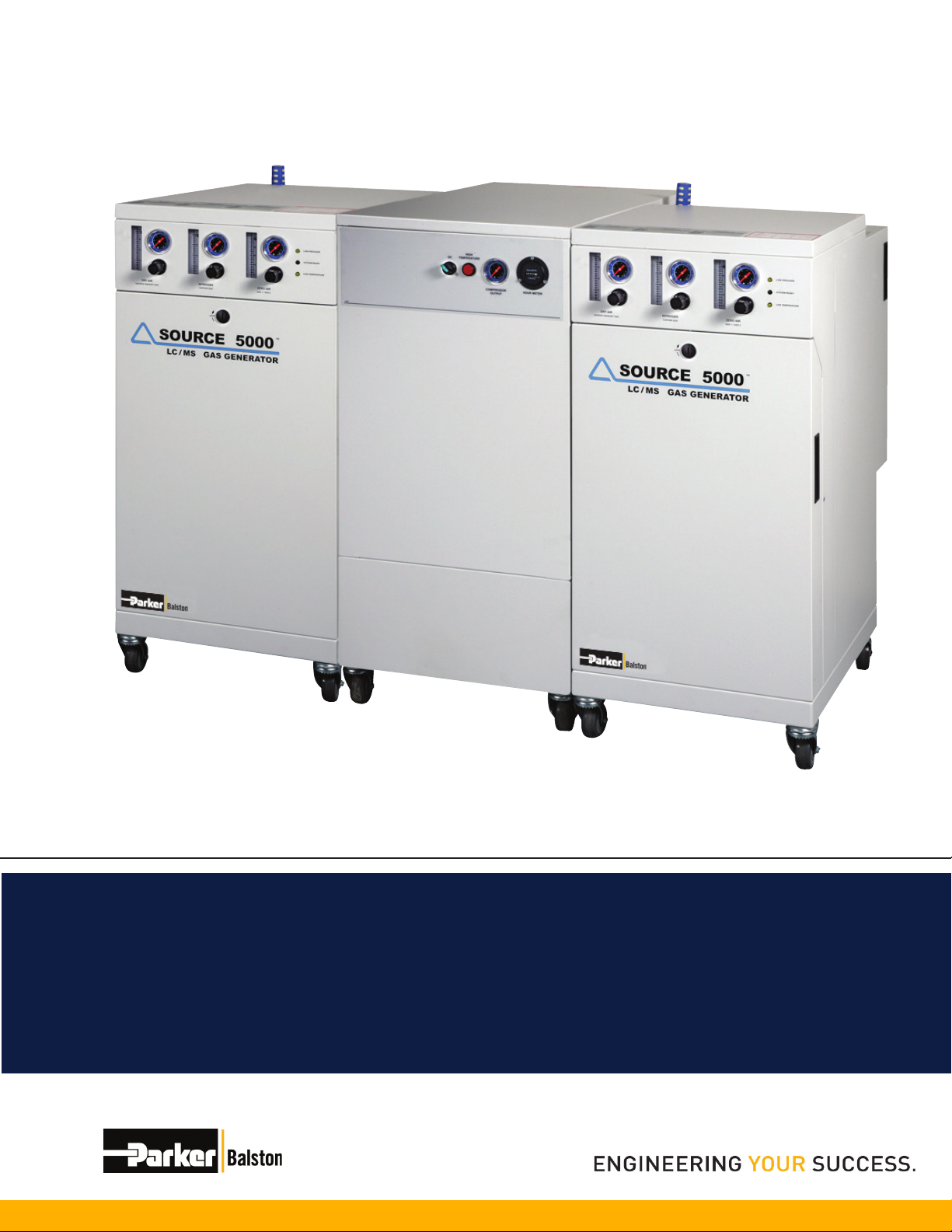
Super Flow Tri-Gas Generators
www.labgasgenerators.com
8
1-800-343-4048
The generator is for indoor use only. Do not install outdoors. The ambient temperature of
the air surrounding the generator should not exceed 90°F (32°C). If the compressor is located
in a totally enclosed room without ventilation, an exhaust fan with access to outside air must be
installed. Do not locate the compressor where hot exhaust air from other heat generating units
may be drawn into the compressor. The area should be free of excessive dust, toxic or ammable
gases, solvent fumes, and moisture.
Chlorinated hydrocarbon compounds and chlorouorocarbons (or freons) will permanently contam-
inate the hydrocarbon catalyst module in the generator. Extreme care should be taken to ensure
that these compounds are not present in the air supplying the compressor.
The hydrocarbon catalyst module can also be contaminated by high concentrations of lead, sulfur,
or phosphorous compounds, heavy metals, and long chain polymers. Care should be taken to
avoid introducing these compounds into the Generator. Specically, assure that none of these
compounds are stored near the inlet to the compressor supplying the system with compressed air.
If these compounds are present, the intake for the compressor should be vented to the outdoors.
If any potentially damaging hydrocarbons, chlorouorocarbons, chlorinated solvents or other simi-
lar components are used in close proximity to the compressor, an auxiliary hydrocarbon scrubber
(P/N 76080) should be installed directly upstream from the generator (see Recommended Acces-
sories on page 10).
The LCMS-SF5000 creates minimal noise during operation. The noise generated is about 49 dB
at one meter. Periodically there is an air discharge noise from the drain port eliminating accumu-
lated uids in the prelters and receiver tank. The noise and heat generated by the unit should be
considered when selecting an installation location. A silencer kit is included for the drain discharge
noise. There is also a pump “burp” noise lasting a few seconds each time the compressor shuts-
off depressurizing the pump during the off cycle.
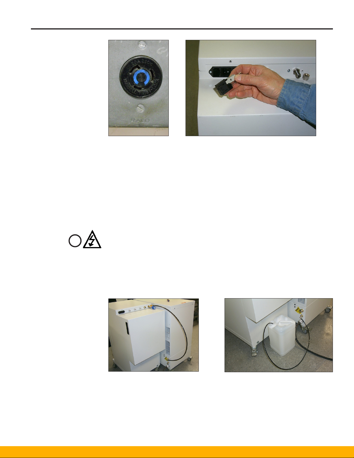
For the NA Model: The LCMS-SF5000 generator requires three electrical power outlets: The
compressor cabinet requires one dedicated grounded 208 to 254 VAC, 60 Hz, single phase,
minimum 20 Amp. circuit breaker with a NEMA L6-20R receptacle (see gure 9). Parker requires
purchasing a step-down transformer if your facility voltage is 255 or higher, or a step-up
transformer if your voltage decreases below 208. See the accessory section on page 27. The
two Tri-Gas generator cabinets each require one 120VAC, 60Hz, single phase, 15Amp circuit with
a NEMA 5-15R receptacle. Main supply voltage uctuations must be within ±10% of the nominal
main supply voltage.
For UK, EU Models: The compressor, rated at 230V, 50 Hz, single phase, 13A fully loaded instal-
lation each require the following electrical setup:
1 The supply line should be dedicated to the compressor. No other equipment should operate us-
ing the same line.
2The service should be capable of carrying 20 amperes. The wire gauge should be sized accord-
ingly.
3The service should be protected by a minimum 20 amperes circuit breaker. The value is based
on the application/equipment requirements as well as the electrical components’ tolerance and
uncontrollable external variables.
The two Tri-Gas Generators, rated at 220 VAC, 230 VAC or 240 VAC, 50/60 Hz, single phase, 2A
installation each require the following electrical setup:
1The supply line does not need to be dedicated to the generator.
2The service is of adequate ampere rating.
3 The voltage selector is set to match the local power supply (220V, 230V or 240V).
4The provided cordset rating is 10A/250VAC. The cordset should not be replaced with an inad-
equately rated cordset.
The electrical schematics for the compressor are shown in Figures 54, 55, and 56 on pages 34,
35, and 36 (Back Cover).
For compressors shipped after 10/1/2010 which look like Figure 15, use Electrical Schematic 3 on
the Back Cover (Page 36) of this manual.
Utilities