Bulletin TI-H2PD-K Installation, Operation and Maintenance Manual
H2PD-150 and H2PD-300 Hydrogen Generators
www.parker.com/igfg
7
1-800-343-4048
All installation, operation, and maintenance procedures for the Parker Balston Hydrogen
Generator should be performed by suitable personnel using reasonable care.
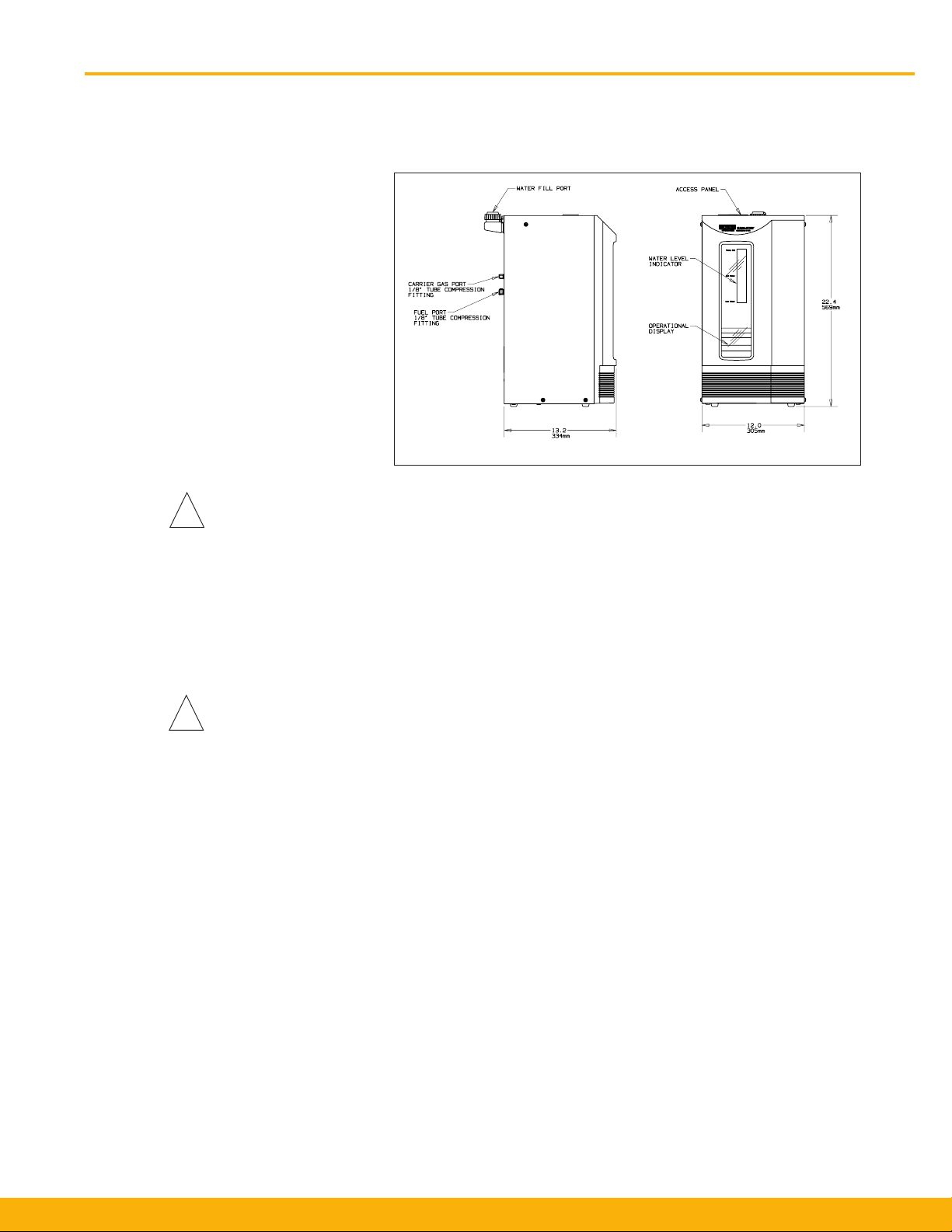
The Parker Balston H2PD-150 and H2PD-300 Hydrogen Generators are free-standing bench-top
units. Do not suspend the hydrogen generator from the wall or ceiling. Its weight and size
could pose a falling hazard. The generator should be located indoors, protected from severe
weather conditions, and free from excessive ambient dust or dirt. Do not install the generator
outdoors.Theambienttemperatureoftheairsurroundingthegeneratormustbebetween50°Fand
104°F(10°Cand40°C).Placethehydrogengeneratorinanuprightposition,onalevelsurface,in
close proximity to both the electrical power supply and the equipment requiring the hydrogen supply.
The Parker Balston Hydrogen Generator weighs 58 lbs. (26 kg.) Use proper equipment and lift-
ing techniques for transporting this equipment to its installation location. The hydrogen generator
isintendedtoremainstationarywhenlledwithwaterandelectrolyte.Ifnecessary,thegenerator
may be relocated over shortdistanceswhenlled.Do not grasp the front panel when moving
the hydrogen generator. Lift the generator by the metal case only. The generator should remain
uprightwhenmoved.Forlongdistancemoves,thegeneratormustbeshutdownanddrained.(See
Shutdown section of this manual.)
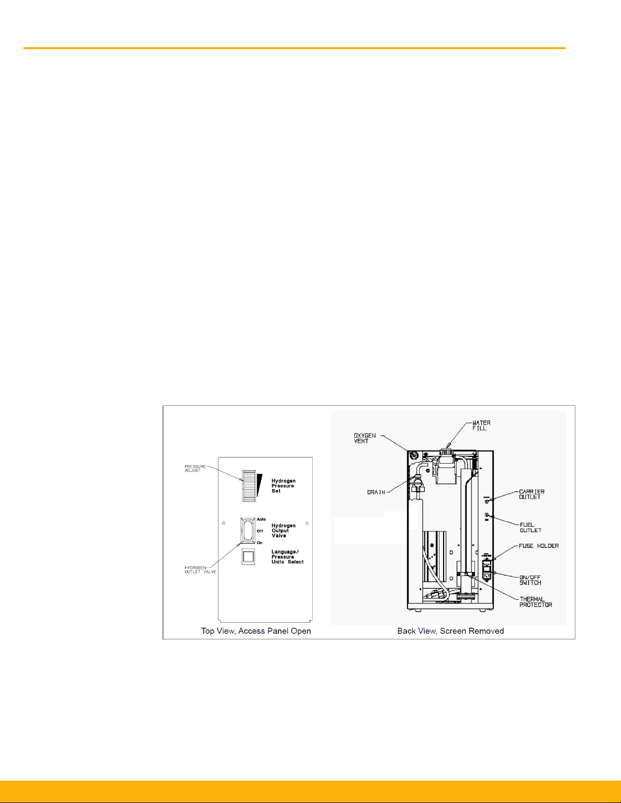
Power - The Parker Balston Hydrogen Generator may be operated by a 120 VAC or a 230 VAC,
50/60 Hz power supply. (Note: Main supply line voltage must be within ±10% of the nominal
rated voltage for the generator.) See product label on the rear panel of the hydrogen generator for
factory voltage setting. To connect the generator to the power supply, simply plug the female end of
the electrical cord into the receptacle on the right side of the generator, and the opposite end into a
three-pronged earthed power receptacle.
Note: Protect the generator from sudden, transient uctuations in electrical power by using
a surge suppressor. Parker recommends using a surge suppressor meeting the following
specications:
Joule Rating 1000 or greater
Surge Amps 84,000 or greater
Max Noise Reduction 80+ (db)
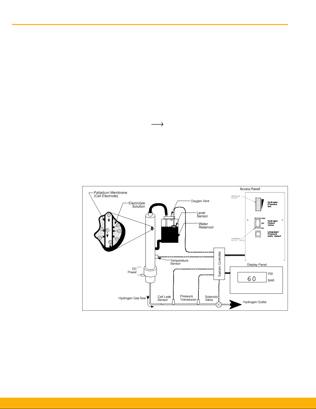
Deionized Water - The Parker Balston Hydrogen Generator must be supplied with deionized water
on a regular basis. The water should be 5 Megohm-cm, or better quality deionized water.
Caution: Do not use tap water or deionized water with less than 5 Megohm-cm resistivity.
Metallic ions and suspended solids present in substandard water may poison the palladium
membrane, rendering the cell inoperable. If the generator is operated with any liquid other
than 5 Megohm-cm (or better) deionized water, the warranty will be void.
Piping - The outlet connections for the Parker Balston Hydrogen Generators are a 1/8” compres-
siontting.Alltubingandttingsdownstreamfromthehydrogengeneratorshouldbecleanstain-
lesssteeltominimizecontaminationofthehydrogenstream.Ifcoppertubinghasbeenusedwith
hydrogen in the past and has yielded acceptable results, there is no need to alter an existing piping
congurationtoinstalltheParkerBalstonHydrogenGenerator.Thepipingcongurationforthe
hydrogen delivery system should include a means for venting subpurity hydrogen generated during
system warm-up. This may also be accomplished by disconnecting the downstream instruments.
Parker strongly recommends the installation of a shutoff valve and pressure regulator at the process
orinstrumentbeingsuppliedwithhydrogenfromthegenerator.(Iftheprocessorinstrumenthasits
own internal shutoff valve and pressure regulator to isolate it from the hydrogen line, this installation
is unnecessary.)
Forconvenience,thehydrogenstreamfromtheParkerBalstonHydrogenGeneratorismanifolded
for carrier and fuel gas applications. There is no difference in hydrogen quality between the two
ports.Thegeneratorisshippedwitha1/8"ferrulettingonthefuelgasportandapipeplugonthe
carriergasport.Ifhydrogenisbeingusedasacarriergas,simplyremovethepipeplugfromthe
carrier port and replace with the nut and ferrule supplied in the accessories bag. (Note: If one port
is not being used, it must be capped.)Thecombinedowfromthecarrierandfuelgasportsmust
not exceed the capacity of the generator.
Location
Transporting
Utilities
Piping for Carrier Gas and
Fuel Applications
Installation