Parker Compumotor RP240 User manual

Chapter
➀
Installation
1
C H A P T E R ➀
Introduction
Chapter Objective
The information in this chapter will enable you to:
❏Understand the product's basic functions & features
Product Description
The RP240 is designed to operate as an operator interface for Compumotor's
Extended X (the SX Indexer/Drive, ZX Indexer/Drive, and Model 500 Indexer)
and 6000 Series products (6200 Indexer and 6250 Servo Controller). The
RP240 operates strictly as a dumb terminal. No programming of any kind
can be accomplished using the RP240. The RP240 is controlled by commands
available in the Extended X and 6000 Series command sets. The commands
allow the programmer to create a program (within the Extended X or 6000
Series product) to prompt an operator for numeric information, read
function keys, display variables and text, and control the 8 LEDs located on
the RP240.
If the RP240 is not used with the SX, ZX, Model 500, 6200, or 6250, ASCII
command strings sent directly to the RP240 can be used to control the
functions contained within the RP240 (refer to Chapter ➅Direct Control of
the RP240).
RP240 Features
❏Operates directly with Compumotor's SX and ZX Indexer/Drives, and the Model
500 Indexer
❏Operates directly with Compumotor's stand-alone 6000 Series products (6200
and 6250)
❏Can be used with any controller capable of transmitting ASCII strings across
RS-232C
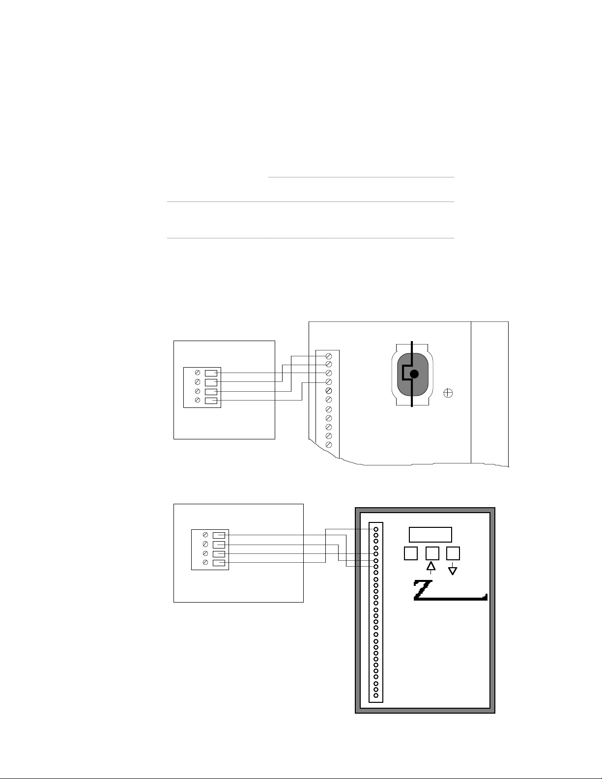
❏Screw terminal connections for easy wiring
❏Optional NEMA specification ratings (standard RP240 is NEMA 12, optional
RP240-NEMA4 meets NEMA 4 & NEMA 12 specifications when panel mounted.)
❏Adjustable contrast for the LCD display
❏Eight independent LEDs
❏Numeric and function key data entry
❏Uses less than 100 mA of current at 5VDC

Chapter
➁
Getting Started
3
C H A P T E R ➁
Getting Started
Chapter Objectives
The information in this chapter will enable you to:
❏Verify that each component of your system has been delivered safely
❏Become familiar with system components and their interrelationships
What You Should Have
Inspect your RP240 shipment upon receipt for damage to its shipping
container. Report any damage to the shipping company as soon as possible.
Parker Compumotor cannot be held responsible for damage incurred in
shipment. The items listed in the table below should be present and in good
condition. RP240 RP240-NEMA4
Description Part # Part #
RP240 Main Unit RP-240 RP-240 NEMA4
Gasket 58-009135-01 58-013341-01
RP240 User Guide 88-012156-01 88-012156-01
CAUTION
Do not use sharp objects such as pencils, screw drivers, etc. on the front panel it will
cause permanent damage to the membrane and will void the warranty.
Basic System Configuration
F1 F2
MENU
RECA LL
1
23
4
5
6
7
89
0
.
+/-
C/E
ENTER
CONTRAST
INCREASE
CONTRAST
DECREASE
PAUSE
CONTINUE
STOP
POWER
F3 F4 F5 F6
1
2
3
4
5
6
7
8
RP240
Compumotor

4
RP240 User Guide
Wiring Connections
The following figure illustrates the RS-232C and power; connector. This
connector is located on the back of the RP240.
☞Helpful Hint:
RP240 Back Panel
Gnd
Rx
Tx
+5 V
Back Panel
RS-232C
Connector

Chapter
➂I
nstallation
5
C H A P T E R ➂
Installation
Chapter Objectives
The information in this chapter will enable you to:
❏Mount the RP240 properly
❏Wire the RP240 correctly
❏Verify that the complete system is installed properly
Environmental Considerations
☞Helpful Hint:
For more on NEMA
standards, contact the
National Electrical
Manufacturers
Association
, 2101 L
Street Northwest,
Washington, D.C.
20037. Ask for NEMA
Standards Publication
No. 250 Enclosures for
Electrical Equipment.
The RP240 is designed to be mounted to a door, on a panel front, desk, or
carried by hand. The RP240-NEMA4 is designed to be flush mounted in a
door. Both the RP240 and RP240-NEMA4 are designed to work in
temperatures up to 122°F (50°C). NEMA 12 specifications are achieved when
the RP240 is door or panel mounted using the provided gasket. NEMA 4
specifications are achieved when the RP240-NEMA4 is door or panel
mounted using the provided gasket. NEMA Type 12 enclosures provide a
degree of protection against dust, falling dirt, and dripping non corrosive
liquids. NEMA Type 4 enclosures provide a degree of protection against
windblown dust and rain, splashing water, and hose-directed water.
Electrical Noise Minimize the potential for electrical noise before installing the RP240
rather than attempting to solve such problems after installation. You can
prevent electrical noise by observing the following installation precautions:
❏Do not put high-voltage wires and low-level signals in the same conduit
❏Do not expose wiring (shield all wires)
❏Ensure that all components are properly grounded
Airborne Contaminants
Contaminants that may come in contact with the RP240 should be carefully
controlled. Particulate contaminants, especially electrically conductive
ones (such as metal shavings), can damage the RP240.

6
RP240 User Guide
System Mounting
RP240 Door MountTo mount the RP240 operator panel to the door of an enclosure, or on a panel,
follow the steps below.
➀Drill four holes as shown in the following figure
➁Remove the bayonet mounts (screws and standoffs) and rubber feet from the
back of the operator panel (save the screws for mounting).
➂Put one screw through the door.
➃Put the gasket (provided) on the screw.
➄Put the operator panel onto the screw and tighten.
➅Align the panel and gasket and insert the remaining three screws.
➆Connect the 4 wires between the operator panel and the Extended X or 6000
Series product. See RP240 Connections later in this chapter.
6.90
0.90 6.90
0.60
1.95 0.83
Mounting Holes
0.187 Dia. (4 Plcs)
GND
Rx
Tx
+5V
Enclosure
Door Gasket

Chapter
➂I
nstallation
7
RP240 Dimensions
The following figure shows the dimensional drawing for the RP240.
Mounting holes and their dimensions are given.
Compumotor RP240
1.50
8.70
8.10
6.90
0.90 6.90
0.60
1.95 0.83
0.76 0.60 Interface Connector
Location
Mounting holes
8-32 UNC (4 Plcs)
GND
Rx
Tx
+5V
RP240-NEMA4 Door Mount
To mount the RP240-NEMA4 operator panel through the door of an
enclosure, or in a panel, follow the steps below.
➀Cut an 8.3 inch vertical by 8.9 inch horizontal hole in the door of the enclosure
or panel as shown on the following page.
➁Drill eight holes in the locations shown.
➂Place the gasket (provided) on the RP240-NEMA4.
➃Put the operator panel through the door and tighten the eight nuts provided.
➄Connect the 4 wires between the operator panel and the Extended X (SX, ZX, or
Model 500) or the 6000 Series (6200 or 6250) product.
The following figure shows the dimensional drawing for the RP240-NEMA4.
Mounting studs and the required diameter clearance holes are given.
9.95
9.35
1.55
0.25
9.40
7.45
1.950.28
8.80
7.15
1.65
0.28
0.53
0.187 Diameter Clearence Holes
For #8-32 UNC-2B Studs (8x)
8.90 (Recommended Panel Cutout)
0.53 8.30 (Recommended Panel Cutout)
GND
Rx
Tx
+5V
RP240
Compumotor

8
RP240 User Guide
Cutout in Cabinet Door
Gasket
RP240 Nema 4 Housing
Wiring Guidelines
☞Helpful Hint:
All earth ground
connections must be
continuous and
permanent.
Compumotor
recommends a single-
point grounding setup.
Proper grounding of electrical equipment is essential to ensure the safety of
personnel. You can reduce the effects of electrical noise due to
electromagnetic interference (EMI) by proper grounding. All Compumotor
equipment should be properly grounded. A good source of information on
grounding requirements is the National Electrical Code published by the
National Fire Protection Association of Boston, MA. In general, all
components and enclosures must be connected to earth ground through a
grounding electrode conductor to provide a low impedance path for ground
fault or noise-induced currents.
RP240 Connections
The RP240 operator panel is connected to the Extended X (SX, ZX, or Model
500) and 6000 Series (6200 or 6250) products by means of a four wire shielded
cable (user supplied). For cable lengths up to 50 feet long, Compumotor
recommends using 20 AWG wire. Cable lengths longer than 50 feet are not
recommended. This in accordance with the Electronic Industries
Association (EIA) recommendations for RS-232C at 9600 baud.

Chapter
➂I
nstallation
9
To wire the RP240 to a 6000 Series product (6200 or 6250), connect the +5VDC
connection on the RP240 to the +5VDC source on the 6000 Series connector
labeled RP240. Connect the RP240 ground connection to the ground on the
6000 Series connector labeled RP240. Connect the RP240 Receive Data (Rx)
terminal to the controller's Transmit Data (Tx) terminal, and the RP240
Transmit Data (Tx) terminal to the controller's Receive Data (Rx) terminal.
Make all connections on the 6000 Series connector labeled RP240.
To wire the RP240 to an Extended X product, connect the +5VDC connection
on the RP240 to a +5VDC source capable of supplying 100 mA of current. You
must supply 5VDC ±2% to pin 1 of the RP240. You can use the 5VDC power
supplies on the SX, ZX, or Model 500 provided there is enough current
remaining. Current levels are shown in the table below.
Current Requirements
Available Encoder I/O RP240
SX 250 mA 150 mA 10 mA each 100 mA
ZX 500 mA 150 mA 0 mA 100 mA
500 500 mA 150 mA 0 mA 100 mA
Connect the RP240 ground connection to the ground of the +5VDC power
supply. Connect the RP240 Receive Data (Rx) to the controller's Transmit
Data (Tx), and the RP240 Transmit Data (Tx) to the controller's Receive Data
(Rx). Connect the RP240 only after you have programmed the controller for
operation with the RP240.
RP240 to SX Wiring Diagram
Rx
Tx
G
+5V
OPTO1
CW
CCW
HOME
OPTO2
REG
I1
AC Power
95-132VAC
50/60Hz
Compumotor
Gnd
Rx
Tx
+5 V
RP240 Rear Connector
RP240 to ZX Wiring Diagram
+5V
VOUT
ENBL
G
RX
TX
G
A+
A-
B+
B-
G
CW
CCW
HM
I1
I2
I3
I4
I5
I6
I7
O1
O2
O3
O4
G
SHLD
ENTER
I/O[1]
BRUSHLESS
SERVO DRIVE
SERIES
X
Gnd
Rx
Tx
+5 V
RP240 Rear Connector

10
RP240 User Guide
RP240 to Model 500 Wiring Diagram
Model 500 Indexer
INC
ENCODER
ABS/INC
ENCODER
MOTOR
DRIVER
Rx
Tx
GND
EARTH
RS232
Gnd
Rx
Tx
+5 V
RP240 Rear Connector A +5VDC power source
is available at pin 23 of
either 25-pin D
connector.
Pin 23—+5VDC
Pin 14—Ground
RP240 Connector Pin Out
The following table provides the pin out for the RP240 connector.
Pin In/Out Function Description
1 In Ground Logic Ground
2 In Receive (Rx) RS-232C Receive Data input
3 Out Transmit (Tx) RS-232C Transmit Data output
4 In +5VDC Input Power (100 mA minimum)
Installation Verification
6000 Series To verify the operation of the RP240 and the 6000 Series product to which it
is connected, apply power to the 6000 Series product. The RP240 display
should look similar to one of the following screens. If you are using an
Extended X product, go to the next section.
S
O
A
OUMCP TOM
OURN JG
R 6 200 INDEXER
DI PL Y ETC
OOUMCP TOM
C UANCE
R 6 200 INDEXER
RSS

Chapter
➂I
nstallation
11
Using the RP240 With An Extended X Language Product
☞Helpful Hint:
If you are using the
RP240 with a 6000
Series product, skip
this section.
Before continuing with this section, you should be familiar with the
Extended X Language product you will be using. An understanding of
programming sequences is important. Download the following program to
Sequence #100 in the Extended X Language product.
Command Description
>XE1ØØ Erase sequence #100
>XD1ØØ Begin definition of sequence #100
DCLRØ Clear all lines of the RP240 display
DPC1ØØ Cursor to line 1, column 0
DTXTTHIS_IS_A_QUICK_DEMO Display text at current cursor location
VAR1=FUN Wait for function key
DLED11111111 Turn on all LEDs
DCLRØ Clear all lines of RP240 display
DPC1ØØ Cursor to line 1, column 0
DTXTTHE_LEDS_WILL_TURN_OFF_IN_5_SECONDS Display text
T5 Wait 5 seconds
DLEDØØØØØØØØ Turn off all LEDs
DCLRØ Clear all lines of RP240 display
XT End sequence definition
>
Attach the RP240 after you have downloaded the above sequence correctly.
Cycle power. The following is displayed.
THIS SI A QUI CK DEMO
Press any function key to continue. After pressing any function key, all the
LEDs on the RP240 will turn on and the display will read as shown below.
THE DL T OFF I N SECOES URN 5 NDSWI LL
After 5 seconds, all the LEDs on the RP240 will turn off and the display will
be cleared.
This manual suits for next models
1
Table of contents