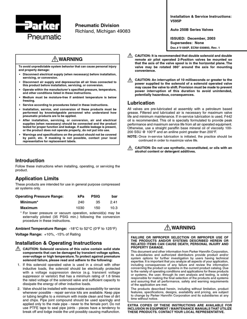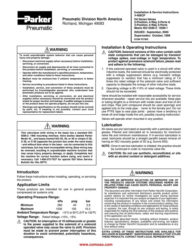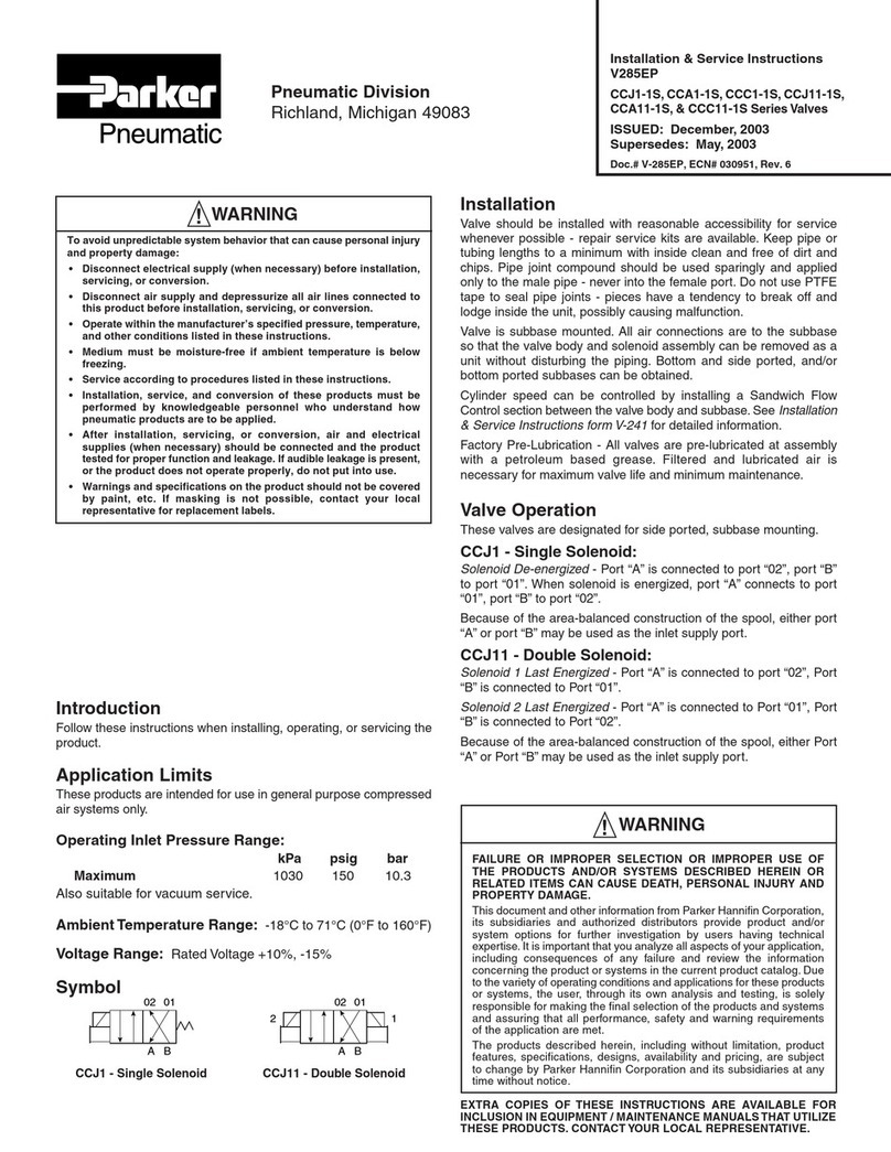
Pneumatic Division North America
Richland, Michigan 49083
Installation & Service Instructions:
V-650P
Flow Control Valves
1", 1-1/4" & 1-1/2" Pipe
ISSUED: July, 1999
Supersedes: 3250-7035 June, 1998
ECN# 9071
OperatingTemperatures:
-40°C to 82°C (-40°F to 180°F)*
Maximum Operating Pressures:
kPa psig bar
Maximum 1724 250 17.24
* Ambient temperatures below freezing require moisture-free
air. Ambient temperatures below freezing and above 180°F
require lubricants especially selected for suitability at these
temperatures.Pneumatic valves should be used with filtered
and lubricated air.
ANSI Symbol:
Installation & Operating Instructions:
Flow Control Valves are designed to provide an
adjustable
restriction
for varying or metering fluid flow in one direction
through the valve and Full Flow in the opposite direction through
the same valve.
For most double acting cylinder applications, two Flow Control
Valves should be used. This makes possible accurate and
independent control of cylinder piston speed in both stroke
directions. It is generally best to install Flow Control Valves in
the pipe lines between the Cylinder and Directional Control
Valve, as close to ports on the Cylinder as piping will permit.
Air flows through valve with minimum restrictions in direction
of arrow printed on label. Flow in opposite direction is metered,
depending on setting of Metering Needle.
Valve may be used for either
Meter-In Control
of air flow TO
Cylinder Port or
Meter-Out Control
of air flow FROM Cylinder
Port. For Meter-Out Control, install valve with Full Flow arrow
pointing TOWARD Port on Cylinder. For Meter-In Control, install
valve with Full Flow arrow pointing AWAY FROM Port on
Cylinder. Generally, best results are obtained with Meter-Out
Control.
Metered flow is adjustable. Clockwise turning of Metering
Needle (Item #4) reduces flow — Counterclockwise adjustment
increases flow. After obtaining desired flow by adjusting
Metering Needle, securely tighten Lock Nut (Item #1) to reduce
the possibility of changes from unauthorized personnel or due
to vibration.
Service Procedures:
!
CAUTION: Always shut off air supply and depressurize all
air lines connected to the valve before servicing unit.
1. Using a hex head wrench, loosen both set screws (Item
#11) at the bottom of the valve.
2. Unscrew and remove plug assembly (Item #9).
3. Remove spring (Item #7) and poppet (Item #8).
4. Remove body o-ring (Item #10) from plug assembly and
poppet o-ring (Item #6) from poppet and discard both
o-rings.
5. Unscrew and remove lock nut (Item #1).
6. Remove retaining ring (Item #2) and discard.
7. Unscrew and remove metering needle (Item #4) and
discard needle o-ring (Item #3).
8. Inspect the needle seat, poppet and poppet seat for nicks,
voids, pits and deep scratches. Replace the entire valve if
any of these irregularities are present.
9. Using a non-detergent hydrocarbon base oil or grease,
lightly lubricate all o-rings found in the service kit and
place them on their respective components.
10. Screw in the metering needle and install the new retaining
ring.
!
WARNING
To avoid unpredictable system behavior that can cause personal
injury and property damage:
• Disconnect electrical supply (when necessary) before installation,
servicing, or conversion.
• Disconnect air supply and depressurize all air lines connected to
this product before installation, servicing, or conversion.
• Operate within the manufacturer’s specified pressure, temperature,
and other conditions listed in these instructions.
• Medium must be moisture-free if ambient temperature is below
freezing.
• Service according to procedures listed in these instructions.
• Installation, service, and conversion of these products must be
performed by knowledgeable personnel who understand how
pneumatic products are to be applied.
• After installation, servicing, or conversion, air and electrical
supplies (when necessary) should be connected and the product
tested for proper function and leakage. If audible leakage is present,
or the product does not operate properly, do not put into use.
• Warnings and specifications on the product should not be covered
by paint, etc. If masking is not possible, contact your local
representative for replacement labels.
!WARNING
FAILURE OR IMPROPER SELECTION OR IMPROPER USE OF
THE PRODUCTS AND/OR SYSTEMS DESCRIBED HEREIN OR
RELATED ITEMS CAN CAUSE DEATH, PERSONAL INJURY AND
PROPERTY DAMAGE.
This document and other information from Parker Hannifin Corporation,
its subsidiaries and authorized distributors provide product and/or
system options for further investigation by users having technical
expertise.It is important that you analyze all aspects of your application,
including consequences of any failure and review the information
concerning the product or systems in the current product catalog.Due
to the variety of operating conditions and applications for these products
or systems, the user, through its own analysis and testing, is solely
responsible for making the final selection of the products and systems
and assuring that all performance, safety and warning requirements
of the application are met.
The products described herein, including without limitation, product
features, specifications, designs, availability and pricing, are subject
to change by Parker Hannifin Corporation and its subsidiaries at any
time without notice.
EXTRA COPIES OF THESE INSTRUCTIONS ARE AVAILABLE FOR
INCLUSION IN EQUIPMENT / MAINTENANCE MANUALSTHAT UTILIZE
THESE PRODUCTS. CONTACT YOUR LOCAL REPRESENTATIVE.


