Parker PGBV-2600 User manual

PARKER
PGBV-2600
OWNERS MANUAL
26cc petrol leafblower/vac mulcher

21
CONTENTS
Contents 1
Guarantee 2
General Safety Instructions 3
Pipe Identication 4
Part description 5
Assembly 6-8
Filling the tank 9
Starting the machine 10-11
Flooded engine procedure 12-13
Adjusting the idle speed 14
Stopping the engine 15
Routine maintenance 16-17
Troubleshooting 18-19
Specication 20
Declaration of Conformity 21
This manual has been produced by Parker Products Ltd and should be
kept with the product and referenced for operation, maintenance and
troubleshooting purposes.
This manual contains an overall description of the product together with
all the necessary information for using the product correctly and safely. It
is highly recommended that this manual is read prior to any operation or
maintenance of this product. The safety precautions and warnings are to
ensure your safety and protect you from harm, or damage to the product. All
photographs and drawings in this manual are supplied by Parker Products
Ltd to help you with the operation and maintenance of the product. The
information contained in this manual was accurate at the time of production,

23
Parker Products Ltd Guarantees the product against defective material or damage for period
of 12 months from the date of purchase. A proof of purchase must be provided with the product.
In case of any fault please return the product to Parker Products Ltd or an authorised repair
agent.
If any fault is caused by defective materials or quality of build, repair will be carried out free of
charge. However, this guarantee does not apply in the case of normal wear and tear, nor any
damage caused by misuse, accident or any repair from an unauthorised agency.
NOTE: In order for you to effect this guarantee you must provide proof of purchase in the form
of a dated receipt or invoice within a 12 month period of purchase. If repairs are outside of the
warranty period a quote will be made accordingly.
Parker Products Limited
GUARANTEE
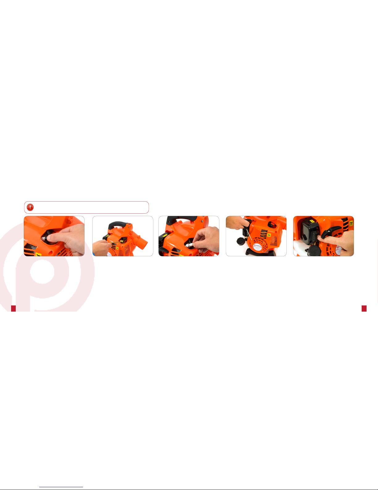
■CAUTION! Never use this machine if it has been damaged of is in need of replacement parts.
■Read this manual carefully before using this machine.
■Always use eye protection.
■Never operate this machine when you are fatigued, ill or under the inuence of alcohol, drugs or medication.
■Always wear heavy , long trousers, boots and gloves suitable for the job.
■Do not wear loose clothing, jewellery short trousers, sandles or use when barefoot, and secure long hair.
■Tighten the fuel cap to avoid spillage during vibration. Spilt fuel is a re risk.
■Never start or run the machine or engine inside a closed room or building, as fumes can kill.
■Stop the engine before installing or removing the machine tubes.
■Never perform maintenance or assembly procedures on this machine when the engine is running.
■Never direct the machine outlet towards people or animals.
■Use the machine at the lowest speed to do the job.
■Watch out for children, pets, open windows etc and blow debris safely away.
GENERAL SAFETY INSTRUCTIONS

5
4
PART DESCRIPTION
Intake pipe
C
Intake pipe
D
Fan cover Lower
handle
Dust bag
Discharge pipe
E
PIPE IDENTIFICATION
Blow pipe
A
Blow pipe
B
Intake pipe
C
Intake pipe
D
Discharge pipe
E

67
ASSEMBLING THE VACUUM
1. Open the fan cover, connect the intake pipe C and D.
2. Insert the discharge pipe into the dust bag
Discharge pipe
Use screw M5 x 10 to secure
ASSEMBLY

89
BLOWER ASSEMBLY
Stop switch
Throttle lever handle
Starter handle
Lower handle
Fuel tank
Air lter cover
(a) Fuel Tank (mixture of fuel and oil)
(b) Closed air position
(c) Open air position
THIS PAGE HAS INTENTIONALLY BEEN LEFT BLANK

10 11
BLOW PIPE INSTALL
NOTE: The pipe is a tight t to ensure that the vacuum is air tight!
1. Attach blow pipe B to the machine, rotate and screw to x.
2. Attach blow A to B by rotating.
Blow pipe A
Blow pipe B
Push, twist and turn
ASSEMBLY FILLING THE FUEL TANK
WARNING!
Danger of re and burn injury!
■Always use extreme care when handling petrol. It is highly
ammable.
■Never operate this blower if fuel system components are
damaged or are leaking.
■Never attempt to refuel a hot engine! Always allow the
blower engine to cool before refuelling!
■Don’t smoke or light any res near the blower or stored
fuel.
■Always transport and store after ensuring the exhaust.
■Only operate the blower after ensuring the exhaust is
functioning properly.
■Never operate the blower unless it is properly assembled
and in good working condition.
FILLING PROCEDURE
1. Stop the machine, and place on the ground or on a sturdy work
surface, and wipe any debris from around the fuel cap.
2. Remove the fuel cap.
Remove the
fuel ller cap

12 13
STEP 1: TURN THE ENGINE
SWITCH ‘ON’
Turn the engine swtich to the ‘ON’ position.
STEP 2: PRIME THE CARBURETOR
Prime the fuel system by repeatedly pressing
the fuel primer bulb at least 10 times.
STEP 3: FOR COLD ENGINE STARTS
For cold engine starts, make sure the engine
choke lever is closed (UP position) and for warm
starts the choke lever should be open (DOWN
position).
STARTING THE MACHINE
IMPORTANT!
For maximum vacuum performance and operating life, allow the engine to warm before use.
STEP 4: PULL THE STARTER
Place the machine on the ground, and hold the
handle rmly with your right hand. Pull the starter
cord slowly until you feel the resistance. Start
the machine by pulling the starter cord upward
rapidly. If necessary, repeat this step two or
three times until the engine starts.
STEP 5: RUN THE ENGINE
Run the engine at idle speed until operating
temperature is reached (2 to 3 minutes). As the
engine warms up, open the choke gradually
by slowly pushing the choke down to a ‘RUN’
position. The machine will now be ready for use.

14 15
STEP 1: DISCONNECT THE LEAD
Disconnect the spark plug lead.
STEP 2: REMOVE THE SPARK PLUG
Use the spark plug wrench to remove the plug
in a counter-clockwise direction. If the spark
plug is fouled or is soaked with fuel, clean or
replace the plug as required.
Clean excess fuel from the combustion
chamber by cranking the engine several times
while the spark plug is removed. Be sure to
have the ON/OFF switch in the OFF position.
STEP 3: INSTALL THE SPARK PLUG
Install the spark plug and rmly tighten up with
the spark plug wrench. If a torque wrench is
available, torque the spark plug to 148-165
inch-pounds. Reconnect the spark plug lead.
FLOODED ENGINE PROCEDURE
WARNING!
Incorrect spark plug installation can result in serious engine damage!
STEP 4: START THE ENGINE
Repeat the starting procedure for a “warm engine”.
STEP 5: RUN THE ENGINE
Run the engine at idle speed until operating
temperature is reached (2 to 3 minutes). As the
engine warms up, open the choke gradually
by slowly pushing the choke down to a ‘RUN’
position. The machine will now be ready for use.

16 17
ADJUSTING THE IDLE SPEED
ADJUSTING THE ENGINE IDLE SPEED
1. Start the engine by following the procedures described in the
preceding pages.
2. Run the engine at idle speed until operating temperature is
reached. This generally takes 2-3 minutes.
3. Use a screwdriver to adjust engine idle speed to 3000±200r/min.
■Turn the idle screw clockwise to increase engine
idle speed.
■Turn the idle screw counter-clockwise to decrease
Idle speed
adjusting screw
IMPORTANT!
Machine tubes and intake cover must
be installed while adjusting engine idle.
Engine idle speed will also be affected of
either the intake cover on machine tubes
are blocked, damaged or incorrectly
installed.
STOPPING THE ENGINE
1. Cool the engine by allowing it to run at idle for 2 or 3 minutes.
2. Stop the engine by pulling the stop switch.
c. Machine noise increases at higher throttle setting. Always
use the lowest throttle setting required to complete the job.
d. Never operate the blower when viability is poor.
e. Always wear eye protection such as a face shield or goggles
while operating this machine.
f. Wear a dust mask or reduce the risk of inhalation injuries.
g. Wear close-tting clothing to protect your legs and arms.
h. Wear hearing protection when operating this machine.
i. Never operate the blower of any component parts are
damaged, loose or missing.
STOPPING THE ENGINE
WARNING!
Never use the machine with any
pipes or guards removed.

18 19
ROUTINE MAINTENANCE
DAILY MAINTENANCE
■Remove dirt and debris from the blower exterior.
■Inspect the engine, tank and hose for possible fuel
leaks, and repair where needed.
■Inspect the engine cooling ns for build up of dirt
or debris, and clean as necessary.
■Inspect the entire machine for damage, loose or
missing components or
fastenings, and repair as necessary.
EVERY 10 HOURS
(More Frequently in dusty conditions)
1. Loosen the air cleaner cover retaining screw, and remove
the cover and lter element.
2. Inspect the lter. If the lter is distorted or damaged, replace
it with a new one.
3. Wash the lter in clean fuel or soap water, and squeeze or
blow dry. Wash the air cleaner cover in clean fuel, and wipe.
or blow dry.
4. Once dry, install the element and cover, and then tighten the
cover retaining screw.
EVERY 10/15 HOURS
1. Use the spark plug wrench to remove the plug (turn anti-
clockwise to remove).
2. Clean and adjust the spark plug gap to 0.6-0.7mm. Replace
any damaged or visibly worn plug with a champion RCJ6Y
or equivalent.
3. Install the spark plug nger-tight in the cylinder head, and
then tighten it rmly with the spark plug wrench. If a torque
wrench is available, torque the spark plug to 148-165 inch
pounds.
WARNING!
Before performing any maintenance
on this machine, stop the engine and
disconnect the spark plug cap.
EVERY 50 HOURS
(More Frequently in dusty conditions)
INSPECTION
Inspect the entire machine and tubes for damage, including loose or
missing components, and repair as necessary.
SPARK PLUG
Replace the spark plug with a champion RCK6Y, gapped to
(0.6-0.7)mm.
FUEL FILTER
Use a wire hook to extract the fuel lter from inside the fuel tank
and then remove and wash the lter element in clean fuel. Before
reinstalling the lter, inspect the condition of the fuel line. If damaged
or deterioration is noticed, the vacuum should be removed from
service until it can be inspected by a trained service technician.
STORAGE (30 days or longer)
CLEANING
Thoroughly clean the machine exterior
INSPECTION
Inspect the entire machine and tubes for damage, including loose or
missing components, and repair as necessary.
FUEL
Drain the fuel tank and then clear the carburettor and pipes by
running the machine until it runs dry of petrol.
LUBRICATION
Remove the spark plug, and then pour approximately 1/4-oz of oil
into the cylinder through the spark plug hole. Before reinstalling the
spark plug, pull the recoil starter 2 or 3 times to distribute the oil over
the cylinder walls.
AIR CLEANER
Remove, clean and reinstall the lter element.
CAUTION!
Never allow dirt or debris to enter the cylinder bore. Before removing the spark plug, thoroughly
clean the plug and cylinder head area. Allow the engine to cool before servicing the spark plug.
DO NOT tighten or loosen the spark plug while the engine is hot! Incorrect spark plug installation
can result in serious engine damage.

20 21
TROUBLESHOOTING
COMPRESSION
NORMAL
THE SPARK IS
CORRECT PROBABLE CAUSE CORRECTIVE ACTION
Yes Ye s
There is no fuel in the tank Add fuel to the tank
The fuel filter is dirty Clean the filter
There is water in the fuel Change the fuel
The fuel used is not appropriate Use fuel with an appropriate octane
level +100% synthetic oil
The safety switch of the ventilator
is loose or the cover is not closed
correctly
Tighten the safety switch
The carburetor is dirty Bring your machine to a
TIMBERPRO authorises dealer
Yes No
The switch is in the “OFF” position Put the switch in the “I” position
The spark plug is dirty Clean the spark plug
The spark plug wire is not connected Connect it
Loss of
connection Yes
The spark plug is loose Tighten it
Piston, parts of the piston, worn
cylinder
Bring your machine to a
TIMBERPRO authorises dealer
The cylinder is scratched Bring your machine to a
TIMBERPRO authorises dealer
The engine does
not turn Seized engine Bring your machine to a
TIMBERPRO authorises dealer
If the engine does not start:
SYMPTOM PROBABLY CAUSE CORRECTIVE ACTION
The engine slutters
Worn parts Bring your machine to a PARKER authorises
dealer
Worn piston Bring your machine to a PARKER authorises
dealer
Worn connector rod bearing Bring your machine to a PARKER authorises
dealer
The gear is worn Bring your machine to a PARKER authorises
dealer
The engine
overheats
Too much uninturrupted use Have 10 minute work breaks and let the
engine cool
Dirty exhaust pipe Bring your machine to a PARKER authorises
dealer
The fuel used is not appropriate Use fuel with an appropriate octane level
+100% synthetic oil
The engine has
trouble starting
Dirty carburetor Bring your machine to a PARKER authorises
dealer
Dirty air filter Clean the air filter
The fuel filter is stopped up Clean the fuel filter
The engine stops
and cannot stay idle Poorly regulated carburetor Bring your machine to a PARKER authorises
dealer
If the engine does not function correctly (lack of power, unstable, idle, etc.)

22 23
Description Leafblower Vac / Mulcher
Brand PARKER
Model PGBV - 2600
Displacement (cm3) 26
Power (w) 700
Engine speed (Km/h) 7.000
Capacity of the fuel tank(l) 0.5
Air speed (Km/h) 225
Air ow (m3/min) 10
Bag volumn (m3/min) 45
Average decibel level LwA, dB(A) (ISO 22868) (K=3,08dB(A)) 109
Average guaranteed decibel level LwA, dB(A) (ISO 22868) 112
Average level of sound pressure LwA, dB(A) (ISO 22868)(K=ZdB(A)) 95.7
Level of vibration of the main handle (ISO 22867) (K= yy m/s2) (m/s2) 9.72
Level of vibration of the secondary handle (ISO 22867) (K= yy m/s2) (m/s2) 16.10
Dry weight (kg) 4.5
SPECIFICATION
Description & Function:
Garden Leaf Blower
Model/Type:
PBV-2600
/ PGBV-2600
Manufacturing Date/Serial Number:
20157
Conforms to the following Directives:
☑ 2006/42/EC Machine Directive (MD)
☑ 2004/108/EC EMC Directive
☑ 2000/14/EC Noise Emissions Directive
☑ 97/68/EC NRMM Emissions Directive
and to the harmonised standard have been complied with:
☑ EN ISO 12100-2/A1:2009
☑ EN 15503:2009
Measured Sound Power Level (2000/14/EC) - LwA: 112dB(A)
Guaranteed Sounds Power Level - LwA: 105dB(A)
Maximum power (kW) = 0.70
Manufacturer’s authorised representative within the EC:
Parker Products Ltd.
Richmond Park
Richmond Road
Louth
LN11 0FU
Technical file complied by:
Parker Products Ltd.
Richmond Park
Richmond Road
Louth
LN11 0FU
Being the responsible person appointed by the manufacturer.
Signed:
Date: 01/01/17
Name: Jason Parker
Position: Managing Director
Company: Parker Products Ltd.

24 22
www.parkerbrand.co.uk
REVISION 2
PARKER
Table of contents
Other Parker Blower manuals

Parker
Parker Minuteman Hurricane Plus 5 User manual

Parker
Parker 947103-169cc Owner's manual

Parker
Parker Hurricane Plus Guide

Parker
Parker VAC-35 User manual

Parker
Parker PV-7705 User manual

Parker
Parker HT9608H Guide

Parker
Parker 947103 Owner's manual

Parker
Parker Hurricane Plus HT0805H Guide

Parker
Parker TIMBERPRO PBLB-6500 User manual