Parker 947103-169cc Owner's manual

Owner/Operator Manual
Manuel Du Propriétaire/Utilisateur
Blower
ENGLISH
FRANÇAIS
Gasoline containing up to 10% ethanol (E10) or up to 10% MTBE (methyl tertiary butyl ether) is
acceptable for use in this machine.
The use of any gasoline exceeding 10% ethanol (E10) or 10% MTBE will void the product warranty.
Il est possible d’utiliser de l’essence contenant jusqu’à 10% d’éthanol (E10) ou 10% de MTBE
(éther méthyl-tertiobutylique) sur cette machine.
L’utilisation d’une essence contenant plus de 10% d’éthanol (E10) ou de 10% de MTBE annulent la
garantie.
Models
947103 – 169cc Blower
947104 – 265cc Blower
947105 – 404cc Blower
04308100A 1/12
Printed in USA

GB - 2
SAFETY. . . . . . . . . . . . . . . . . . . . . . . . . . 4
ASSEMBLY . . . . . . . . . . . . . . . . . . . . . . . 7
CONTROLS AND FEATURES . . . . . . . . 9
OPERATION . . . . . . . . . . . . . . . . . . . . . 10
MAINTENANCE . . . . . . . . . . . . . . . . . . 13
STORAGE . . . . . . . . . . . . . . . . . . . . . . . 14
TROUBLESHOOTING . . . . . . . . . . . . . 15
SERVICE PARTS . . . . . . . . . . . . . . . . . 15
ACCESSORIES. . . . . . . . . . . . . . . . . . . 15
SPECIFICATIONS. . . . . . . . . . . . . . . . . 15
WARRANTY . . . . . . . . . . . . . . . . . . . . . 16
NON-ENGLISH MANUALS
Manuals in languages other than English may
be obtained from your Dealer. Visit your
dealer or www.parkersweeper.com for a list of
languages available for your equipment.
Manuals printed in languages other than
English are also available as a free download
on our website:
http://www.parkersweeper.com
MANUALES EN IDIOMAS
DIFERENTES DEL INGLES
Puede obtener manuales en idiomas
diferentes del inglés en su distribuidor. Visite
a su distribuidor o vaya a
www.parkersweeper.com para obtener una
lista de idiomas disponibles para su equipo.
También puede imprimir manuales en
idiomas diferentes del inglés descargándolos
gratuitamente de nuestra página Web:
http://www.parkersweeper.com
MANUELS NON ANGLAIS
Des manuels dans différentes langues sont
disponibles chez votre revendeur. Rendez-
vous chez votre revendeur ou allez sur le site
www.parkersweeper.com pour consulter la
liste des langues disponibles pour votre
équipement.
Les manuels imprimés dans des langues
différentes de l'anglais sont également
disponibles en téléchargement gratuit sur
notre site Web:
http://www.parkersweeper.com
MANUALS
Before operation of unit, carefully and
completely read your manuals. If used
improperly, this unit could be dangerous and
cause personal injury or property damage.
The contents will provide you with safety
instructions for the safe use of your unit
during normal operation and maintenance.
All reference to left, right, front, or rear are
given from operator standing in operation
position and facing the direction of forward
travel.
ENGINE MANUAL
The engine on this unit is covered by a
separate manual specific to the engine. This
manual is included in the literature package
that shipped with the unit. Refer to this
manual for engine service recommendations.
If the engine manual is not available, contact
the engine manufacturer for a replacement
manual.
MODEL AND SERIAL NUMBERS
When ordering replacement parts or making
service inquiries, know the Model and Serial
numbers of your unit and engine.
Numbers are located on the product
registration form in the unit literature
package. They are printed on a serial number
label, located on the frame of your unit.
TABLE OF CONTENTS
INTRODUCTION
WARNING: AVOID INJURY. Read
and understand the entire Safety
section before proceeding.

GB - 3
• Record Unit Model and Serial
numbers here.
• Record Engine Model and Serial
numbers here.
PRODUCT REGISTRATION
The dealer must register the product at the
time of purchase. Registering the product will
help the company process warranty claims or
contact you with the latest service
information. All claims meeting requirements
during the limited warranty period will be
honored, whether or not the product
registration card is returned. Keep a proof of
purchase if you do not register your unit.
Customer Note: If the dealer does not
register your product, please fill out, sign, and
return the product registration card to Parker
or go to www.parkersweeper.com.
UNAUTHORIZED REPLACEMENT
PARTS
Use only Parker replacement parts. The
replacement of any part on this vehicle with
anything other than a Parker authorized
replacement part may adversely affect the
performance, durability, or safety of this unit
and may void the warranty. Parkerdisclaims
liability for any claims or damages, whether
warranty, property damage, personal injury or
death arising out of the use of unauthorized
replacement parts. To locate your nearest
Parker Dealer, go to
www.parkersweeper.com on the internet.
DISCLAIMER
Parker reserves the right to discontinue,
make changes to, and add improvements
upon its products at any time without public
notice or obligation. The descriptions and
specifications contained in this manual were
in effect at printing. Equipment described
within this manual may be optional. Some
illustrations may not be applicable to your
unit.
DELIVERY
Customer Note: If you have purchased this
product without complete assembly and
instruction by your retailer, it is your
responsibility to:
1. Read and understand all assembly
instructions in this manual. If you do not
understand or have difficulty following
the instructions, contact your nearest
Parker Dealer for assistance. Make sure
all assembly has been properly
completed.
NOTE: To locate your nearest Parker Dealer,
go to www.parkersweeper.com on the
Internet.
2. Understand all Safety Precautions
provided in the manuals.
3. Review control functions and operation
of the unit. Do not operate the unit
unless all controls function as described
in this manual.
4. Review recommended lubrication,
maintenance and adjustments.
5. Review Limited Warranty Policy.
NOTE: This machine comes with a one-year
limited warranty. The selling dealer is
responsible for explaining the terms and
limitations of the warranty coverage offered in
the country of sale.
6. Fill out a Product Registration Card and
return the card to Parker or go to
www.parkersweeper.com.
Figure 1
Serial
Number
Label
WARNING: Improper assembly or
adjustments can cause serious
injury.

GB - 4
SAFETY ALERTS
Look for these symbols to point
outimportantsafetyprecautions.
They mean:
Attention!
Personal Safety Is
Involved!
Become Alert!
Obey The Message!
The safety alert symbols above and signal
words below are used on decals and in this
manual. Read and understand all safety
messages.
NOTATIONS
NOTE: General reference information for
proper operation and maintenance practices.
IMPORTANT: Specific procedures or
information required to prevent damage to
unit or attachment.
PRACTICES AND LAWS
Practice usual and customary safe working
precautions, for the benefit of yourself and
others. Understand and follow all safety
messages. Be alert to unsafe conditions and
the possibility of minor, moderate, or serious
injury or death. Learn applicable rules and
laws in your area. Always follow the practices
set forth in this manual.
REQUIRED OPERATOR
TRAINING
Original purchaser of this unit was instructed
by the seller on safe and proper operation. If
unit is to be used by someone other than
original purchaser; loaned, rented or sold,
ALWAYS provide this manual and any
needed safety training before operation.
SAFETY DECALS AND
LOCATIONS
ALWAYS replace missing or damaged Safety
Decals. Refer to figure below for Safety Decal
locations.
SAFETY
WARNING: This machine is capable
of amputating hands and feet and
throwing objects. Failure to observe
the safety instructions in the manuals
and on decals could result in serious
injury or death.
Slopes are a major factor related to
slip and fall accidents. Operation on
all slopes requires extra caution.
Tragic accidents can occur if the
operator is not alert to the presence
of children. Never assume that
children will remain where you last
saw them.
Gasoline is extremely flammable and
the vapors are explosive, handle with
care.
Stop unit and engine and allow
moving parts to stop before leaving
operator’s position.
DANGER: IMMINENTLY
HAZARDOUS SITUATION! If not
avoided, WILL RESULT in death or
serious injury.
WARNING: POTENTIALLY
HAZARDOUS SITUATION! If not
avoided, COULD RESULT in death or
serious injury.
CAUTION: POTENTIALLY
HAZARDOUS SITUATION! If not
avoided, MAY RESULT in minor or
moderate injury. It may also be used
to alert against unsafe practices.

GB - 5
1. DANGER! TO AVOID SERIOUS
INJURY OR DEATH EMISSION CONTROL SYSTEM
This equipment and/or its engine may include
exhaust and evaporative emissions control
system components required to meet U.S.
Environmental Protection Agency (EPA)
and/or California Air Resources Board
(CARB) regulations. Tampering with emission
controls and components by unauthorized
personnel may result in severe fines or
penalties. Emission controls and components
can only be adjusted by an Ariens Company
dealer or an authorized engine
manufacturer's service center. Contact your
Ariens Company Equipment Retailer
concerning emission controls and component
questions.
SAFETY RULES OPERATION
To prevent personal injury or property
damage, do not attempt to start engine until
all assembly steps are complete and you
have read and understand the safety and
operating instructions in this manual.
If unit is to be used by someone other than
original purchaser; loaned, rented or sold,
ALWAYS provide this manual and any
needed safety training before operation.
If the operator or the mechanic cannot read
the manual, it is the owner’s responsibility to
explain it to them. Only the user can prevent
and is responsible for accidents or injuries
occurring to themselves, other people or
property.
07700030
Figure 2
Keep safety devices (guards,
shields, switches, etc.) in place
and working.
Read Operator’s Manual.
Wear hearing protection.
AVOID INJURY. Stay clear of
rotating parts.
Keep children and others away
from unit while operating.
Never direct discharge toward
other people. Thrown objects
can cause injury.
OL1801
OL4690
OL3270
OL4370
OL0910

GB - 6
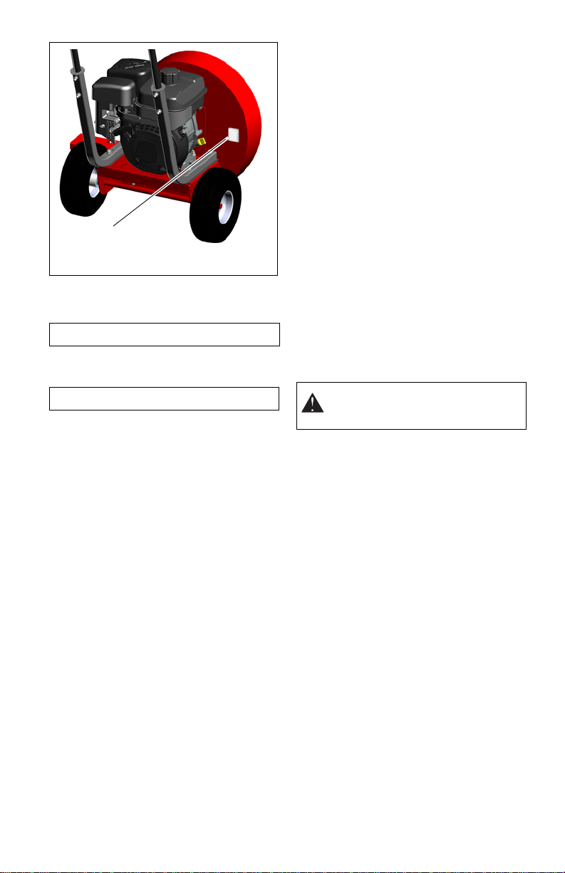
This product is equipped with an internal
combustion engine. DO NOT use on or near
any unimproved, forest or brush covered land
unless the exhaust system is equipped with a
spark arrestor meeting applicable local, state
or federal laws. A spark arrestor, if used,
must be maintained in effective working order
by the operator.
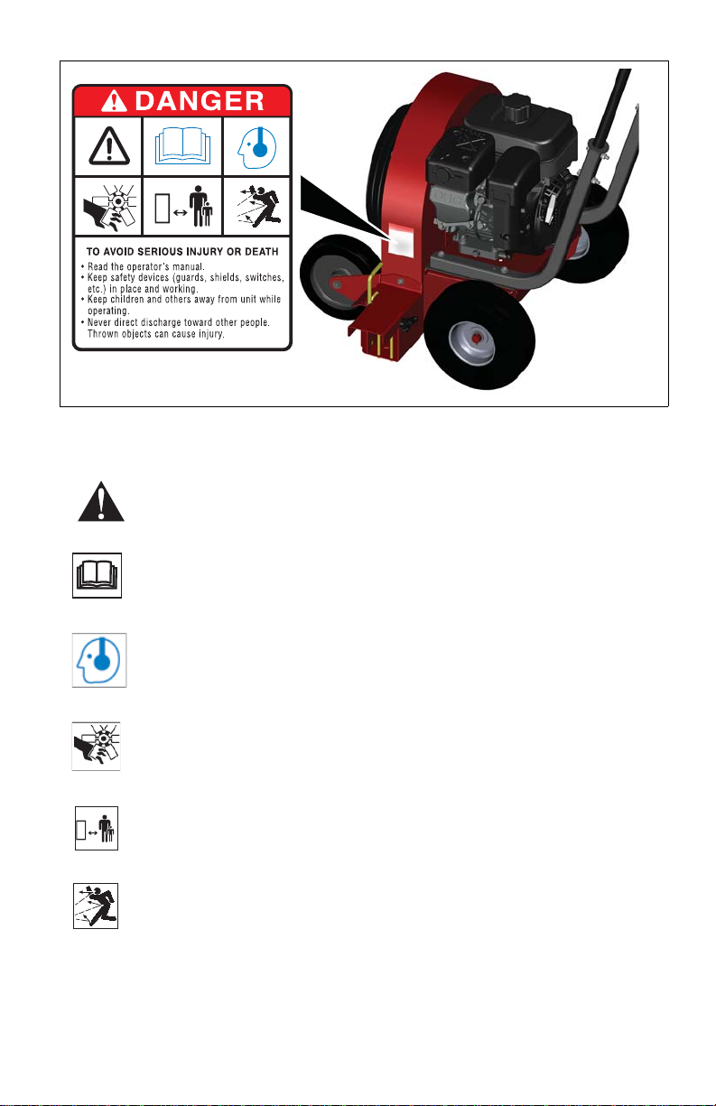
Wear approved safety glasses when
operating this equipment. The operation of
any powered machine can result in foreign
objects being thrown by high-speed rotating
parts.
Wear work gloves, sturdy footwear, and
hearing protection when operating this
equipment.
Remove hearing protection and watch for
traffic when operating near, or when crossing
roadways.
Before inspecting or servicing any part of
equipment, shut off engine, disconnect spark
plug wire from spark plug, and make sure that
all moving parts have come to a complete
stop. Be aware that rotating blades slow
down gradually after engine is shut off.
Never leave equipment unattended when
engine is running. Shut off engine and
disconnect spark plug wire from spark plug
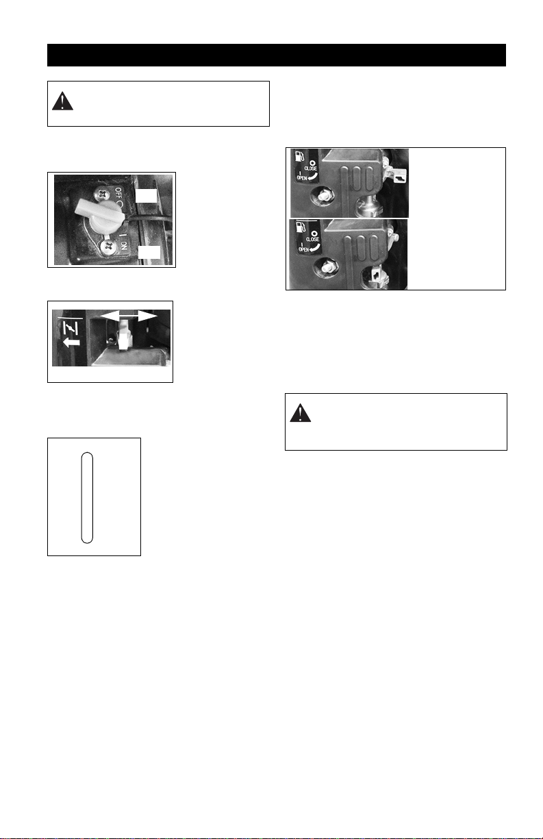
before leaving equipment. Close the fuel
shut-off valve.
Exercise extreme caution on slopes and
avoid excessively steep slopes.
Use extreme caution when moving backward
or pulling the machine towards you.
Do not change the engine governor or over
run the engine.
Do not tilt the equipment when starting the
engine or switching on the motor.
Do not start the engine when standing in front
of the air discharge outlet.
Walk, never run.
ALWAYS be sure of your footing. Use caution
to avoid slipping and falling.
Operate machine only in daylight or good
artificial light.
NEVER operate after or during the use of
medication, drugs or alcohol. Unit requires
complete and unimpaired attention.
If the machine should start to vibrate
abnormally, stop the engine (motor) and
check for the cause immediately. Vibration is
generally a warning of trouble.
Do not weld or repair damaged or worn
impeller. Replace only.
Never allow children or untrained adults to
operate this equipment.
Keep the area of operation clear of all
persons, particularly small children, and pets.
Keep bystanders at least 25 feet away from
the area of operation.
Do not run engine in an enclosed area.
Engine exhaust contains carbon monoxide
gas, a deadly poison that is odorless,
colorless, and tasteless.
Before making air flow adjustments, shut off
engine, and allow all moving parts to come to
a complete stop.
Do not move through or stand in the air flow
with the engine running. Blown debris can
cause injury.
Do not allow hands or any other part of the
body or clothing inside the air intake or
discharge areas.
Do not start engine or operate this equipment
with any safety guards removed.
See manufacturer’s instructions for proper
operation and installation of accessories.
Only use accessories approved by the
manufacturer.
Fuel is highly flammable and its vapors are
explosive. Handle with care. Use only an
approved gasoline container with an
appropriately sized dispensing spout.
Fuel is highly flammable and its vapors can
explode. ONLY use approved fuel containers.
•NOSmoking!
•NOSparks!
•NOFlames!
• Allow engine to cool before filling fuel
tank.
Never fill containers inside a vehicle or on a
truck or trailer bed with a plastic liner. Always
place containers on the ground away from
your vehicle before filling.
When practical, remove gas-powered
equipment from the truck or trailer and refuel
it on the ground. If this is not possible, then
refuel such equipment on a trailer with a
portable container, rather than from a
gasoline dispenser nozzle.
Keep the nozzle in contact with the rim of the
fuel tank or container opening at all times until
fueling is complete. Do not use a nozzle lock-
open device.
Check fuel supply before starting engine.
DO NOT fill gasoline tank indoors, when
engine is running, or while engine is hot.
Allow engine to cool several minutes before
removing fuel cap.
Do not mix oil with gasoline.
DO NOT overfill. Allow about 1/2” (12 mm) of
tank space for fuel expansion.

GB - 7
Replace gasoline tank cap securely and
clean any spilled fuel before starting engine.
If fuel is spilled on clothing, change clothing
immediately.
Properly remove fuel before tipping unit.
NEVER store fuel inside where there is an
open flame, such as a water heater.
ALWAYS drain fuel outdoors away from
ignition sources.
Never pick up or carry equipment while the
engine is running.
ALWAYS shut off engine and close fuel
shutoff valve when transporting unit on a
truck or trailer.
Use at least two people when loading or
unloading machine.
DO NOT drop machine when loading or
unloading or damage to rear axle may occur.
The blower covered in this owner's guide is
shipped complete in one box. Follow all
instructions on assembly very carefully.
Carton Contents
Unit
Literature Pack
ASSEMBLY
1. Remove all items from carton.
2. Position blower on its wheels and chock
wheels to keep unit stable.
NOTE: DO NOT discard the carton or any of
the inserts until the unit is completely
assembled.
3. Remove four 5/16" hex bolts (item 4),
four 5/16" locking hex nuts (item 2) and
handlebar brackets (item 5) that are
loosely assembled on the handlebar
supports.
Handle Assembly
(Figure 3)
1. Mount handlebar (item 1) to the
handlebar supports (item 3) using four
5/16" hex bolts, four 5/16" locking hex
nuts and two handlebar brackets.
2. Torque fasteners to 17 lbf-ft (1.9 N•m).
Do not overtighten.
ASSEMBLY
WARNING: AVOID INJURY. Read
and understand the entire Safety
section before proceeding.
Figure 3
1
1. Handlebar
2. 5/16" Locking Hex Nut
3. Handlebar Support
4. 5/16" Hex Bolt
5. Handlebar Bracket
2
3
4
5

GB - 8
Attach Throttle Lever Assembly
(Figure 4)
1. Locate the hex bolt (item 2) and locking
nut (item 3) in the literature package.
2. Route the throttle cable up to the right
side of the handlebar.
3. Attach the throttle lever assembly (item
1) to the outside of the handlebar using
the hex bolt and locking hex nut.
4. Torque fasteners to 8 lbf-ft (.9 N•m). Do
not overtighten.
Check Engine Oil
Refer to the engine manual for recommended
viscosity and amount.
Fill Fuel Tank
Fill fuel tank. DO NOT OVERFILL! See
FILLING FUEL TANK on page 12.
Check Tire Pressure
See SPECIFICATIONS on page 15.
WARNING: Check engine oil and add
if necessary. Read the Engine
Instruction Manual carefully before
operating the unit. Be sure you know
how to start and stop the engine
before proceeding further. Do not
start the engine until all assembly is
finished.
WARNING: Make a thorough
inspection to see that all fasteners are
tight and all parts are properly
installed.
Figure 4
1. Throttle Lever Assembly
2. Hex Bolt
3. Locking Nut
1
3
2
CAUTION: Avoid injury!
Explosive separation of tire and
rim parts is possible when they
are serviced incorrectly:
• Do not attempt to mount a
tire without the proper
equipment and experience
to perform the job.
• Do not inflate the tires
above the recommended
pressure.
• Do not weld or heat a
wheel and tire assembly.
Heat can cause an
increase in air pressure
resulting in an explosion.
Welding can structurally
weaken or deform the
wheel.
• Do not stand in front or
over the tire assembly
when inflating. Use a clip-
on chuck and extension
hose long enough to allow
you to stand to one side.

GB - 9
1. Throttle Lever
2. Remote Throttle Lever
3. Recoil Starter
4. Fuel Tank and Cap
5. Choke Lever
6. Fuel Shut-off Valve
7. Oil Fill/Dipstick
8. Muffler
9. Air Cleaner
10. Direction Control Lever
11. Horizontal Air Flow Deflector
12. Horizontal Deflector Lock Knob
13. Engine Switch
CONTROLS AND FEATURES
Figure 5
12
11
7
3
10
4
2
1
6
8
9
13
5

GB - 10
ENGINE
Engine Switch The engine
switch has two
positions:
1. OFF – Engine
will not start or
run.
2. ON – Engine
will start and run.
Choke Control Lever 1.Choke Closed
position: chokes
off air to engine
for easier start.
2.Choke Open
position: allows
for normal
operation.
IMPORTANT: Gradually open choke after
engine starts.
Throttle Control Lever
The throttle controls the
engine speed. To
increase or decrease
the engine speed,
adjust to:
1. Fast (Normal or
Warm Starts)
2. Part-Throttle
3. Slow (Cold Weather
Starts)
Fuel Shut-Off Valve
IMPORTANT:The fuel shut-off valve MUST
be in the closed position prior to
transporting the unit.
The fuel shut-off valve has two positions:
Recoil Starter Handle
When pulled, handle will turn engine over.
IMPORTANT: DO NOT let handle snap back
against starter.
USING THE BLOWER
Air flow can be directed to the front or to the
side of the unit using the direction control
lever.
• The front discharge position is used to
move debris away from walls, curbs,
fences, etc. This position pushes the
debris to the front of the unit.
• The side discharge position moves
debris to the side and is used to form
piles or rows of debris.
The horizontal air flow deflector is used to
force airflow down to allow it to penetrate
under heavier or wet debris
OPERATION
WARNING: AVOID INJURY. Read
and understand the entire Safety
section before proceeding.
1
2
2
1
1
3
2
FAST
SLOW
WARNING: AVOID INJURY! Do not
move through or stand in the air flow
with the engine running. Blown debris
can cause injury.
Open Position:
Use this position
to run the unit.
Closed Position:
Use this position
to service,
transport, or
store the unit.

GB - 11
Direction Control Lever
(Figure 6)
For side air flow:
1. Lift the direction control lever (item 3) up,
move to the forward position and
release.
2. Ensure that the assembly locks securely
into the front notch on the bottom of the
outlet.
3. Adjust the horizontal air deflector for the
desired air flow angle and tighten.
For forward air flow:
1. Lift the direction control lever (item 3) up,
move to the rear position and release.
2. Ensure that the assembly locks securely
into the rear notch on the bottom of the
outlet.
3. Move the horizon al air deflector to the
down position to allow unit to operate
closely to walls, fences, etc.
WARNING: AVOID INJURY! Stop the
engine and wait for the impeller
blades to stop rotating before making
any adjustments to the air flow.
Impeller blades will continue to rotate
for a short time after the engine has
been shut off.
Figure 6
Air Flow to the Front
Air Flow to the Side
1. Horizontal Air Deflector Up
2. Horizontal Air Deflector Down
3. Direction Control Lever
4. Vertical Air Deflector Rear Position
5. Vertical Air Deflector Forward Position
1
2
4
5
3
3

GB - 12
Horizontal Air Flow Deflector
(Figure 7)
Loosen the knob on the rear of the discharge
opening and move the deflector to the
desired position. Tighten the knob to hold the
deflector in position.
Positioning the air flow deflector at a
downward angle will force the air flow down
at a greater angle allowing it to more easily
work under heavier or wet debris.
NOTE: Ensure that the Direction control lever
is in the correct position for side air flow.
BEFORE STARTING ENGINE
IMPORTANT: Read the Engine Manual
CAREFULLY before operating the unit.
Before starting the engine:
1. Be sure the engine crankcase is filled
with the proper type and amount of oil.
2. Make sure that the air flow will be
directed away from bystanders, pets,
buildings, etc. once the engine starts.
FILLING FUEL TANK
To add fuel to the fuel tank:
1. Clean fuel cap and surrounding area to
prevent dust, dirt, and debris from
entering fuel tank.
2. Remove fuel cap.
IMPORTANT: Refer to Engine Manual for
correct type and grade of fuel.
3. Fill fuel tank to the bottom of filler neck.
See SPECIFICATIONS on page 15 for
fuel tank capacity.
IMPORTANT: DO NOT OVERFILL! This
equipment and/or its engine may include
evaporative emissions control system
components, required to meet EPA and/or
CARB regulations, that will only function
properly when the fuel tank has been filled to
the recommended level. Overfilling may
cause permanent damage to evaporative
emissions control system components. Filling
to the recommended level ensures a vapor
gap required to allow for fuel expansion. Pay
close attention while filling the fuel tank to
ensure that the recommended fuel level
inside the tank is not exceeded. Use a
portable gasoline container with an
appropriately sized dispensing spout when
filling the tank. Do not use a funnel or other
device that obstructs the view of the tank
filling process.
4. Replace fuel cap and tighten.
5. ALWAYS clean up spilled fuel.
Start Engine
1. Move fuel shutoff valve to the open
position.
2. Move engine switch to ON position.
3. Open the throttle about halfway and
close the choke if engine is cold. A warm
engine may require little or no choke to
start.
4. Slowly pull the recoil starter until engine
compression makes pulling difficult. Let
the starter rewind a little, and then pull
smoothly and quickly to start the engine.
5. Repeat step 4as needed.
6. When engine starts gradually open the
choke until fully opened. Do not fully
open the choke immediately when the
engine is cold or the ambient
temperature is low which could cause
the engine to stall.
7. Gradually move the throttle lever toward
the high speed position and set it at the
desired engine speed for amount of air
flow required.
Stop Engine
1. Move throttle lever to slow position until
engine idles.
2. Move engine switch to the OFF position.
3. Remove any hearing protection and
listen for all moving parts to come to a
complete stop.
4. Move the fuel shutoff valve to the closed
position.
WARNING: AVOID INJURY! Stop the
engine and wait for the impeller
blades to stop rotating before making
any adjustments to the air flow.
Impeller blades will continue to rotate
for a short time after the engine has
been shut off.
Figure 7
1. Horizontal Air Deflector
2. Knob
1
2
1

GB - 13
GASOLINE
IMPORTANT: ALWAYS use gasoline that
meets the following guidelines:
• Clean, fresh gasoline.
• A minimum of 87 octane/87 AKI (91
RON). High altitude use may require a
different octane. Consult your engine
manual.
• Gasoline with up to 10% ethanol
(gasohol) or up to 10% MTBE (methyl
tertiary butyl ether) is acceptable.
• Use of any gasoline other than those
approved above will void the engine
warranty. If the pumps are not marked
for the content of alcohol or ethers,
check ethanol and MTBE levels with
the fuel supplier.
• Do not modify the fuel system to use
different fuels.
• Never mix oil and gasoline.
NOTE: All gasoline is not the same. If the
engine experiences starting or performance
problems after using a new gasoline, switch
to a different fuel provider or fuel brand.
IMPORTANT: Excessively oxygenated or
reformulated fuels (fuels blended with
alcohols or ethers) can damage the fuel
system or cause performance problems. If
any undesirable operating problems occur,
use a gasoline with a lower percentage of
alcohol or ether.
LUBRICATION
Add a few drops of oil to the throttle control
cable and wire to help keep it operating
smoothly.
IMPELLER REMOVAL
(Figure 8)
1. Remove the locking hex nuts (item 1)
and remove intake grille (item 2). Retain
hardware.
NOTE: Model 947103 has four intake grille
mounting points. Models 947104 and 947105
have eight mounting points.
2. Remove hex bolt (item 3) and flat
washer (item 4) retaining the impeller
assembly. Discard hardware.
3. Loosen two set screws located on side
of fan hub.
MAINTENANCE
WARNING: AVOID INJURY. Read
and understand the entire Safety
section before proceeding.
Interval Task Action
Each Use Check Tires See SPECIFICATIONS on page 15 for correct tire pressure.
Clean Unit Clean engine, blower housing, etc. of dirt and debris. Do not
use solvents, hard cleaners, or abrasives.
NOTE: Protect painted surfaces with automotive type wax.
Follow Engine
Maintenance
Schedule
Perform scheduled engine maintenance. Refer to Engine
Manual for detailed instructions.
Every 8
Hours Check
Fasteners Inspect for loose hardware or excessive vibration.
Every 150
Hours Inspect impeller. Check to ensure that there are no cracks or damage to the
impeller housing or the impeller.
Figure 8
1. 5/16" Locking Hex Nut
2. Intake Grille
3. Impeller Bolt
4. Flat Washer
12
3
4

GB - 14
4. Thread a 5/8-11 hex bolt into the nut on
the end of the impeller shaft. Tighten bolt
until the impeller is forced loose of the
shaft.
NOTE: Heating the impeller fan up to 250
degrees F will aid in removing fan.
5. Remove and inspect the impeller for
cracks, deterioration or damage.
Replace if necessary. DO NOT repair.
Installation
1. Apply recommended amount of Red
Loctite®262 or equivalent locking
compound to impeller mounting bolt.
2. Apply Loctite®609 to keyway groove in
engine shaft.
3. Ensure that key on engine output shaft is
in position and aligned with slot in
impeller. Apply additional adhesive to
top of key and both sides of crankshaft
next to key.
NOTE: Ensure adhesive spreads down onto
remainder of crankshaft before installing
impeller.
4. Install impeller with impeller mounting
and replace hardware.
5. Tighten set screws on fan hub.
6. Tighten impeller retaining bolt and
torque to the specification shown in the
chart:
7. Install intake grille and tighten locking
hex nuts to 17 lbf-ft (23 N•m).
IMPORTANT: NEVER spray unit with high-
pressure water or store unit outdoors. Store
unit in a cool, dry, protected location.
Cleaning
NOTE: Allow unit to cool before cleaning.
Clean unit thoroughly with forced air or mild
soap and low pressure water. Brush off dirt
and debris from all surfaces. Touch up all
scratched surfaces to prevent rust. Matching
touch-up paint is available from your Dealer.
Do not use abrasives, solvents, or harsh
cleaners.
Inspection
Inspect unit and repair or replace worn or
damaged parts to avoid delays when
beginning use again.
Regularly check all hardware and keep
fasteners tight. Know unit is in safe working
condition.
Fuel System
Gasoline left in the fuel system for extended
periods without a stabilizer will deteriorate,
resulting in gum deposits in the system.
These deposits can damage the carburetor
and the fuel hoses, filter and tank. Prevent
deposits from forming in the fuel system
during storage by adding a quality fuel
stabilizer to the fuel. Follow the
recommended mix ratio found on the fuel
stabilizer container.
To treat the fuel system for storage:
1. Add fuel stabilizer according to
manufacturer’s instructions.
2. Run engine for at least 10 minutes after
adding stabilizer to allow it to reach the
carburetor.
NEVER store the engine with fuel in the fuel
tank inside of a building with potential
sources of ignition.
WARNING: AVOID DAMAGE.
Applying excessive heat to impeller
fan will damage the engine oil seals.
Figure 9
1. 5/8-11 Hex Nut
1
Impeller Mounting Bolt Torque
Model Bolt Torque
947103 5/16-24 x 2"
Gr. 8 14.8 – 16.2 lbf-ft
(20 – 22 N•m)
947104 7/16-20 x 2"
Gr. 5 36.9 – 44.3 lbf-ft
(50 – 60 N•m)
947105 3/8-24 x 1.75"
Gr. 8 33.2 – 40.6 lbf-ft
(45 – 55 N•m)
STORAGE
CAUTION: AVOID INJURY. Read
and understand the entire Safety
section before proceeding.

GB - 15
TROUBLESHOOTING
PROBLEM PROBABLE CAUSE CORRECTION
Engine will not
start. 1. No gas in the fuel tank.
2. Fuel shut-off valve closed.
3. Engine switch is in the
OFF position.
4. Build up of dirt and
residue around
governor/carburetor.
1. Fill tank with clean, fresh gasoline.
Fill fuel tank (see FILLING FUEL
TANK on page 12).
2. Open fuel shut-off valve.
3. Turn the engine switch to ON
position.
4. Clean area around
governor/carburetor.
Engine runs briefly
and stops. 1. Fuel shut-off valve closed.
2. Contaminated fuel supply. 1. Open fuel shut-off valve.
2. Replace with clean fuel.
SERVICE PARTS
Order the following parts through your
Dealer:
Part No. Qty Description
20020001 AR Spark Plug
20020002 AR Air Filter (947103)
21547300 AR Air Filter (947104)
21550200 AR Air Filter (947105)
ACCESSORIES
Order the following accessories through
your Dealer:
Part No. Description
74700300 Hose Kit – Small (947103)
74700200 Hose Kit – Medium (947104)
74700400 Swivel Caster Kit
SPECIFICATIONS
Model Number 947103 947104 947105
Description Walk-Behind Blower
Engine Subaru
Engine Model SP170 (CARB) EX27 (CARB) EX40
Displacement – Cu. In. (cc) 10.31 (169) 16.2 (265) 24.7 (404)
Oil Capacity – Fl. Oz. (ml) 20.3 (600) 33.8 (1000) 32 (946)
Starting Recoil
Fuel Type Unleaded Gasoline
Fuel Capacity – US Gal. (l) .95 (3.6) 1.59 (6.0) 1.85 (7.0)
Dimensions
Length
–
in (cm) 47.76 (121.3) 48.6 (123.4) 49.5 (125.7)
Height
–
in (cm) 41 (104)
Width
–
in (cm) 27.16 (69) 30.66 (77.9) 33 (83.8)
Weight
–
lb (kg) 124 (56.2) 157 (71.2) 205 (93)
Wheel Dia. – in (cm) Front 8 (20.3) 9 (22.9)
Tire Inflation – Max. psi (kpa) Front N/A 50 (344.7)
Wheel Dia. – in (cm) Rear 10
Tire Inflation – Max. psi (kpa) Rear 24 (165.5)

Sno-Chore_2012
16
Sno-Thro®, Sno-Tek®and
Chore Performing Equipment
Limited Warranty
Ariens Company (Ariens) warrants to the original purchaser that Ariens, Gravely, Parker, and Countax
brand chore performing equipment (including Sno-Thro®and Sno-Tek®equipment) purchased on or after
1/1/2011 will be free from defects in material and workmanship for the time period noted in the chart below.
Equipment put to personal use around a single household or residence is considered “Consumer Use”;
equipment put to any business use (agricultural, commercial, or industrial) or used at multiple locations is
considered “Commercial Use.” If any product is rented or leased, then the duration of these warranties shall
be 90 days after the date of purchase.
An authorized Ariens dealer (Ariens brand products), Gravely dealer (Gravely brand products), Parker dealer
(Parker brand products), or Countax dealer (Countax brand products) will repair any defect in material or
workmanship, and repair or replace any defective part, subject to the conditions, limitations and exclusions
set forth herein. Such repair or replacement will be free of charge (labor and parts) to the original purchaser
except as noted below.
Special Extensions
The chart below details special extensions to this warranty:
Warranty
Code Product Group Warranty Period
Consumer Use Warranty Period
Commercial Use
PA Log Splitters, Brushes, String Trimmers, Edgers 3 Years 90 Days
PB Professional Powered Brushes 3 Years 1 Year
PC Tillers 2 Years 90 Days
PD Vacuums, Blowers, Sweepers, Truck Loaders,
Lawn Rakes, Sprayers, Aerators, etc. 1 Year 1 Year
SA Professional Sno-Thro®3 Years 1 Year
SB Compact, Deluxe, Platinum, AMP™ Sno-Thro®3 Years 90 Days
SC Sno-Tek®2 Years 90 Days
UA Utility Vehicles 1 Year 1 Year
N/A Service (Replacement) Parts 90 Days (no labor) 90 Days (no labor)
Warranty
Code Warranty Exception Warranty
Period Use Detail
SA Cast Iron Auger
Gear Case 5 Years All 5 Years for all users including
Commercial
SB Cast Iron Auger
Gear Case 5 Years Consumer 5 Years for Consumer use;
1 Year for Commercial Use
SB Batteries for AMP™
Sno-Thro®2 Years Consumer 100% first year; prorated second year.

Sno-Chore_2012
17
Exceptions and Limitations
The chart below details special exceptions to this warranty:
Customer Responsibilities
Register the product immediately at the time of sale. If the dealer does not register the product, the
customer must complete the product registration card in the literature package and return it to the Ariens
Company, or register the unit online at www.ariens.com, www.gravely.com, www.countax.com,
www.parkersweeper.com.
To obtain warranty service, the original purchaser must:
• Perform the maintenance and adjustments explained in the owner's manual.
• Promptly notify Ariens or an authorized Ariens, Gravely, Parker or Countax service representative of
the need for warranty service.
• Transport the product to and from the place of warranty service at owner's expense.
• Have the warranty service performed by an authorized Ariens, Gravely, Parker or Countax service
representative.
To Find an Authorized Service Representative:
Warranty
Code Warranty Exception Warranty
Period Use Detail
All Batteries 1 Year All Prorated
All Belts, Muffler, Tires None Commercial These components are not covered
when used commercially.
All Cloth, Plastic, and
Rubber Components
(Including Belts and
Cables)
Maximum
2 Years All
Warranty is limited to 2 years for
consumer use. (1 year for warranty
code "PD".) Except as noted above,
these components are covered for
defect, not for wear.
SA, SB,
SC Idlers Maximum
2 Years All Warranty is limited on idlers to
2 years for consumer use.
All Engines See Engine
Manufacturer’s
Warranty All Engines are covered by engine
manufacturer’s warranty. Refer to
engine manufacturer’s warranty
statement.
In the U.S. and Canada:
Use the dealer locator on our websites: www.ariens.com • www.gravely.com
Or contact us by mail or by phone:
In the U.S., Canada, Mexico, Caribbean,
Central and South America: In Europe, Asia, Africa or
the Middle East: In Australia or New Zealand:
Ariens Company
655 W. Ryan Street
Brillion, WI 54110
Phone: (920) 756 - 4688
www.ariens.com
Countax Ltd, Countax House
Great Haseley, Oxfordshire,
OX44 7PF
Phone: 0800 597 7777
www.countax.com
109-111 Abbot House
Hallam, Victoria 3803 Australia
Phone: (03) 9796 4244
1800 335 489
www.bynorm.com.au

Sno-Chore_2012
18
Exclusions - Items Not Covered by This Warranty
• Parts that are not genuine Ariens, Gravely, Parker or Countax service parts are not covered by this
warranty and may void the warranty.
• Damages resulting from the installation or use of any part, accessory, or attachment which is not
approved by the Ariens Company for use with product(s) identified herein are not covered by this
warranty.
• The following maintenance, service and replacement items are not covered by this warranty unless
they are noted in the Limitations section above: lubricants, spark plugs, oil, oil filters, air filters, fuel
filters, brake linings, brake arms, brake shoes, skid shoes, scraper blades, shear bolts, mower
blades, mower vanes, brushes, headlights, light bulbs, knives, cutters.
• Any misuse, alteration, improper assembly, improper adjustment, neglect, or accident which
requires repair is not covered by this warranty.
• Use of gasoline blends exceeding 10% ethanol voids any and all warranties.
• Products are designed to the specifications in the area that the product was originally distributed.
Different areas may have significantly different legal and design requirements. This warranty is lim-
ited to the requirements in the area in which the unit was originally distributed. Ariens Company
does not warrant this product to the requirements of any other area. Warranty service is limited to
service within the area originally distributed.
• In countries other than the United States and Canada, contact the Ariens Company dealer for war-
ranty policies that govern within your country. Rights may vary from country to country and within
any one country.
Special Exclusions on Utility Vehicles
The following uses void the warranty terms on Utility Vehicles (Warranty Code UA):
• Renting or leasing the utility vehicle.
• Using the utility vehicle to tow or carry loads in excess of the limits specified in the owner/operator
manual.
• Modifying the utility vehicle with parts and accessories that are not genuine or authorized Ariens or
Gravely parts or accessories.
• Modifying the utility vehicle without express written authorization from the Ariens Company.
• Operating the utility vehicle when it has not been completely and properly assembled and
pre-delivered by an authorized Gravely dealer.
Disclaimer
Ariens Company may from time to time change the design of its products. Nothing contained in this warranty
shall be construed as obligating the Ariens Company to incorporate such design changes into previously
manufactured products, nor shall such changes be construed as an admission that previous designs were
defective.
LIMITATION OF REMEDY AND DAMAGES
Ariens Company's liability under this warranty, and under any implied warranty that may exist, is limited to
repair of any defect in workmanship, and repair or replacement of any defective part. Ariens Company shall
not be liable for incidental, special, or consequential damages (including lost profits). Some states do not
allow the exclusion of incidental or consequential damages, so the above limitation or exclusion may not
apply to you.
AUSTRALIAN CONSUMER LAW
The following applies solely to warranties subject to Subsection 102(1) of the Australian Consumer Law: Our
goods come with guarantees that cannot be excluded by the Australian Consumer Law. You are entitled to a
replacement or refund for a major failure and for compensation for any other reasonably foreseeable loss or
damage. You are also entitled to have the goods repaired or replaced if the goods fail to be of acceptable
quality and failure does not amount to a major failure.
DISCLAIMER OF FURTHER WARRANTY
Ariens Company makes no warranty, express or implied, other than what is expressly made in this
warranty. If the law of your state provides that an implied warranty of merchantability, or an implied
warranty of fitness for particular purpose, or any other implied warranty, applies to Ariens Company,
then any such implied warranty is limited to the duration of this warranty. Some states do not allow
limitations on how long an implied warranty lasts, so the above limitation may not apply to you.
This warranty gives you specific legal rights, and you may also have other rights which vary from region to region.

CARB/EPA 2012
19
CALIFORNIA AND EPA (UNITED STATES ENVIRONMENTAL
PROTECTION AGENCY) EVAPORATIVE EMISSION CONTROL
WARRANTY STATEMENT
YOUR WARRANTY RIGHTS AND OBLIGATIONS
The CARB (California Air Resources Board), the EPA, and Ariens Company are pleased to explain the
evaporative emission control system's warranty on your 2012 model year small off-road equipment. In
California, new equipment that uses small off-road engines must be designed, built, and equipped to
meet the State's stringent anti-smog standards. Ariens Company must warrant the evaporative
emission control system on your small off-road equipment for the period listed below provided there
has been no abuse, neglect or improper maintenance of your equipment.
Your evaporative emission control system may include parts such as: fuel tanks, fuel lines, fuel caps,
valves, canisters, filters, vapor hoses, clamps, connectors, and other associated components.
MANUFACTURER'S WARRANTY COVERAGE:
This evaporative emission control system is warranted for two years. If any evaporative
emission-related part on your equipment is defective, the part will be repaired or replaced by Ariens
Company.
OWNER'S WARRANTY RESPONSIBILITIES:
• As the small off-road equipment owner, you are responsible for the performance of the required
maintenance listed in your Owner's Manual. Ariens Company recommends that you retain all
receipts covering maintenance on your small off-road equipment, but Ariens Company cannot deny
warranty solely for the lack of receipts.
• As the small off-road equipment owner, you should however be aware that the Ariens Company may
deny you warranty coverage if your evaporative emission control system part has failed due to
abuse, neglect, or improper maintenance or unapproved modifications.
• You are responsible for presenting your small off-road equipment to an authorized Ariens, Gravely,
or Parker service representative as soon as the problem exists. The warranty repairs should be
completed in a reasonable amount of time, not to exceed 30 days. If you have a question regarding
your warranty coverage, you should contact Ariens Company Technical Service Center at
1-920-756-2141.
DEFECTS WARRANTY REQUIREMENTS:
(a.) The warranty period begins on the date the small off-road equipment is delivered to an ultimate
purchaser.
(b.) General Evaporative Emissions Warranty Coverage. Ariens Company warrants to the ultimate
purchaser and any subsequent owner that the evaporative emission control system when
installed was:
(1.) Designed, built, and equipped so as to conform with all applicable EPA and CARB
regulations; and
(2.) Free from defects in materials and workmanship that causes the failure of a warranted part
for a period of two years.
(c.) The warranty on evaporative emissions-related parts will be interpreted as follows:
(1.) Any warranted part that is not scheduled for replacement as required maintenance in the
written instructions must be warranted for the warranty period defined in subsection (b)(2).
If any such part fails during the period of warranty coverage, it must be repaired or replaced
by the Ariens Company. Any such part repaired or replaced under the warranty must be
warranted for a time not less than the remaining warranty period.
(2.) Any warranted part that is scheduled only for regular inspection in the written instructions
must be warranted for the warranty period defined in subsection (b)(2). A statement in such
written instructions to the effect of "repair or replace as necessary" will not reduce the
period of warranty coverage. Any such part repaired or replaced under warranty must be
warranted for a time not less than the remaining warranty period.
(3.) Any warranted part that is scheduled for replacement as required maintenance in the
written instructions must be warranted for the period of time prior to the first scheduled
replacement point for that part. If the part fails prior to the first scheduled replacement, the
part must be repaired or replaced by the Ariens Company. Any such part repaired or
replaced under warranty must be warranted for a time not less than the remainder of the
period prior to the first scheduled replacement point for the part.

CARB/EPA 2012
20
(4.) Repair or replacement of any warranted part under the warranty provisions of this article
must be performed at no charge to the owner at an authorized Ariens, Gravely, or Parker
service representative.
(5.) Notwithstanding the provisions of subsection (4) above, warranty services or repairs must
be provided at authorized Ariens, Gravely, or Parker service representatives that are
franchised to service the subject small off-road equipment.
(6.) The owner must not be charged for diagnostic labor that leads to the determination that a
warranted part is in fact defective, provided that such diagnostic work is performed at an
authorized Ariens, Gravely, or Parker service representative.
(7.) Throughout the evaporative emission control system's warranty period set out in subsection
(b)(2), the Ariens Company must maintain a supply of warranted parts sufficient to meet the
expected demand for such parts.
(8.) Manufacturer-approved replacement parts must be used in the performance of any
warranty maintenance or repairs and must be provided without charge to the owner. Such
use will not reduce the warranty obligations of the manufacturer issuing the warranty.
(9.) The use of any add-on or modified parts will be grounds for disallowing a warranty claim
made in accordance with this article. The manufacturer issuing the warranty will not be
liable under this Article to warrant failures of warranted parts caused by the use of an
add-on or modified part.
Evaporative Emission Warranty Parts List
The following parts are considered emission-related components for evaporative emissions:
• Fuel Tank, Fuel Cap and Tether
• Fuel Line, Fuel Line Fittings, Clamps*
• Pressure Relief Valves, Control Valves*
• Control Solenoids*, Electronic Controls*
• Vacuum Control Diaphragms*
• Control Cables*, Control Linkages*
• Purge Valves
• Vapor Hoses, Liquid/Vapor Separator
• Carbon Canister, Canister Mounting Brackets
• Carburetor Purge Port Connector
* As related to the evaporative emission control system
Disclaimer
New equipment sold in the state of California that uses small off-road engines must be exclusively
certified and appropriately labeled for sale in California. Some equipment covered by this Owner's
Manual my not be certified for sale in California and the presence of the preceding CARB and EPA
Warranty Statement does not by its existence indicate which, if any, of the equipment covered by this
Owner's Manual may be sold in California.
Some equipment covered by this Owner's Manual may have been manufactured prior to certain
affectivity dates requiring the inclusion of evaporative emission control systems. Therefore some
equipment covered by this Owner's Manual may not include the evaporative emission control systems
referred to in the preceding CARB and EPA Warranty Statement.
This manual suits for next models
5
Table of contents
Other Parker Blower manuals

Parker
Parker VAC-35 User manual

Parker
Parker HT9608H Guide

Parker
Parker PGBV-2600 User manual

Parker
Parker 947103 Owner's manual

Parker
Parker TIMBERPRO PBLB-6500 User manual

Parker
Parker Hurricane Plus Guide

Parker
Parker Hurricane Plus HT0805H Guide

Parker
Parker Minuteman Hurricane Plus 5 User manual

Parker
Parker PV-7705 User manual
Popular Blower manuals by other brands

Hitachi Koki
Hitachi Koki Tanaka THB-260PF Handling instructions

Makita
Makita PM7650H Owner's and safety manual

AirTech
AirTech ASC 1M Series Installation and operating instruction

Robin
Robin FL231 instruction manual

Tanaka
Tanaka TBL7800/7800R owner's manual

Masport
Masport Energy Flex LBV 4090 owner's manual