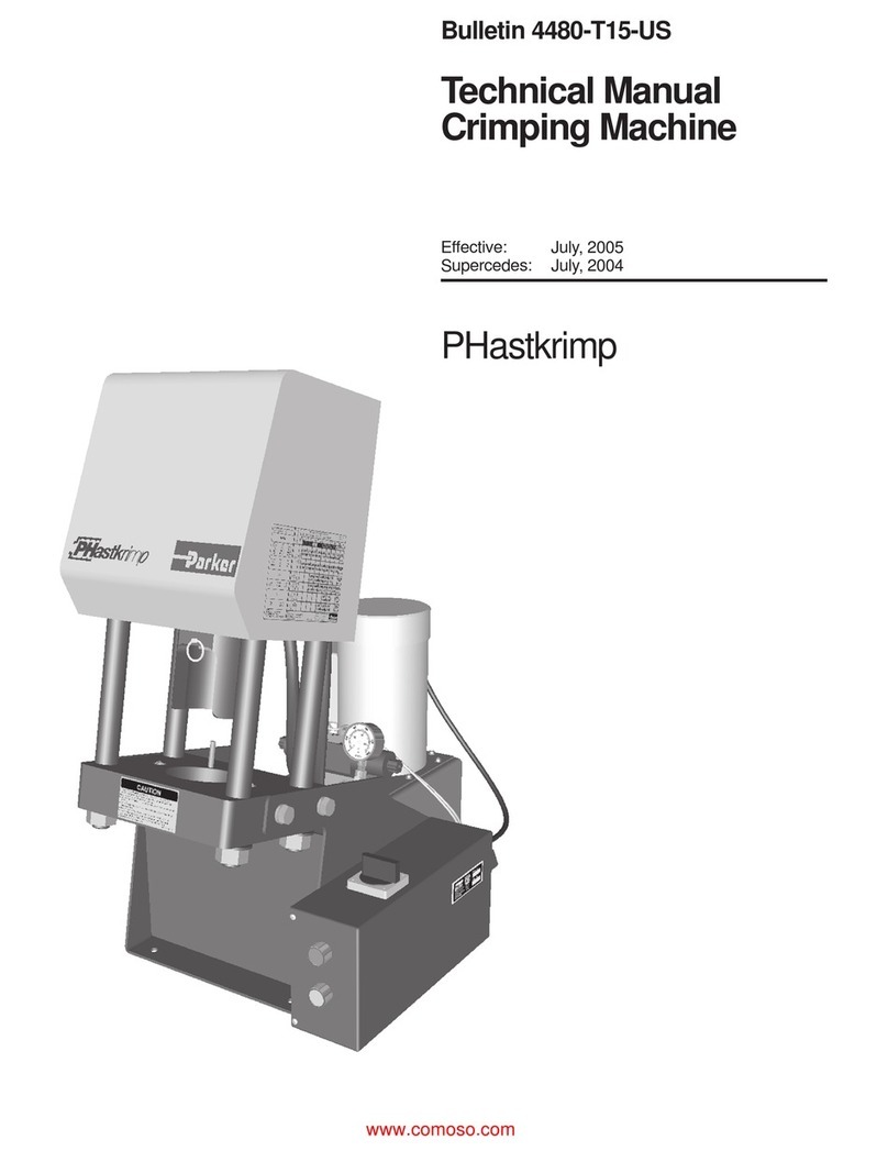
Parker Parkrimp 2 - 83CE-083U User manual

Maintenance
6-2
6.1 Daily maintenance
Maintenance objects Actions (to be performed by operator)
Figure 6-2 Plant
Perform a visual inspection of the plant
for
cleanliness
leaks
outside damage
Figure 6-3 Crimping tool
Perform a visual inspection of the crimping tool
for
cleanliness
proper condition
Figure 6-4 Level indicator
Check the hydraulic oil level on the level indi-
cator.
The oil level is in the centre.
Remove oil, dirt dust and chips using a vacu-
um cleaner.
Construction and Function
3-4
3.2.1 Assembly instructions
Figure 3-7 Rear die ring half
Move cylinder and pusher fully up.
Push rear die ring half up and lock it using a pin.
Figure 3-8 Adapter element
Insert adapter element into die holder. Tilt it slight-
ly and position correctly.
Figure 3-9 Die set
Insert die set into lubricated tool holder ensuring
that the individual segments are distributed even-
ly. The die sets are colour-coded according to
hose size.
Construction andConstruction and Function
3-3
Figure 3-5 Front crimp ring half mounted
Figure 3-6 Control panel
1 Lift pusher
2 Lower pusher
Move the pusher up (lift pusher).
Remove the front crimp ring half.
Remove the workpiece from the tool (safety dis-
tance 120 mm minimum).
Check the correct seat of the fitting and the cor-
rect dimension.
2
1
Parkrimp®2 – 83CE-083U
Instruction Manual
Instruction Manual
Hose Crimper Machine Parkrimp2 83CE-083U

Bulletin 4480-T12/UK
Hose Crimper Machine Parkrimp®2
Imprint
Translation of the original instruction manual
Hose Crimper Machine Parkrimp2 83CE-083U
Manufacturer:
Uniflex-Hydraulik GmbH
Robert-Bosch-Straße 50-52
D-61184 Karben
Deutschland
Phone: +49 (0) 60 39 / 91 71 - 0
Fax: +49 (0) 60 39 / 91 71 41
Art. no.: 83CE-083U
As of: September 2010
Version: 1.0
Revision: 0.0
Copyright 2010 by Uniflex-Hydraulik GmbH
Subject to alteration without notice
Imprint

Hose Crimper Machine Parkrimp®2
Bulletin 4480-T12/UK
Contents
Chapter Page
1 Introduction, Designated Use ........................................................................................ 1-1
1.1 Fundamentals ................................................................................................................... 1-1
1.2 Target groups.................................................................................................................... 1-2
1.3 Designated use ................................................................................................................. 1-2
2 Safe Operation, Pollution Control.................................................................................. 2-0
2.1 General remarks ............................................................................................................... 2-0
2.2 Definition of terms ............................................................................................................. 2-1
2.3 Operational safety instructions..........................................................................................2-3
2.3.1 Safety signs at the site ..................................................................................................... 2-3
2.3.2 Recommended working area ...........................................................................................2-3
2.3.3 Noise emissions ............................................................................................................... 2-4
2.4 To be observed ................................................................................................................. 2-5
2.4.1 Prior to switching-on or restoring of power....................................................................... 2-5
2.4.2 During operation............................................................................................................... 2-5
2.4.3 In case of maintenance and repair ................................................................................... 2-7
2.5 Emergency measures .......................................................................................................2-8
2.6 Operating and waste materials.......................................................................................... 2-8
3 Construction and Function ............................................................................................ 3-1
3.1 Construction ...................................................................................................................... 3-1
3.2 Function ............................................................................................................................ 3-2
3.2.1 Assembly instructions....................................................................................................... 3-4
4 Transport, Dimensions, Installation, Intermediate Storage ........................................ 4-0
4.1 Transport........................................................................................................................... 4-0
4.1.1 Weights ............................................................................................................................ 4-0
4.2 Dimensions ....................................................................................................................... 4-0
4.3 Installation ......................................................................................................................... 4-1
4.3.1 Structural requirements .................................................................................................... 4-1
4.3.2 Energy required................................................................................................................ 4-1
4.3.3 Ambient conditions ........................................................................................................... 4-1
4.4 Intermediate storage of the plant....................................................................................... 4-2
4.5 Installation ......................................................................................................................... 4-2
5 Operation ......................................................................................................................... 5-1
5.1 First commissioning .......................................................................................................... 5-1
5.2 Switching-on...................................................................................................................... 5-2
5.3 Switching-off...................................................................................................................... 5-2
5.4 Restoring of power ............................................................................................................ 5-2
5.5 Operating mode ................................................................................................................ 5-3
5.6 Emergency stop ................................................................................................................ 5-4
Contents

Bulletin 4480-T12/UK
Hose Crimper Machine Parkrimp®2
Contents
6 Maintenance.....................................................................................................................6-1
6.1 Daily maintenance .............................................................................................................6-2
6.2 Monthly maintenance ........................................................................................................6-4
6.3 Yearly maintenance...........................................................................................................6-5
7 Spare Parts List ...............................................................................................................7-0
8 Declaration of Conformity ..............................................................................................8-1
Contents

Hose Crimper Machine Parkrimp®2
Bulletin 4480-T12/UK
Introduction, Designated Usenated Use
1-1
1 Introduction, Designated Use
1.1 Fundamentals
In this Instruction Manual the “Hose Crimper Machine Parkrimp2 83CE –
083U“ is always designated as plant.
This instruction manual contains important information on how to oper-
ate your plant
safely
properly and
most efficiently.
Observing these instructions helps
to reduce dangers
to minimise repair costs and downtimes and
to increase the reliability and service life of the plant.
The plant has been designed in accordance with state-of-the-art stand-
ards.
Using the plant contrary to its designated use may, however, constitute a
risk to life and limb of the user or cause damage to the plant.
Therefore use the plant only
in technically perfect condition
within the limits of its designated use
with safety-consciousness and fully aware of the risks involved and
in accordance with all instructions set out in this instruction manual
This instruction manual contains the rules and regulations for the desig-
nated use of your plant. Only if these rules and regulations are observed
the plant is operated according to its designated use. Any risk of opera-
tion contrary to its designated use lies entirely with the user.
Read this instruction manual before
switching the plant on
switching the plant off
servicing or
repairing the plant
Only staff
who have read this instruction manual, which must always be ready
at hand, and
understood the instructions and
have been fully instructed
are authorized to operate the machine.
Introduction, Designated Usenated Use
1-1

Bulletin 4480-T12/UK
Hose Crimper Machine Parkrimp®2
Introduction, Designated Usenated Use
1-2
1.2 Target groups
This instruction manual is intended for the following target groups:
the user
the operator
1.3 Designated use
This plant is intended for industrial use, suitable only for crimping
Parker hydraulic hose lines of
size 4 (DN 6) to size 32 (DN 50).
Use exclusively Parker fittings.
Use exclusively colour-coded Parkrimp die sets with 8 segments.
The hydraulic hose lines, the fittings and the die sets must be
tuned to each other.
Machining takes place in single strokes. The workpieces are load-
ed and unloaded manually.
The maximum hydraulic pressure is 280 bar.
Do not make any changes to the design of the plant.
The operating temperature is between 10oC and 40oC.
The plant must be operated in closed premises.
Operation in hazardous locations is prohibited.
Any other use is considered contrary to its designated use.
The consequences of any misuse lie exclusively with the user.
Please note:
Operating the plant within the limits of its designated use involves also
observing the prescribed
instructions for switching-on
instructions for switching-off
operating instructions
maintenance and servicing measures and
disposal procedures
Only staff who have read and understood the – always accessible – in-
struction manual, and who have signed it in the appendix and who have
been fully instructed are authorized to operate the machine.
Any person entrusted with the maintenance of or work on the plant must
have read and understood the corresponding parts of this instruction
Introduction, Designated Usenated Use
1-2

Hose Crimper Machine Parkrimp®2
Bulletin 4480-T12/UK
Introduction, Designated Usenated Use
1-3
manual and in particular the chapter 2, “Safe Operation, Pollution Con-
trol“.
The user of the plant must inform the personnel about possible risks
which may occur.
National regulations apply without restriction.
The user must be sure that the instruction manual has been understood.
A copy of the instruction manual must always be available at the place of
use of the plant in a place intended for this purpose.
Introduction, Designated Usenated Use
1-3

Bulletin 4480-T12/UK
Hose Crimper Machine Parkrimp®2
Safe Operation, Pollution Control
2-0
2 Safe Operation, Pollution Control
2.1 General remarks
The plant has been built in accordance with state-of-the-art standards.
This plant may constitute a risk if it is used incorrectly or not in accord-
ance with its designated use.
The instruction manual serves for operating the plant in accordance with
its designated use and for safety-conscious working on the plant.
Any person entrusted with work on the plant must have read and under-
stood the operating instructions and in particular this chapter “Safe Op-
eration, Pollution Control“.
Safety instructions serve industrial safety and accident prevention and
must always be observed.
Therefore keep this instruction manual always in a place on the plant in-
tended for this purpose so that it is always at hand at the place of use of
the plant.
Your co-operation is vital to protect yourself and your colleagues from in-
jury.
Set to work with circumspection always being aware of the fact that risks
are mostly not "obvious“.
The plant has been built in accordance with state-of-the-art standards.
This plant may constitute a risk if it is used incorrectly or not in accord-
ance with its designated use.
Safety devices serve your health. They must always be fully functional
and must never be modified
The instruction manual serves for operating the plant in accordance with
its designated use and for safety-conscious working on the plant.
Any person entrusted with work on the plant must have read and under-
stood the operating instructions and in particular this chapter “Safe Op-
eration, Pollution Control“.
Safety instructions serve industrial safety and accident prevention and
must always be observed.
Therefore keep this instruction manual always in a place on the plant in-
tended for this purpose so that it is always at hand at the place of use of
the plant.
Your co-operation is vital to protect yourself and your colleagues from in-
jury.
Set to work with circumspection always being aware of the fact that risks
are mostly not "obvious“.
The following symbols are intended to draw your attention to instructions
of particular importance in this manual.
The following symbols are intended to draw your attention to instructions
of particular importance in this manual.
2-0

Hose Crimper Machine Parkrimp®2
Bulletin 4480-T12/UK
Safe Operation, Pollution Control
2-1
DANGER This symbol stands next to all safety in-
structions in this manual where danger
to life and limb may occur. Always ob-
serve these instructions and proceed
with special caution in these situations.
All other persons entrusted with work on
the machine must be informed of all
safety instructions. In addition to the in-
structions in this manual the general
safety and accident prevention regula-
tions must be observed.
ATTENTION This symbol stands at points in this in-
struction manual of particular im-
portance for compliance with regulations
and directives, for correct work flow and
for the prevention of damage to and de-
struction of the plant.
CRUSHING
HAZARD
This symbol stands at points in this in-
struction manual where a crushing haz-
ard to your hands may occur.
SHEARING
HAZARD
This symbol stands at points in this in-
struction manual where a shearing haz-
ard to your hands may occur.
IMPORTANT Special information in the instruction
manual on how to use the plant most ef-
ficiently.
Working steps or operations to be car-
ried out in the order stated.
General specifications.
Table 3-1 Symbols and their signification
2.2 Definition of terms
Residual hazards
Residual hazards are non-obvious risks which result from the use of the
plant. Although the plant has been developed, designed and built in ac-
cordance with state-of-the-art standards and the generally accepted
technical guidelines and regulations, residual hazards cannot entirely be
excluded – not even during designated use.
Safe Operation, Pollution Control
2-1

Bulletin 4480-T12/UK
Hose Crimper Machine Parkrimp®2
Safe Operation, Pollution Control
2-2
User
The user is any natural person or legal entity that utilises the plant for it-
self or on whose behalf it is utilised. The user may appoint a representa-
tive to exercise all rights and to perform all duties of the user by proxy.
Supervisor
A supervisor is a person appointed by the user to train and instruct the
operator in the correct operation of the plant in accordance with the des-
ignated use. In addition, the supervisor has to ensure that maintenance
and servicing work and regular inspections are carried out, unless differ-
ent provisions have been made.
Competent and qualified personnel
Competent and qualified personnel are persons who, by reason of their
special training and experience, possess adequate knowledge in a spe-
cial field and who are familiar with the relevant industrial safety and ac-
cident prevention regulations together with the generally acknowledged
technical guidelines and regulations.
Instructed personnel
Instructed personnel are persons who have been instructed, and where
necessary trained, by a qualified person in the particular tasks entrusted
to them, who have been informed about possible risks resulting from im-
proper behaviour and about the necessary safety devices and protective
measures.
Operator
The operator is a person commissioned by the user, or any other ap-
pointed person who holds the power to do so, to operate the plant in ac-
cordance with its designated use.
Setter
Setters of hydraulic presses must be at least 18 years old and trained for
the job, i.e. must have taken part in a specific training.
Protective clothing
Protective clothing is a personal protective equipment intended to pro-
tect the body against residual hazards resulting from the work process. It
is the user's responsibility to ensure that the personal protective equip-
ment used complies with the legal regulations for appliance safety.
The relevant accident prevention regulations applicable to the work or
workplace concerned specify in detail when personal protective equip-
ment must be used.
Safe Operation, Pollution Control
2-2

Hose Crimper Machine Parkrimp®2
Bulletin 4480-T12/UK
Safe Operation, Pollution Control
2-3
2.3 Operational safety instructions
2.3.1 Safety signs at the site
2.3.2 Recommended working area
Keep the working area clear of obstacles.
Install lines and cables in ducts, if possible.
Provide for adequate lighting at the workplace.
Provide for free access to the hydraulic supply system.
There is one workplace at the plant covering the following working area:
Figure 2-1 Working area
Workplace for manual operation
Safe Operation, Pollution Control
2-3

Bulletin 4480-T12/UK
Hose Crimper Machine Parkrimp®2
Safe Operation, Pollution Control
2-4
2.3.3 Noise emissions
The sound level meter according to IEC 804, class 2, was calibrated pri-
or to measuring.
During operation of the plant noise emissions of Leq = 73.7 dBA occur at
the workplace. No noise protection measures are necessary.
Date Time=10/06/18 08:41:00
Sampling Time=1
Record Num= 17
Leq Value=73.7; SEL Value=85.8
MAX Value=83.7; MIN Value=68.2
Freq Weighting=A; Time Weighting=Fast
76.7,08:41:00,
69.6,08:41:01,
70.5,08:41:02,
69.7,08:41:03,
69.6,08:41:04,
69.9,08:41:05,
70.1,08:41:06,
68.7,08:41:07,
70.2,08:41:08,
69.0,08:41:09,
71.7,08:41:10,
75.6,08:41:11,
74.2,08:41:12,
74.0,08:41:13,
75.2,08:41:14,
75.8,08:41:15,
72.4,08:41:16,
In connection with other machines higher noise emissions
may occur at the workplace. In this case the plant user must
provide for suitable protective measures, e.g.
prescribe ear protections
information/briefing on the hazards
marking of the hazardous area
medical checks
Safe Operation, Pollution Control
2-4

Hose Crimper Machine Parkrimp®2
Bulletin 4480-T12/UK
Safe Operation, Pollution Control
2-5
2.4 To be observed
2.4.1 Prior to switching-on or restoring of power
Provide for sufficient lighting in the working area of the plant.
The operating personnel must be informed about the location and opera-
tion of the fire alarm and fire fighting equipment.
This equipment must be freely accessible.
Suitable tools are attached to the plant.
Perform
switching-on,
switching-off or
restoring of power
always according to this instruction manual.
2.4.2 During operation
Production
Observe the safety instructions on the plant.
Crimpers are dangerous machines – they can easily
cut off parts of your body – always be aware of this risk during
work.
To protect your hands always observe the safety dis-
tance of 120 mm minimum to the crimping tool.
Safe Operation, Pollution Control
2-5

Bulletin 4480-T12/UK
Hose Crimper Machine Parkrimp®2
Safe Operation, Pollution Control
2-6
Figure 2-2 Safety distance 120 mm minimum
Check each gesture (motor activity) with your eyes (sensory func-
tion). Controlled movements must always be monitored by the sen-
sory system.
Ensure that no other person is in the working area.
Do not eat, drink and smoke at the workplace.
End of work
Switch off the plant on the main switch.
Thoroughly clean your hands after the end of work.
Safe Operation, Pollution Control
2-6

Hose Crimper Machine Parkrimp®2
Bulletin 4480-T12/UK
Safe Operation, Pollution Control
2-7
2.4.3 In case of maintenance and repair
Work on the hydraulic system
The plant is equipped with a hydraulic station including a pump and a
motor.
Any maintenance and repair work on the hydraulic station of
the plant or any components may only be carried out by expert staff of
UNIFLEX-HYDRAULIK GmbH!
Welding, cutting and grinding work
Welding work
cutting work and
grinding work
on and in the plant or in its surroundings require express permission –
there is risk of fire.
Even if the work is permitted, the plant must be cleaned from dust and
combustible materials.
Sufficient ventilation must be ensured.
Safe Operation, Pollution Control
2-7

Bulletin 4480-T12/UK
Hose Crimper Machine Parkrimp®2
Safe Operation, Pollution Control
2-8
2.5 Emergency measures
In case of emergency immediately switch off the plant on the main
switch.
Figure 2-3 Main switch
Before restarting the plant remove the cause of the emergency
stop.
2.6 Operating and waste materials
It is the plant user’s duty to follow the pollution control and waste
removal regulations applying to his company and his region.
It is the plant user’s duty to disclose necessary legal regulations to
the operating personnel, and inform about necessary amendments
resulting from the function of the plant.
It is the plant user’s duty to point to the improper use of operating
and waste materials.
Ensure that appropriate measures are taken in the event of acci-
dents and fires.
Return hydraulic oil to the supplier – because it is hazardous
waste.
Safe Operation, Pollution Control
2-8

Hose Crimper Machine Parkrimp®2
Bulletin 4480-T12/UK
Construction andConstruction and Function
3-1
3 Construction and Function
3.1 Construction
Figure 3-1 Construction of the plant
1 Guard hood
2 Pusher
3 Control panel
4 Main switch
5 Housing
6 Internal hydraulic pump
7 Electric motor with internal hydraulic pump
1
4
2
7
3
6
5
Construction and Function
3-1

Bulletin 4480-T12/UK
Hose Crimper Machine Parkrimp®2
Construction and Function
3-2
3.2 Function
Figure 3-2 Safety distance 120 mm minimum
Figure 3-3 Adapter cone and die set
Figure 3-4 Eyelet ring and rear crimp ring half
Crimpers are dangerous machines
– they can easily cut off parts of your body –
always be aware of this risk during work.
Always check the movements of your hands
with your eyes when loading and unloading the
workpieces – to ensure that you only perform
controlled movements.
To protect your hands always ob-
serve the safety distance of 120 mm minimum
to the crimping tool.
The minimum requirements for cor-
rect crimping include:
Fitting and tool have been tuned to each
other.
The correct spacer ring, the correct adapter
cone and the correct die set have been
mounted.
Mark the hose insertion depth on the hose.
Push the hose into the fitting up to the
marked insertion depth.
Put a preassembled workpiece into the tool
from the bottom (safety distance of your
hands 120 mm minimum).
Unlock the rear crimp ring half using the
eyelet ring.
Mount the front crimp ring half.
Position the workpiece in the tool (safety
distance 120 mm minimum).
Start the crimping cycle (pusher down) on
the control panel and lower the pusher to
the stop.
Construction and Function
3-2

Hose Crimper Machine Parkrimp®2
Bulletin 4480-T12/UK
Construction andConstruction and Function
3-3
Figure 3-5 Front crimp ring half mounted
Figure 3-6 Control panel
1 Lift pusher
2 Lower pusher
Move the pusher up (lift pusher).
Remove the front crimp ring half.
Remove the workpiece from the tool (safety dis-
tance 120 mm minimum).
Check the correct seat of the fitting and the cor-
rect dimension.
2
1
Construction and Function
3-3

Bulletin 4480-T12/UK
Hose Crimper Machine Parkrimp®2
Construction and Function
3-4
3.2.1 Assembly instructions
Figure 3-7 Rear die ring half
Move cylinder and pusher fully up.
Push rear die ring half up and lock it using a pin.
Figure 3-8 Adapter element
Insert adapter element into die holder. Tilt it slight-
ly and position correctly.
Figure 3-9 Die set
Insert die set into lubricated tool holder ensuring
that the individual segments are distributed even-
ly. The die sets are colour-coded according to
hose size.
Construction and Function
3-4
Table of contents
Other Parker Crimping Tools manuals