Parker Hannifin Corporation
Hose Products Division
Wickliffe, OH
8
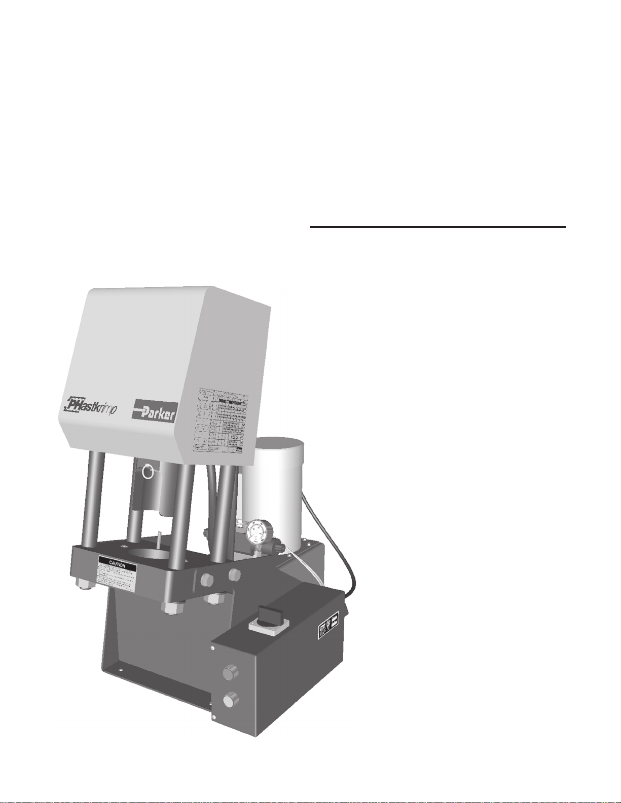
Crimping Machine
PHastkrimp
Bulletin 4480-T15-US
The following crimping dies are available for use with the PHastkrimp machine:
73 & 78 Series Fittings Dies (Olive Drab)
80C-L12 Size -12 (3/4") Color Coded Green
80C-L16 Size -16 (1") Color Coded Black
26 Series Fitting Dies (Silver)
80C-E04 Size -4 (3/16") Color Coded Red
80C-E05 Size -5 (1/4") Color Coded Purple
80C-E06 Size -6 (5/16") Color Coded Yellow
80C-E08 Size -8 (13/32") Color Coded Blue
80C-E10 Size -10 (1/2") Color Coded Orange
80C-E12 Size -12 (5/8") Color Coded Green
80C-E16 Size -16 (7/8") Color Coded Black
70 & 71 Series Fitting Dies (Black)
83C-D06 Size -6 (3/8") Color Coded Yellow
83C-D08 Size -8 (1/2") Color Coded Blue
83C-D10 Size -10 (5/8") Color Coded Orange
83C-D12 Size -12 (3/4") Color Coded Green
83C-D16 Size -16 (1") Color Coded Black
83C-D20 Size -20 (1-1/4") Color Coded White
43 Series Fitting Dies (Silver)
80C-A04 Size -4 (1/4") Color Coded Red
80C-A05 Size -5 (5/16") Color Coded Purple
80C-A06 Size -6 (3/8") Color Coded Yellow
80C-A08 Size -8 (1/2") Color Coded Blue
80C-A10 Size -10 (5/8") Color Coded Orange
80C-A12 Size -12 (3/4") Color Coded Green
80C-A16 Size -16 (1") Color Coded Black
80C-A20 Size -20 (1-1/4") Color Coded White
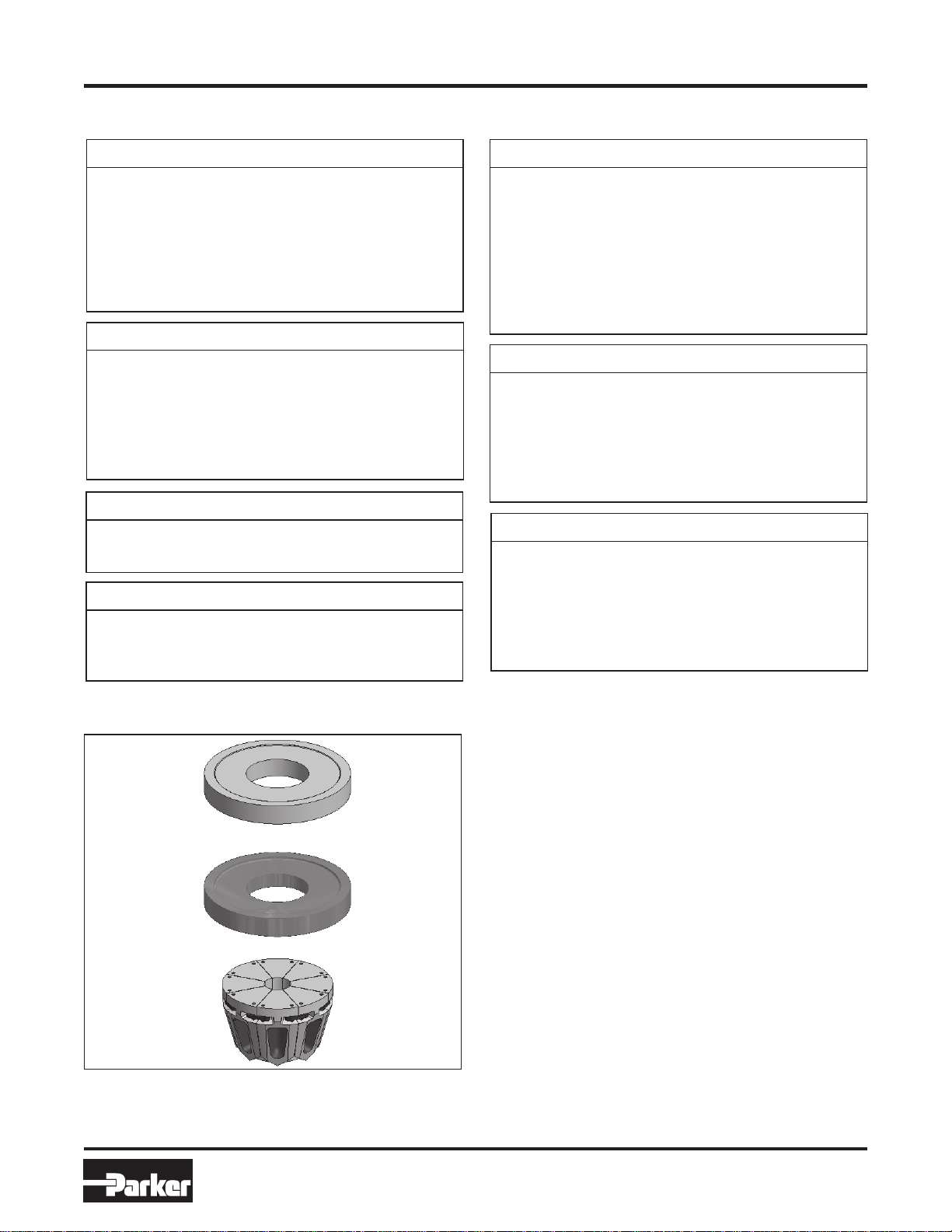
Silver
Die Ring
Black
Die Ring
Die Set
Figure 10: Die Rings and Die Set
81 Series Fittings Dies (Silver)
80C-V12 Size -12 (3/4") Color Coded Green
80C-V16 Size -16 (1") Color Coded Black
80C-V20 Size -20 (1-1/4”) Color Coded White
Operations and Crimping
HY Series Fitting Dies for AX hose (Silver)
80C-H585 Size -4 (1/4") Color Coded Brown
80C-H735 Size -6 (3/8") Color Coded Brown
80C-H840 Size -8 (1/2") Color Coded Brown
80C-H970 Size -10 (5/8") Color Coded Brown
80C-H1120 Size -12 (3/4") Color Coded Brown
80C-H1365 Size -16 (1") Color Coded Brown
HY Series Fitting Dies for BXX hose (Silver)
80C-H605 Size -4 (1/4") Color Coded Brown
80C-H775 Size -6 (3/8") Color Coded Brown
80C-H885 Size -8 (1/2") Color Coded Brown
80C-H1010 Size -10 (5/8") Color Coded Brown
80C-H1170 Size -12 (3/4") Color Coded Brown
80C-H1465 Size -16 (1") Color Coded Brown
The PHastkrimp Model 89C-061/062 is shipped without
dies.
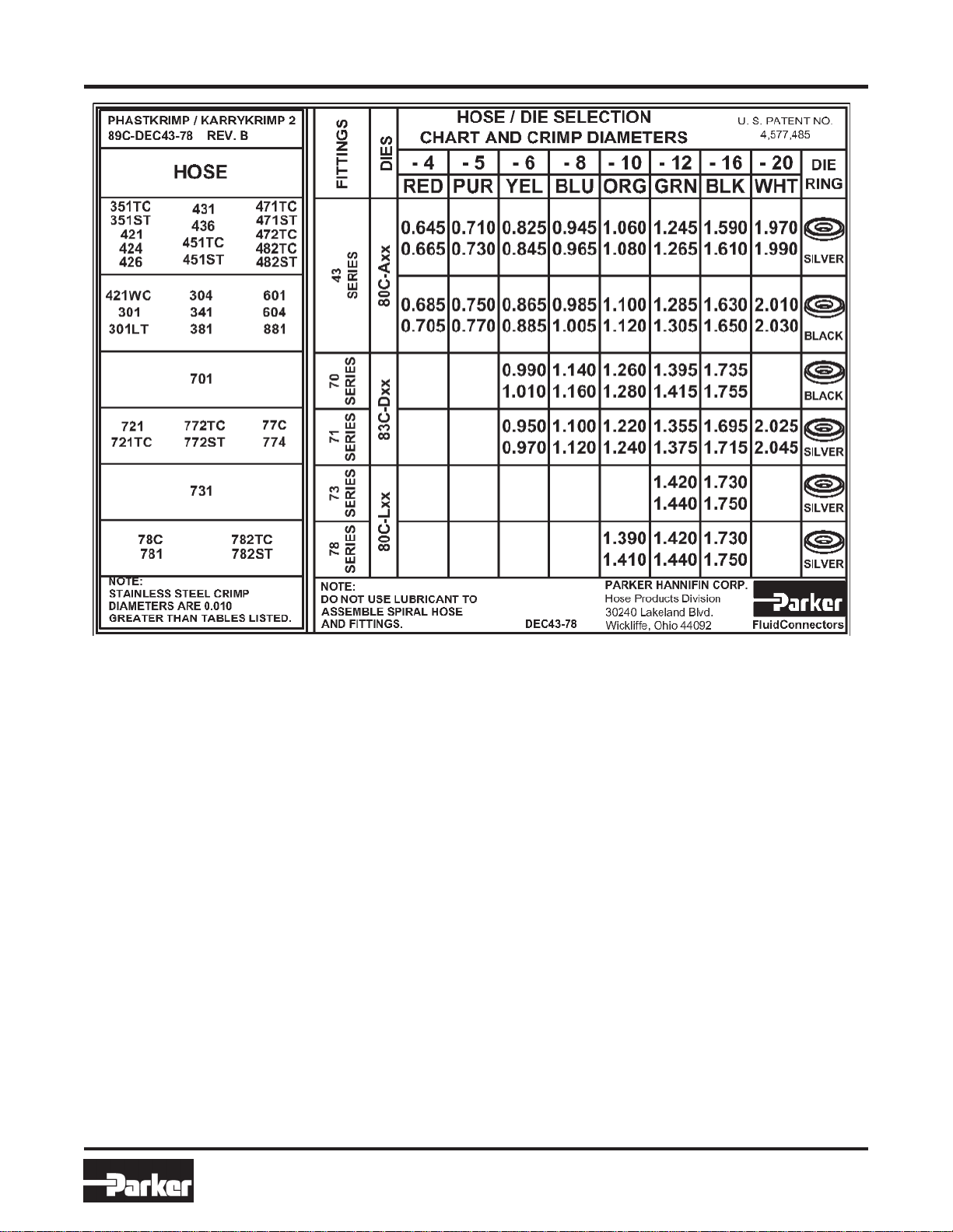
The 43 Series dies are silver and inserts are color coded
by size. Refer to the die selection chart above, Parker
Catalog 4400 or CrimpSource online, at
www.parkerhose.com to determine which die set and die
ring to use when crimping a particular fitting, hose size
andtype.
The following tooling is used for crimping:
85C-R01 Silver Die Ring
To determine when to use, refer to die selection chart in
Parker Catalog 4400 or decal on side of crimper.
85C-R02 Black Die Ring
To determine when to use, refer to die selection chart in
Parker Catalog 4400 or decal on side of crimper.
See above for die set part numbers.
www.comoso.com