Parker Racor GreenMAX 4400 Series Quick guide

All products manufactured or distributed by Racor are subject to the following, and only the following, LIMITED EXPRESS WARRANTIES, and no others: For a period of one (1) year from and after the date of purchase
of a new Racor product, Racor warrants and guarantees only to the original purchaser-user that such a product shall be free from defects of materials and workmanship in the manufacturing process. The warranty
period for pumps and motors is specifically limited to ninety (90) days from date of purchase. A product claimed to be defective must be returned to the place of purchase. Racor, at its sole option, shall replace the
defective product with a comparable new product or repair the defective product. This express warranty shall be inapplicable to any product not properly installed and properly used by the purchaser-user or to any
product damaged or impaired by external forces.
THIS IS THE EXTENT OF WARRANTIES AVAILABLE ON THIS PRODUCT. RACOR SHALL HAVE NO LIABILITY WHATSOEVER FOR CONSEQUENTIAL DAMAGES FLOWING FROM THE USE OF ANY DEFECTIVE
PRODUCT OR BY REASON OF THE FAILURE OF ANY PRODUCT. RACOR SPECIFICALLY DISAVOWS ALL OTHER WARRANTIES, EXPRESS OR IMPLIED INCLUDING, WITHOUT LIMITATION, ALL WARRANTIES OF
FITNESS FOR A PARTICULAR PURPOSE (EXCEPT FOR THOSE WHICH APPLY TO PRODUCT OR PART THEREOF THAT IS USED OR BOUGHT FOR USE PRIMARILY FOR PERSONAL, FAMILY, OR HOUSEHOLD
PURPOSES), WARRANTIES OF DESCRIPTION, WARRANTIES OF MERCHANTABILITY, TRADE USAGE OR WARRANTIES OR TRADE USAGE.
Warning! Failure or improper selection or improper use of the products and/or systems described herein or related items can cause death, personal injury and property damage. This document and other information
from Parker Hannifin Corporation, its subsidiaries and authorized distributors provide product and/or system options for further investigation by users having technical expertise. It is important that you analyze all
aspects of your application and review the information concerning the product or system in the current product catalog. Due to the variety of
operating conditions and applications for these products or systems, the user, through its own analysis and testing, is solely responsible for making
the final selection of the products and systems and assuring that all performance, safety and warning requirements of the applications are met. The
products described herein, including with limitation, product features, specifications, designs, availability and pricing, are subject to change by
Parker Hannifin Corporation and its subsidiaries at any time without notice.
The following statement is required pursuant to proposition 65, applicable in the State of California: ‘This product may contain a chemical known to
the State of California to cause cancer or reproductive toxicity’.
GreenMAX 4400 Series
Installation and Service Instructions
3/8 in. (8 mm)
diameter
clearance for
fasteners.
5.91 in.
(15.0 cm)
TOP VIEW
Vent
Plug
Hand Actuated Primer Pump
OUTOUT
IN IN
• Read all instructions before
beginning installation. Improper
installation could cause personal
injury or property damage.
• Mounting fasteners and inlet/
outlet port fittings not included.
Specifications:
• Fuel Ports: 7/8”-14 UNF (SAE J1926)
• Max. Flow Rate: 120 GPH (454 LPH)
• Clean Pressure Drop (@120 GPH):
0.4 PSI (0.03 bar)
• Max. Allowable Pressure:
30 PSI (2.07 bar)
• Bowl Capacity: 10.1 oz (300 ml)
• Particulate Removal Efficiency
(SAE J1985): 90-98%, depending on
micron rating of filter used
• Water Removal Efficiency
(SAE J1839): min. 95%
• Ambient Temp. Range:
-22o to +212oF (-30oto +100oC),
Max. Fuel Temp: 185oF (85oC)
• Suction-side installations
recommended
• Do not use on gasoline applications
Water/Contaminant Drain
14.3 in.
(36.3 cm)
6.32 in.
(16.1 cm)
Replacement Parts
1. RK61713 - Fill Port Plug Kit
2. N/A - Housing/Head Assembly Kit
(no service kit available)
3. N/A - Bowl O-ring Kit
(included with replacement filter)
4. Replacement Filters
(includes bowl O-ring)
R61691S (2 micron),
R61691T (10 micron),
R61691P (30 micron)
5. RK6166301 - Clear Bowl Kit, no heater
RK6166302 - Clear Bowl Kit, 12vdc heater
RK6166303 - Clear Bowl Kit, 24vdc heater
6. RK33802 - WIF Sensor Assembly
Instruction Part Number 14461 Rev -
1
2
3
4
5
6
Maintain a clearance of at
least 4 in. (10.2 cm) below
filter assembly to service the
filter and drain the bowl.
Optional Bypass Installation and Operation
(allows user to service filter without shutting down engine)
Valves 1 2 3
Filter On-line Open Open Closed
Filter Off-line Closed Closed Open
Valve 1 Valve 2
If fuel tank is above filter level,
head pressure should not
exceed maximum PSI of filter.
Fuel Tank
(Pressure Side Installation)
Install a shut-off valve
when fuel tank level is
higher than filter.
If fuel tank is below filter level,
lift should not exceed 4 inHg.
Fuel Tank
(Ideal Vacuum
Side Installation)
Fuel Tank
(Vacuum Side Installation)
Install a check valve, with light or
no restriction, when tank is lower
level than filter to maintain prime.
Pressure Side:
Fuel transfer pump not to exceed
maximum PSI or flow rate of filter.
Not ideal - pumps emulsify water
hindering filter performance.
Fuel Transfer Pump
(IDEAL vacuum side
installation)
Engine
Valve 3
Plug any unused fuel ports.

Refer to Mounting/Installation Diagrams on
page one and install as follows (new install):
1. Engine must be off and cool to touch.
2. Apply motor oil to o-rings on UNF/SAE inlet/
outlet ttings.
3. Thread ttings into appropriate fuel ports and
tighten snugly. Plug unused ports (if any) with
port plugs and tighten snugly.
4. Mount lter vertically in a protected area
away from ying debris and heat sources.
Maintain at least 4.0” (10.2 cm) of clearance
below lter for draining water and servicing
lter.
5. Attach fuel lines to lter port ttings. Avoid
tight bends and rubbing areas when routing
hose.
6. Connect water probe and heater wires, if
equipped.
7. Proceed to ‘Priming’ section.
Priming
1. Use a 1˝ open-end wrench to loosen vent
plug and bleed trapped air. Prime lter
by operating hand primer pump until fuel
spills out of vent port.
2. Close vent plug snugly. Or use a 1˝ open-
end wrench to tighten the vent plug.
3. Verify all other connections are tight.
4. Start engine and check for leaks. Correct
as necessary with engine off.
Service
Filter replacement frequency is determined
by contamination level in fuels. Fuel ow to
engine becomes restricted as lter gradually
plugs with contaminants, resulting in
noticeable power loss and/or hard starting.
As a guideline, change lter every 500
hours, 10,000 miles, every other oil change,
annually, or at rst indication of power
loss, whichever occurs rst. Always carry
extra replacement lters as one tankful of
excessively dirty fuel can quickly plug a
lter.
1. Engine must be off and cool to touch.
2. Close all fuel valves, if applicable, to make
sure excess fuel does not spill during
servicing.
3. Disconnect water probe and heater
connectors, if equipped.
4. Open vent plug on mounting head.
5. Drain unit of fuel, into a suitable container,
by turning drain on bottom of bowl.
6. Remove bowl and lter. Dispose of lter
properly. Bowl is reusable.
7. Lubricate new lter seals with motor oil or
clean fuel and install with new lter.
Installation Guidelines
8. Re-install bowl and tighten snugly by
hand or using a bowl wrench.
9. Connect water probe and heater
connectors, if equipped.
10. Open all fuel valves, if applicable.
11. Proceed to ‘Priming’ section.
Draining the Bowl
Water is heavier than fuel and will settle to
bottom of the bowl and appear different
in color if collected in a clear jar. In high
humidity environments, check bowl
frequently (daily if a poor fuel source is
suspected). 4400 Series bowls are equipped
with a water sensor probe and will alert
operator of a high water condition in the
lter.
1. Make sure engine is off and cool to touch.
2. Open vent plug using a 1” wrench.
3. Drain water from lter by opening self-
venting drain. Close as soon as all water
has evacuated.
If drain is open too long, the entire lter
may drain completely of water and fuel.
4. Follow ‘Priming’ section.
Troubleshooting
If lter fails to hold prime, rst check vent
plug, drain valve, ttings, head, lter, and
bowl are properly tightened. Next, check
fuel line connections and verify they are free
of pinches or unnecessary bends and check
to see if fuel tank strainer (or pick-up tube) is
clogged. If problems persist and lter is new,
call Technical Support at 800-344-3286,
7 AM to 4 PM, Pacic Time.
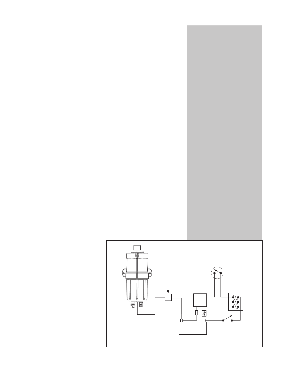
In-Bowl Heater
Note: Electric heaters must not be used
in gasoline applications.
The in-bowl heater is a cold weather
starting aid with an internal automatic
thermostat that turns the heater on
if fuel temperature drops below 45°F
(7°C). Heat is supplied just below the
filter to melt wax crystals and allow fuel
to efficiently pass through. The heater
will automatically turn off at about 75°F
(24°C). The heater is available in 12
vdc (200 watt) or 24 vdc (200 watt).
The heater is operated by turning on
the ignition switch for a minimum of 5
minutes prior to starting the engine.
Customer Supplied Items
1. Due to heater power demand, 21
amps for 12 vdc and 11 amps
for 24 vdc, an additional relay is
recommended for safest method of
installation. Racor offers two relay
kits (sold separately), RK 11861 for
12 vdc systems or RK11862 for
24 vdc systems. These kits include
an in-line fuse holder (and fuse).
2. An on-off toggle switch may be used
to control power to heater relay. This
allows the operator to cut power
to heater relay during summer or
when servicing the filter in cold
environments.
3. All wires should be 14 AWG
(American Wire Gauge), minimum.
Installation
1. Either heater wire may be used for Hot
(+) or Ground (-).
2. Wire/terminal connections should be
soldered and crimped.
3. Run wires in protected locations.
Avoid hot surfaces and places that
could pinch or rub on the wires.
Heater connector is
a Sebro 4661958.
Customer
supplied
connector
* Use a 15 amp fuse and resistor with 24 vdc systems.
Battery
- + Ignition
Switch
*fuse
*resistor
Relay
C4 B2
A5 E3
Fuse Box
1 amp
fuse
Manual on-off
switch (optional)
Maximum power requirement for in-bowl heater option: 12vdc (200W) = 16.6 amps,
24vdc (200W) = 8.3 amps. Use a Racor heater relay, if needed—sold separately.
Table of contents
Other Parker Heater manuals
Popular Heater manuals by other brands

Plein Air
Plein Air TV-SL instruction manual

DELTACALOR
DELTACALOR STENDINO 300 W instruction manual

Berko
Berko FRA series Installation & maintenance instructions

GHP Group
GHP Group M75DGD User's manual and operating instructions

EOS
EOS Vitae protect Assembly and operating instruction

Dimplex
Dimplex DHCER20 instruction manual

Wardenaar Infrarood Verwarming
Wardenaar Infrarood Verwarming IP55 Series manual

EUROLAMP
EUROLAMP FH12W instructions

Calix
Calix BLM 1500 R13 troubleshooting guide

Amerec
Amerec Steamy 6.0A Installation and operating instructions

Ferroli
Ferroli BLUEHELIX PRO RRT 24 C Instructions for use & installation

XARAM Energy
XARAM Energy HT-H-0003 instruction manual