Parker P10 User manual

1
User’s
manual
Rev. 0
Januar
y
2011
PSU

Parker Hannifin S.p.A. S.B.C. Division user’s manual PSU
2
This user manual is for the standard version of the converter.
All information in this user manual, including methods, techniques and concepts described
herein, are proprietary information of Parker Hannifin Divisione S.B.C. – EME Division and
of its licensees, and they shall not be copied or used without express authorization.
Parker Hannifin S.p.A. Divisione S.B.C. is committed to a continuous product upgrade and
reserves the right to modify products and user manuals at any time without prior notice. No
part of this user manual may be howsoever reproduced without previous consent by Parker
Hannifin S.p.A. S.B.C. Division.
Cod 1101241700

Parker Hannifin S.p.A. S.B.C. Division user’s manual PSU
3
1. PSU (POWER SUPPLY UNIT) ............................................................................... 4
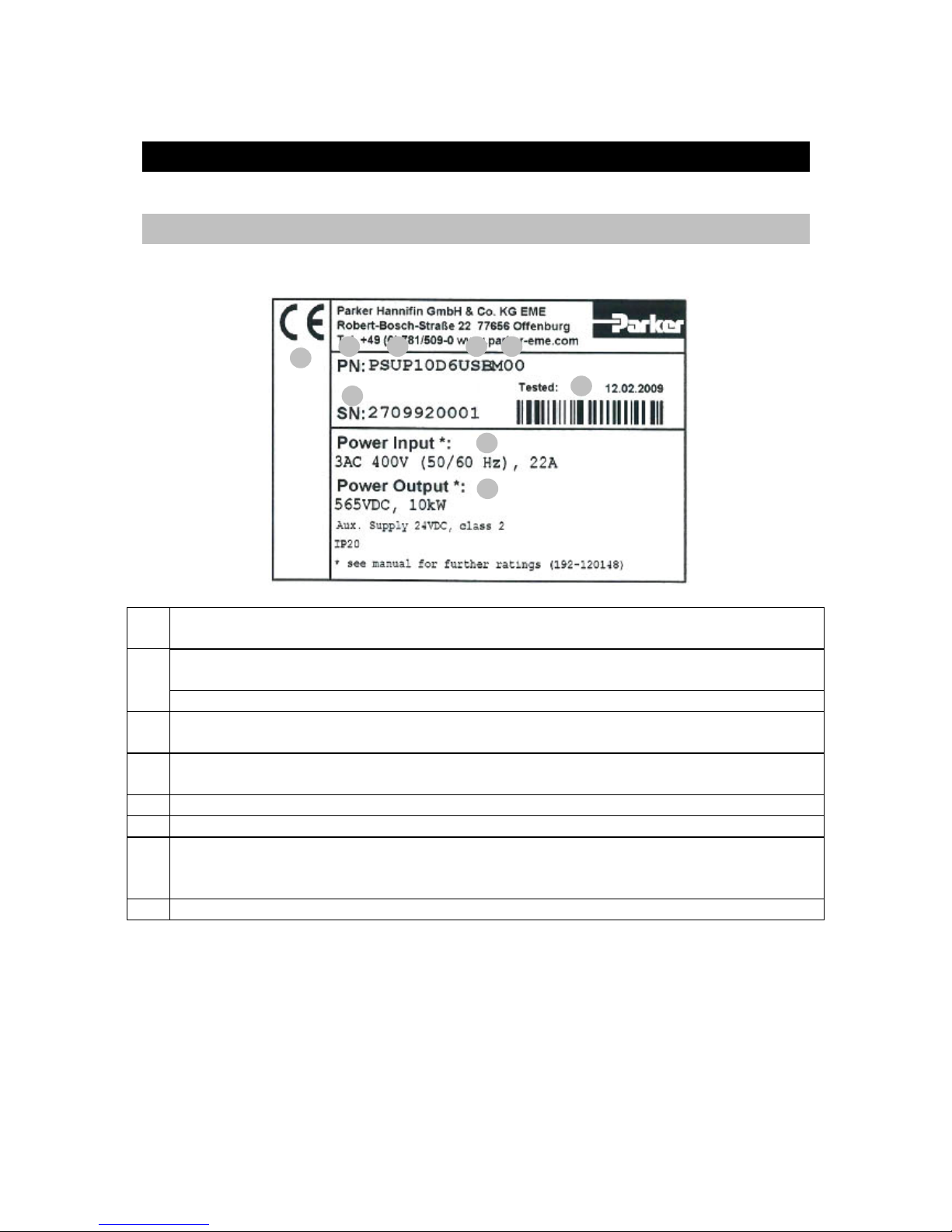
1.1.Identfication ............................................................................................................... 4
1.2.Condition of utilization .............................................................................................. 5
1.2.1.Filters .................................................................................................................. 5
1.2.2.Cable ................................................................................................................... 5
1.2.3.Grounding ........................................................................................................... 5
1.2.4.PSU protections .................................................................................................. 5
1.2.5.Hardware PSU .................................................................................................... 6
2. MOUNTING ............................................................................................................ 7
2.1.Connectors layout ....................................................................................................... 8
2.1.1.LED Status ......................................................................................................... 8
2.1.2.Signal connectors ............................................................................................... 8
3. MODULE CONNECTIONS ..................................................................................... 9
3.1.1.Rail system ......................................................................................................... 9
3.1.2.Communication connection ................................................................................ 9
3.2.Mains supply ............................................................................................................ 10
4. PARAMETERS SET-UP ...................................................................................... 10
4.1.1.Voltage supply .................................................................................................. 10
5. REVISION HISTORY OF THE USER MANUAL .................................................. 11

Parker Hannifin S.p.A. S.B.C. Division user’s manual PSU
4
1.PSU (Power Supply Unit)
1.1. Identfication
Explanation:
1 Type designation
The complete order designation of the device (2 - 4).
2
PSUPx0: Mains module 3AC 230...480V, nominal power in 1kW (10=10kW, 20=20kW,
30=30kW)
D6: Designation nominal supply
3 Configuration and parameterization interface
USB: USB connection
4 Options
Mxx: I/O extension
5 Unique number of the particular device
6 Date of factory test
7
Nominal supply voltage
Power Input: Input supply data
Power Output: Output data
8 CE compliance
1 2
3
4
5 6
7
8
7

Parker Hannifin S.p.A. S.B.C. Division user’s manual PSU
5
1.2. Condition of utilization
1.2.1. Filters
A mains filter is required in the mains input line if the motor cable exceeds a certain length.
Filtering can be provided centrally at the plant mains input or separately at the mains input to
each axis combination.
The following mains filters are available for independent utilization:
PSU Order No. Condition
P10 NFI03/01 Reference axis combination 6x10m
P10 NFI03/02 Reference axis combination 6x50m
P20-P30 NFI03/03 Reference axis combination 6x50m
1.2.2. Cable
PSU Model P10 P20-P30
24VDC
X9
Section 4mm2 (AWG8) 4mm2 (AWG8)
Tightening torque 1.2 Nm (M5) 1.2 Nm (M5)
Braking resistor
X40
Section 0.25÷4mm2 (AWG23÷11) 0.25÷4mm2 (AWG23÷11)
Tightening torque 0.5 Nm (M4) 0.5 Nm (M4)
Mains
X41
Section 0.5÷6mm2 (AWG20÷10) 0.5÷16mm2 (AWG20÷6)
Tightening torque 1.2 Nm (M5) 1.7 Nm (M5)
PE Section 10mm2 (AWG6)
1.2.3. Grounding
Connect the filter housing and the PSU to the cabinet frame, making sure that the contact area
is adequate and that the connection has low resistance and low inductance.
Never mount the filter housing and the device on paint-coated surfaces!
1.2.4. PSU protections
Mains connection
P10 P20 P30
Fuse
(short
circuit)
25A
MTP: S203UP-K
25(480VAC)
50A
MTP: S203U-K
50(440VAC)
2 circuit breakers in line
are required
63A
MTP: S203U-K
63(440VAC)
2 circuit breakers in line
are required
Control voltage 24VDC
Fuse Delayed action fuse, due to capacitive load
Short-circuit proof conditional (internally protected with 3.15AT)

Parker Hannifin S.p.A. S.B.C. Division user’s manual PSU
6
1.2.5. Hardware PSU
Description UdM Value
Models - P10 P20 P30
Supply voltage (3AC±10% 50-60Hz) VAC 230 400 480 230 400 480 230 400 480
Rated input current Arms 22 22 18 44 44 35 50 50 42
Rated output current Arms 18 18 15 36 36 30 41 41 36
Peak output current (< 5 sec) Arms 36 36 30 72 72 60 82 82 72
Power kW 6 10 10 12 20 20 17 30 30
Internal capacitance µF 550 1175 1175
Total capacity applicable µF 2400 5000 5000
External braking resistor
Minimum braking resistance Ω 27 15 10
Recomended nominal power W 500 ÷ 1500 500 ÷ 3500 500 ÷ 5000
Pulse power (1s) kW 22 40 60
Maximum permissibile peak current A 13 15 15
Control stage
Supply voltage V= 21…27VDC
Max ripple V
p
k
pk
0,5
Current A 0,2 0,3 0,3
EMC Filter - (see filters table)

Parker Hannifin S.p.A. S.B.C. Division user’s manual PSU
7
2.Mounting
100mm
360mm
263mm
96mm
4
00mm
90°
50,5mm
101mm
PSU Weight
Size 1 (P10) 3,95 kg
Size 2 (P20, P30) 6,5 kg (P20)
Dimensions
Size
Lenght
[mm]
Height
[mm]
Depht (*)
[mm]
1 50 360
(410**) 270
2 100
(*) without connectors
(**) with clamps

Parker Hannifin S.p.A. S.B.C. Division user’s manual PSU
8
2.1. Connectors layout
2.1.1. LED Status
STATUS LED green LED red
No 24Vdc Off Off
Error of main module Off On
Pow. Volt. is built up - Flashes quickly
Phase failure On Flashes slowly
Address CPU active Flashes quickly -
Address CPU completed Flashes slowly -
Serial communication error Flashes quickly Flashes quickly
Ready On Off
2.1.2. Signal connectors
X41
Mains
X40
Braking resistor
1 L1 +R + Braking resistor No short-circuit
protection
2 L2 -R - Braking resistor
3 L3 PE PE
4 PE T1R Temperature switch (*)
T2R Temperature switch (*)
X9
24VDC
(*) If the external braking resistor hasn’t the
temperature sensor, connect T1R to T2R.
1 +24V
2 0Vdc
Address setting
USB interface
RS485
24Vdc supply
Main supply Braking resistor
Led
PE

Parker Hannifin S.p.A. S.B.C. Division user’s manual PSU
9
3.Module connections
3.1.1. Rail system
External components may not be connected to the rail system.
Maximum no. of TPDM modules in a combination: 15 modules
3.1.2. Communication connection
24Vdc
- DCbus
Earth
+ DCbus
0Vdc Use the dedicate fixing plates.
On the right side of the last module, and on the
left side of the first module insert the closing
protection:
IN
OUT
IN
OUT
Protective covers: the user is
responsible for protective covers
and/or additional safety measures in
order to prevent damages to persons
and electric accidents.
Address setting
Switch Value upon ON
1 16
2 32
3 64
Range: 0,16,32,48,64,80,96,112
Settings: left: OFF
right: ON
1st Module address = basic address
IN
OUT
The communication in the axis combination is implemented via a SSK28
cable and double RJ45 sleeves on the device top. Beginning with the TPD
(mains module) the connection is always made from X30 to X31 of the
next device. On the first device (X31) and the last device (X30) in the
multi-axis combination, a bus termination plug (BUS07/01) is required.
Serial connection of up to 32 axes (or 15 modules)
Caution! Risk of Electric Shock.
Discharge time of the bus capacitor
is a
pp
rox. 10 minutes.

Parker Hannifin S.p.A. S.B.C. Division user’s manual PSU
10
3.2. Mains supply
The PSU series is designed for fixed connection to TN networks (TN-C, TN-C-S or TN-S).
Please note that the line-earth voltage may not exceed 300VAC.
• When grounding the neutral conductor, mains voltages
of up to 480VAC are permitted.
• When grounding an external conductor (delta mains,
two-phase mains), mains voltages (external conductor
voltages) of up to 300VAC are permitted.
Servo controllers which are to be connected to an IT network must be provided with a
separating transformer. Then the PSU device is operated locally like in a TN network. The
secondary sided center of the separating transformer must be grounded and connected to the
PE connector of the PSU.
4.Parameters set-up
N.B.: This operation must be executed only by the first axis connected to the PSU.
4.1.1. Voltage supply
The default status of the drive is configured to 400VAC (=560V DC). For all other cases, it’s
necessary to set the correct value of the voltage [3-phase VACsupply * √2 = VDCbus]:
230V AC 3-phase Pr206 = 325
400V AC 3-phase Pr206 = 565
480V AC 3-phase Pr206 = 680
To activate the new configuration, it’s necessary to save the parameter and restart the PSU
unit.

Parker Hannifin S.p.A. S.B.C. Division user’s manual PSU
11
5.Revision history of the User Manual
- Rev 0 – January 2011
First edition
For other informations log into website www.sbcelettronica.com. Arranges to the manual data can be made by
the manufacturer without advance notice. The data shown in the manual correspond to the specifications
relating to the revision date

This manual suits for next models
2
Table of contents
Other Parker Power Supply manuals
Popular Power Supply manuals by other brands

Tycon Power Systems
Tycon Power Systems UPSPro instructions

ZyXEL Communications
ZyXEL Communications BPS-120 user guide

Lonza
Lonza FlashGel 57068 instruction manual

C-TEC
C-TEC BF560-24 installation instructions

EGS
EGS Appleton JBR Series Instruction for installation and maintenance

Pulsar
Pulsar EN54C-LCD Series user manual

Notifier
Notifier APS-6R manual

TET Electronics
TET Electronics ARGOS-500 instruction manual

D-Link
D-Link mydlink DSP-W215 Quick installation guide

Jackery
Jackery JE-1500B user manual

Tru-Test
Tru-Test 0.04 J user manual

Rockwell Automation
Rockwell Automation Allen-Bradley 1606-XLB90EQ installation instructions