Parker PSSSE24A Installation and maintenance instructions

Introduction
Follow these instructions when installing, operating, or servicing the
product.
Isysnet 24VDC Expansion Power Supply,
Series A
(PSSSE24A)
The 24VDC expansion power supply unit (PSSSE24A) passes 24VDC
field power to the I/O modules to the right of the power supply. This
unit extends the backplane bus power for up to 17 I/O modules to the
right of the supply and creates a new field voltage partition.
The expansion power supply also separates field power from I/O
modules to the left of the unit, effectively providing functional and
logical partitioning for:
• separating field power between input and output modules
• separating field power to the analog and digital modules
• grouping modules to perform a specific task or function
You can use multiple expansion power units with the I/O adapters
to assemble a full system. For instance, if you are using the
PSSCDM12A or PSSCDM18PA adapter, you may use a PSSSE24A
expansion power unit to add additional modules in 5 to 17 module
increments. For example, if you had a 36 module system with a I/O
adapter, you would have two PSSSE24A expansion power units
to provide more PointBus current for modules to the right of the
supply.
Installation & Service Instructions
E105P
Isysnet 24VDC Expansion Power
Supply, Series A (PSSSE24A)
ISSUED: January, 2007
Supersedes: June, 2005
Doc.# E105P, ECN# 060961, Rev. 2
Do not connect 120/240VAC to the PSSSE24A terminals.
Damage to the supply will result.
!
ATTENTION
You can only use the PSSSE24A expansion power unit with
the I/O adapters.
!
ATTENTION
WARNING
FAILURE OR IMPROPER SELECTION OR IMPROPER USE OF THE
PRODUCTS AND/OR SYSTEMS DESCRIBED HEREIN OR RELATED
ITEMS CAN CAUSE DEATH, PERSONAL INJURY AND PROPERTY
DAMAGE.
This document and other information from Parker Hannifin Corporation,
its subsidiaries and authorized distributors provide product and/or system
options for further investigation by users having technical expertise. It
is important that you analyze all aspects of your application, including
consequences of any failure and review the information concerning the
product or systems in the current product catalog. Due to the variety of
operating conditions and applications for these products or systems, the
user, through its own analysis and testing, is solely responsible for making
the final selection of the products and systems and assuring that all
performance, safety and warning requirements of the application are met.
The products described herein, including without limitation, product
features, specifications, designs, availability and pricing, are subject to
change by Parker Hannifin Corporation and its subsidiaries at any time
without notice.
EXTRA COPIES OFTHESE INSTRUCTIONS ARE AVAILABLE FOR INCLUSION
IN EQUIPMENT / MAINTENANCE MANUALSTHAT UTILIZETHESE PRODUCTS.
CONTACT YOUR LOCAL REPRESENTATIVE.
!
Pneumatic Division
Richland, Michigan 49083
Safety Guide
For more complete information on recommended application guidelines, see
the Safety Guide section of Pneumatic Division catalogs or you can download
the Pneumatic Division Safety Guide at: www.parker.com/safety
WARNING
• To avoid unpredictable system behavior that can cause personal
injury and property damage:
• Disconnect electrical supply (when necessary) before installation,
servicing, or conversion.
• Disconnect air supply and depressurize all air lines connected to this
product before installation, servicing, or conversion.
• Operate within the manufacturer’s specified pressure, temperature,
and other conditions listed in these instructions.
• Medium must be moisture-free if ambient temperature is below
freezing.
• Service according to procedures listed in these instructions.
• Installation, service, and conversion of these products must be
performed by knowledgeable personnel who understand how
pneumatic products are to be applied.
• After installation, servicing, or conversion, air and electrical supplies
(when necessary) should be connected and the product tested for
proper function and leakage. If audible leakage is present, or the
product does not operate properly, do not put into use.
• Warnings and specifications on the product should not be covered by
paint, etc. If masking is not possible, contact your local representative
for replacement labels.
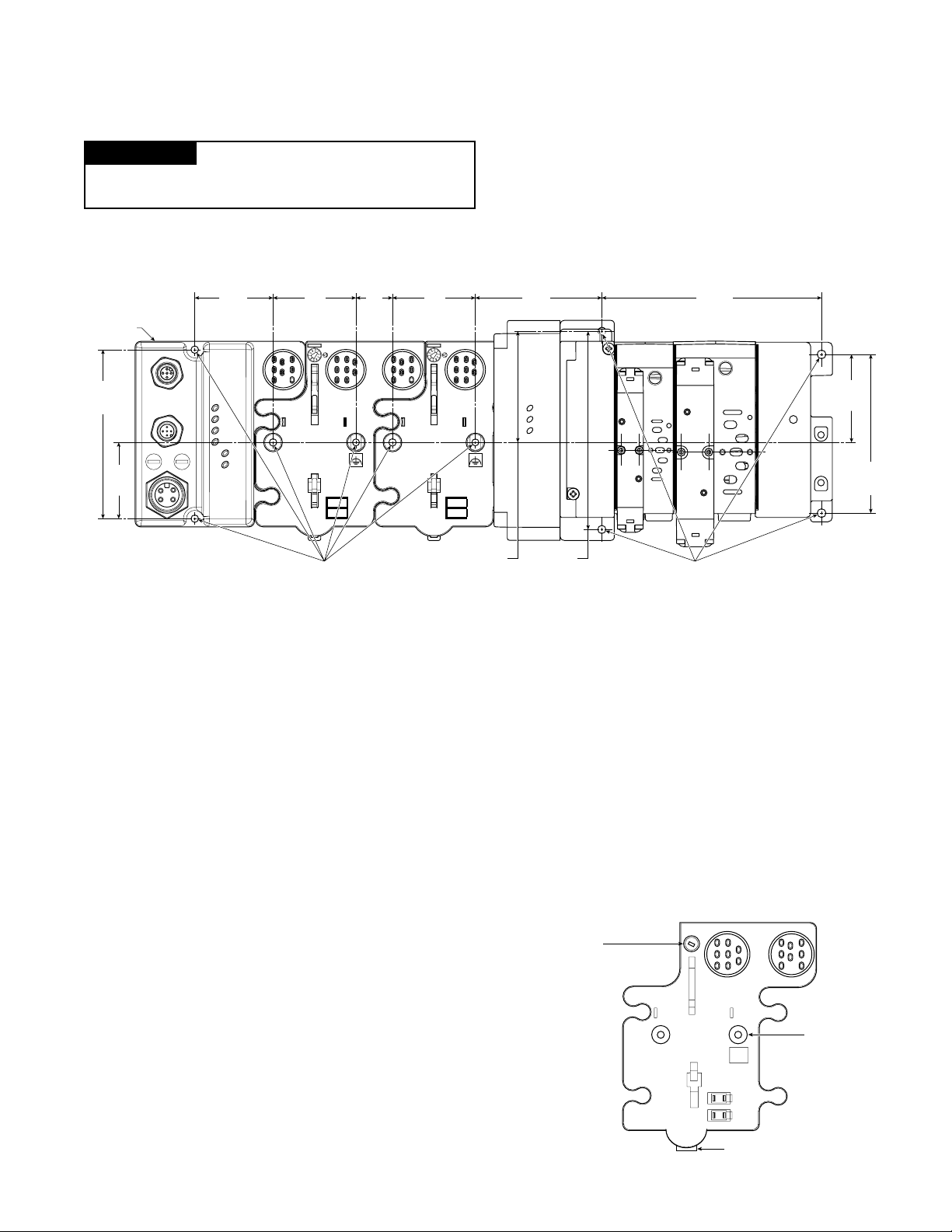
!
PSSSE24A
24V dc Power Supply
System
Power
Field
Power
A
U
X
P
O
W
E
R
PSSSE24A
24VDC
Expansion
Power Supply
Wire
Marker
Mini 7/8”
Power
Connector
LED
Indicators

Isysnet 24VDC Expansion Power Supply, Series A (PSSSE24A) E105P
2
Important User Information
Solid state equipment has operational characteristics differing from
those of electromechanical equipment. Safety Guidelines for the
Application, Installation and Maintenance of Solid State Controls
(available online at www.parker.com/pneu/isysnet) describes some
important differences between solid state equipment and hard-wired
electromechanical devices. Because of this difference, and also
because of the wide variety of uses for solid state equipment, all persons
responsible for applying this equipment must satisfy themselves that
each intended application of this equipment is acceptable.
In no event will Parker Hannifin Corporation be responsible or liable
for indirect or consequential damages resulting from the use or
application of this equipment.
The examples and diagrams in this manual are included solely
for illustrative purposes. Because of the many variables and
requirements associated with any particular installation, Parker
Hannifin Corporation cannot assume responsibility or liability for
actual use based on the examples and diagrams.
No patent liability is assumed by Parker Hannifin Corporation with
respect to use of information, circuits, equipment, or software
described in this manual.
Reproduction of the contents of this manual, in whole or in part, without
written permission of Parker Hannifin Corporation is prohibited.
Throughout this manual we use notes to make you aware of safety
considerations.
WARNING Identifies information about practices or
circumstances that can cause an explosion in
a hazardous environment, which may lead to
personal injury or death, property damage, or
economic loss.
IMPORTANT
Identifies information that is critical for successful
application and understanding of the product.
ATTENTION Identifies information about practices or
circumstances that can lead to personal injury
or death, property damage, or economic loss.
Attentions help you:
• Identify a Hazard
• Avoid a Hazard
• Recognize the Consequence
SHOCK HAZARD
Labels may be located on or inside the
equipment to alert people that dangerous
voltage may be present.
BURN HAZARD Labels may be located on or inside the
equipment to alert people that surfaces may
be dangerous temperatures.
!
!
Environment and Enclosure
This equipment is intended for use in overvoltage Category
II applications (as defined in IEC publication 60664-1), at
altitudes up to 2000 meters without derating. This equipment
is considered Group 1, Class A industrial equipment according
to IEC/CISPR Publication 11. Without appropriate precautions,
there may be potential difficulties ensuring electromagnetic
compatibility in other environments due to conducted as well as
radiated disturbance. This equipment is supplied as “enclosed”
equipment. It should not require additional system enclosure
when used in locations consistent with the enclosure type
ratings stated in the Specifications section of this publication.
Subsequent sections of this publication may contain additional
information regarding specific enclosure type ratings, beyond
what this product provides, that are required to comply with
certain product safety certifications.
NOTE: See NEMA Standards publication 250 and IEC
publication 60529, as applicable, for explanations of the degrees
of protection provided by different types of enclosure. Also,
see the appropriate sections in this publication, as well as the
publication E115P (“Industrial Automation Wiring and Grounding
Guidelines”), for additional installation requirements pertaining
to this equipment.
!
ATTENTION
Preventing Electrostatic Discharge
This equipment is sensitive to electrostatic discharge, which
can cause internal damage and affect normal operation. Follow
these guidelines when you handle this equipment:
• Touch a grounded object to discharge potential static.
• Wear an approved grounding wriststrap.
• Do not touch connectors or pins on component boards.
• Do not touch circuit components inside the equipment.
• If available, use a static-safe workstation.
• When not in use, store the equipment in appropriate static-
safe packaging.
!
ATTENTION

Isysnet 24VDC Expansion Power Supply, Series A (PSSSE24A) E105P
3
Inches
(mm)
Adapter
2.0
(50)
2.0
(50)
1.9
(47.2)
4.02
(102)
1.81
(46)
4.32
(109.8)
5.39
(137.0)
Drill and Tap
for M4 Screw
2.39
(60.7)
3.02
(76.6)
3.13
(79.4)
5.98*
(151.9)
0.87
(22)
Drill and Tap
for M6 Screw
Mount the I/O Base
To mount the I/O base on a wall or panel, use the screw holes
provided in the base.
IMPORTANT
The I/O module must be mounted on a grounded metal mounting
plate or other conductive surface.
A mounting illustration for the base with an adapter is shown below.
Ground Lug
Connection
Latching Mechanism
Mounting Base
Keyswitch-
Set to position 1
for the PSSSE24A
dc expansion
power supply
Install the Mounting Base as Follows:
1. Lay out the required points as shown above in the drilling
dimension drawing.
2. Drill the necessary holes for #8 (M4) machine or self-tapping
screws.
3. Mount the base using #8 (M4) screws.
4. Ground the system using the ground lug connection. (The ground
lug connection is also a mounting hole.)
* Depending on the type and number of manifolds, this dimension
may vary. Refer to Catalog 0600P-# for additional information.

Isysnet 24VDC Expansion Power Supply, Series A (PSSSE24A) E105P
4
Wire the 24VDC Expansion Power Supply
Following are wiring instructions for the 24VDC Expansion Power
Supply.
Make sure all connectors and caps are securely tightened to
properly seal the connections against leaks and maintain IP67
requirements.
!
ATTENTION
Male In Connector (Mini 7/8”)
PSSSE24A
(view into connector)
Pin 1 - User Power +
Pin 2 - Adapter Power +
Pin 3 - Adapter Power -
Pin 4 - User Power -
Install the 24VDC Expansion Power Supply
To Install the Power Supply, Proceed as Follows:
1.
Using a bladed screwdriver, rotate the keyswitch on the mounting
base clockwise until the number 1 aligns with the notch in the
base.
2. Position the power supply vertically above the mounting base.
The module will bridge two bases.
3. Push the power supply down until it engages the orange latching
mechanism.You will hear a clicking sound when the power supply
is properly engaged. The locking mechanism will lock the power
supply to the base.
Remove the 24VDC Expansion Power Supply
From the Mounting Base
To Remove the Power Supply from the Mounting Base:
1. Put a flat blade screwdriver into the slot of the orange latching
mechanism.
2. Push the screwdriver toward the I/O module to disengage the
latch. The module will lift up off the base.
3. Pull the module off of the base.
Install a Replacement PSSSE24A to an
Existing System
1. Remove the module to the right of the power supply from the
mounting base.
2. If you have not done so already, remove the existing power supply
from the mounting base.
3. Position the replacement power supply vertically above the
mounting base.
4. Push the power supply down until it engages the orange latching
mechanism.You will hear a clicking sound when the power supply
is properly engaged and locked to the base.
5. Place the module to the right of the power supply back onto the
mounting base.
PSSSE24A
24V dc Power Supply
System
Power
Field
Power
A
U
X
P
O
W
E
R
Module Will Bridge Two Bases
Note: User power is the 24VDC power for field devices.
Adapter power is the 24VDC power for PSSSE24A. It is
converted to 5VDC to power isysNet modules.

Isysnet 24VDC Expansion Power Supply, Series A (PSSSE24A) E105P
5
Specifications
Following are specifications for the PSSSE24A Power Supply.
24VDC Expansion Power Supply - PSSSE24A
I/O Module Capacity 5 to 17 I/O modules depending on each module's current rating
Power Supply
In order to comply with CE Low Voltage Directives (LVD), you must use a Safety Extra Low
Voltage (SELV) or a Protected Extra Low Voltage (PELV) power supply to power the
adapter.
Inputs Voltage Rating 12VDC, 24VDC nominal
10-28.8VDC range
Operating Voltage 10-28.8VDC
Input Current, Maximum 6A for 10ms
Backplane Output Current 5VDC, 1.3A
Field Side Power Requirements, Maximum 24VDC (+20% = 28.8VDC) @ 400 mA
Indicators 1 Green Field Power Status Indicator
1 Green 5V System Power Indicator
Module Location Between I/O modules in system
Breaks field power bus
PointBus Output Current 1A at 10-19.2V input; 1.3A at 19.2-28.8V input
Input Overvoltage Protection Reverse polarity protected
Interruption Output voltage will stay within specifications when input drops out for
10ms at 10V with maximum load
General Specifications
Power Consumption, Maximum 9.8W @ 28.8VDC
Power Dissipation, Maximum 3.0W @ 28.8VDC
Thermal Dissipation, Maximum 10.0 BTU/hr. @ 28.8VDC
Isolation Voltage 50V rms
(continuous-voltage withstand rating) Tested at 1250VAC rms for 60s
Field Power Bus
Supply Voltage 12VDC, 24VDC nominal
Voltage Range 10-28.8VDC range
Supply Current 10A maximum
Dimensions Inches (Millimeters) 1.25H x 2.63W x 4.25D (31.75H x 66.80W x 107.95D)
Operating Temperature IEC 60068-2-1 (Test Ad, Operating Cold),
IEC 60068-2-2 (Test Bd, Operating Dry Heat),
IEC 60068-2-14 (Test Nb, Operating Thermal Shock):
-20 to 60°C (-4 to 140°F)
Storage Temperature IEC 60068-2-1 (Test Ab, Un-packaged Non-operating Cold),
IEC 60068-2-2 (Test Bb, Un-packaged Non-operating Dry Heat),
-40 to 85°C (-40 to 185°F)
Relative Humidity IEC 60068-2-30 (Test Db, Un-packaged Non-operating Damp Heat):
5-95% non-condensing
Shock IEC60068-2-27 (Test Ea, Unpackaged Shock):
Operating 30g
Non-operating 50g
Vibration IEC60068-2-6 (Test Fc, Operating):
5g @ 10-500Hz
ESD Immunity IEC 61000-4-2:
6kV contact discharges
8kV air discharges
Radiated RF Immunity IEC 61000-4-3:
10V/m with 1kHz sine-wave 80%AM from 30MHz to 2000MHz
10V/m with 200Hz 50% Pulse 100%AM at 900Mhz
10V/m with 200Hz 50% Pulse 100%AM at 1890Mhz

Isysnet 24VDC Expansion Power Supply, Series A (PSSSE24A) E105P
6
General Specifications (continued)
EFT/B Immunity IEC 61000-4-4:
±4kV at 5kHz on power ports
Surge Transient Immunity IEC 61000-4-5:
±1kV line-line(DM) and ±2kV line-earth(CM) on power ports
Conducted RF Immunity IEC 61000-4-6:
10Vrms with 1kHz sine-wave 80%AM from 150kHz to 80MHz
Emissions CSPR 11:
Group 1, Class A
Enclosure Type Rating Meets IP65/66/67 (when marked)
Mounting Base Screw Torque #8 screw, 7.5 in. lbs. in Aluminum, 16 in. lbs. in Steel
Weight Imperial (Metric) 0.637 lb. (0.289 kg)
Wiring Category11 - on power ports
Keyswitch Position 1
Certifications: (when product is marked) c-UL-us UL Listed Industrial Control Equipment, certified for US and Canada
CE European Union 89/336/EEC EMC Directive, compliant with:
EN 61000-6-4; Industrial Emissions
EN 50082-2; Industrial Immunity
EN 61326; Meas./Control/Lab., Industrial Requirements
EN 61000-6-2; Industrial Immunity
C-Tick Australian Radiocommunications Act, compliant with:
AS/NZS CISPR 11; Industrial Emissions
1. Use this Conductor Category information for planning conductor routing. Refer to Publication E115P, “Industrial Automation Wiring and
Grounding Guidelines”.
This manual suits for next models
1
Table of contents
Other Parker Power Supply manuals