Parksafe Automotive SW004SSD User manual

Operating Instructions
4CH HD DVR
Thank you for using our Mobile DVR. Please read this User’s Manual carefully to ensure that you
can use the device correctly and safely.
The contents of this manual are subject to change without notice.
V1.0

Contents
1. Specifications.......................................................................................................................................................1
2. Precautions...........................................................................................................................................................3
3. Main Features......................................................................................................................................................4
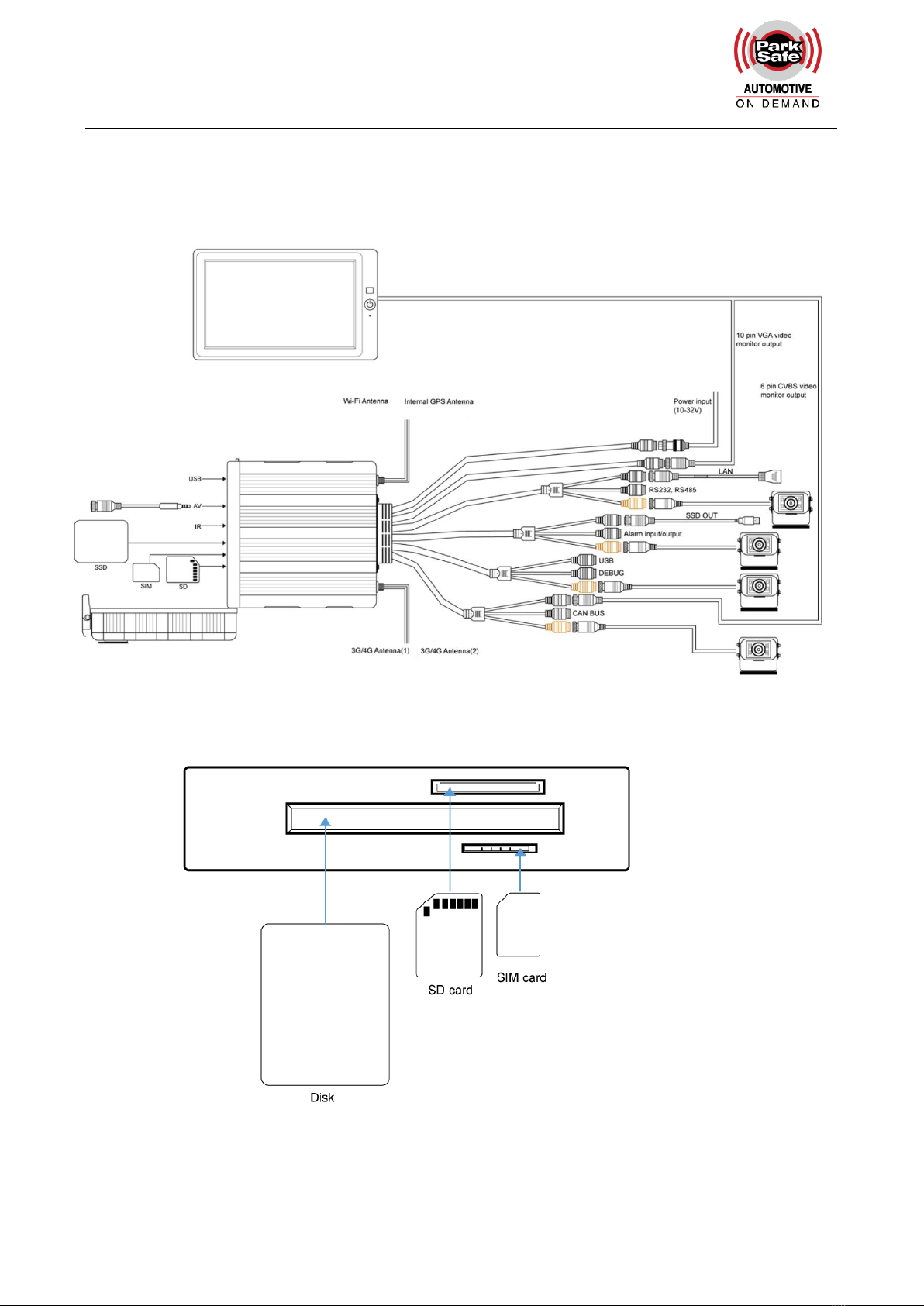
4. Wiring Diagram....................................................................................................................................................6
5. Connection - Front Panel ...................................................................................................................................7
5.1 LED..............................................................................................................................................................7
5.2 Electronic Lock...........................................................................................................................................8
5.3 Remote Controller.....................................................................................................................................8
5.4 SSD Slot.....................................................................................................................................................8
5.5 SD Card Slot..............................................................................................................................................8
5.6 USB Slot.....................................................................................................................................................9
6. Back Panel............................................................................................................................................................9
6.1 Power....................................................................................................................................................... 10
6.2 Cameras (AVIN 1~4 )............................................................................................................................ 10
6.3 LCD Monitor............................................................................................................................................ 11
6.4 Buzzer...................................................................................................................................................... 13
6.5 Recording Files Output.......................................................................................................................... 14
6.5 Alarm Interface........................................................................................................................................ 14
6.6 Panic Button (Optional)......................................................................................................................... 16
6.7 Four-in-one Antenna (GPS, 3G/4G, Wi-Fi) ........................................................................................ 19
7. The Menu........................................................................................................................................................... 19
7.1 Menu Introduction................................................................................................................................... 19
7.2 Menu Lock............................................................................................................................................... 21
7.3 Keyboard Operation Instruction........................................................................................................... 22
7.4 Manual Recording.................................................................................................................................. 25
7.5 Playback.................................................................................................................................................. 25
7.6 Logging.................................................................................................................................................... 29
7.7 Display Mode Switching........................................................................................................................ 29
7.8 System..................................................................................................................................................... 29
7.9 Disk........................................................................................................................................................... 30
7.10 Volume................................................................................................................................................... 31
8. Record Setup.................................................................................................................................................... 32
8.1 Power On Rec......................................................................................................................................... 32
8.2 Cyclic Rec................................................................................................................................................ 33
8.3 Event Rec................................................................................................................................................ 33
8.4 Video Quality........................................................................................................................................... 33
8.5 Record Channel...................................................................................................................................... 35
8.6 Event Duration........................................................................................................................................ 36
8.7 File Length............................................................................................................................................... 36

8.8 Motion Sensitivity.................................................................................................................................... 36
8.9 G-sensor Sensitivity............................................................................................................................... 37
8.10 File Type................................................................................................................................................ 44
9. Display................................................................................................................................................................ 44
9.1 Camera Display Setting......................................................................................................................... 45
9.2 Camera Name Setting........................................................................................................................... 45
9.3 System Language Setting..................................................................................................................... 46
9.4 Audio Out................................................................................................................................................. 46
9.5 OSD Display Setting.............................................................................................................................. 47
9.6 Menu on................................................................................................................................................... 48
9.7 Speed....................................................................................................................................................... 48
9.8 GPS.......................................................................................................................................................... 49
9.9 Mirror........................................................................................................................................................ 50
10. Network............................................................................................................................................................ 51
10.1 LAN and Server Setting ...................................................................................................................... 51
10.2 Wi-Fi Network Setup and Server Setup............................................................................................ 52
10.3 2G/3G/4G Control and Setup............................................................................................................. 54
10.4 Ap Internet Setup................................................................................................................................. 56
10.5 Network Status..................................................................................................................................... 56
10.6 Server..................................................................................................................................................... 58
10.7 FTP......................................................................................................................................................... 58
11. System............................................................................................................................................................. 60
11.1 Log in Setup.......................................................................................................................................... 61
Set user name and password for booting up. The initial password is 123........................................... 61
11.2 License Plate Number Setup.............................................................................................................. 61
11.3 System Time Setup.............................................................................................................................. 62
11.4 Scheduled Recording.......................................................................................................................... 65
11.5 Exception............................................................................................................................................... 66
11.6 ACC Settings........................................................................................................................................ 67
11.7 Alarm Information Setting................................................................................................................... 67
11.8 Update ................................................................................................................................................... 70
11.9 Configuration......................................................................................................................................... 75
11.10 System Info......................................................................................................................................... 76
12. FAQ.................................................................................................................................................................. 77
13. APPENDIX...................................................................................................................................................... 78
APPENDIXⅠ:Abbreviation & Description...................................................................................................... 78
APPENDIXⅡ:Accessories................................................................................................................................ 79
APPENDIX Ⅲ: Compatibility Storage List......................................................................................................... 79

1
1 Specifications
4CH HD DVR
System
Operating system
Linux
Operating interface
Graphical menu operation interface(OSD)
Video permission
Administrator & user setting
Video
Video input
4 x 1080P analog high definition
CVBS output
1CH 6pin aviation connector output PAL/NSTC
VGA output
1CH VGA output, 1080P
HDMI output
NULL
Video display
1, 2, 3, 4
Video standard
PAL: 25FPS, NTSC: 30FPS
Compression
H.264 main profile
Audio
Audio input
4 channels
Audio output
1 channel
Record format
Synchronized video & audio recording
Audio compression
ADPCM
Digital
processing &
storage
Image resolution
Max 4 x 1080P (1920X1080)
Video bit rate
64kbps~4Mbps/channel
Storage
56~2700MB/ (channel X hour)
Audio bit rate
32kbps
Storage
2.5 inch SATA SSDX1, max 2TB; SD cardX1, max 128GB
Alarm
Alarm input
6 channels
Alarm output
2 channels, 1 buzzer
Motion detection
High/low/off sensitivity adjustable
Interface for
communication
IR
1 channel
RS232
1 channel for RFID
RS485
1 channel for Panic Button
CAN
2 channels
RJ45
1 channel
USB mini-B
1 channel
USB2.0
2 channels
1 channel for copying file (SSD/ SD) and firmware upgrade
1 channel for copying SSD file (only for connecting to
computer USB)
USB3.0
NULL

2
Wireless
2G/3G/4G
Optional
Wi-Fi
Optional
Wi-Fi hot spot/AP
Optional
GPS
Internal or external GPS/GLONASS module, coordinate/speed can be encoded in
video stream and uploaded to server by wireless communication
G-Sensor
/Gyroscope
Nine axis sensor
Available
Software
Windows client
Available
iOS client
Available
Web portal
Available
Power
Input
10~32V
Output
Max Power
Consumption
60W
Standby Power
Consumption
100mW
Electrical spec
Operating temp. &
humidity
-20~+70 degree/ <100%
Super Capacitor
Available
Clock
Built-in clock, Calendar

3
2 Precautions
1. Motion detection function is set to OFF by default. Alarm files will be created When the motion
detection is set ON.
2. G-Sensor recording is recommended to set ON during driving for emergency recording use.
G-Sensor level is optional.
3. If the device could not boot up, try to remove all storage disks from the device, and then restart
it to check whether it could boot normally or not.
4. Make sure the yellow ACC wire is connected to the ignition wire and the red V+ wire to the
positive pole of the battery. In this case, the device can continue to record for some time after
the vehicle engine is off. If the ACC wire (the yellow one) and the V+ wire (the red one) are
connected directly to the positive pole of the battery, the device would keep working even if the
vehicle is switched off. If the ACC wire and the V+ wire (the red one) are connected directly to
the ignition wire of the vehicle, there is high risk that recording files before the ignition shutting
off would be damaged.
5. All the disks must be formatted on the device before they are put into use.
6. The users’ name could not be changed, while the password is editable.
7. All types of video files including event recording files are overwritten by default. If the user does
not want to overwrite the event files, please set [Event Rec. Lock] to ON which could be found
in the menu of [Event Rec.].
8. The corresponding types of SENSORs are as following:
SENSOR-I
N1
SENSOR-I
N2
SENSOR-I
N3
SENSOR-I
N4
SENSOR-I
N5
SENSOR-I
N6
ALARM INPUT 1~4
Reverse
input
Brake
input
9. The disk must be installed appropriately and well connected, otherwise the device would not
work properly.

4
3 Main Features
Appearance
Compact size and waterproof
Controlled by touch screen
All settings and operations could be done through a touch-control monitor.
Video and Audio
4 channels X 1080p,
4 video inputs with audio
2 video output with audio.
1 CVBS output (1 X 6 PIN OUT), 1 X VGA (1080P).
Recording
4CH Video & Audio Recorder with image resolution up to 1920 X 1080, G-sensor data and
GPS data
Multiple recording modes: power on recording, manual recording, schedule recording and
event recording (i.e., G-sensor recording, over-speed recording, motion detection recording,
alarm recording 1~6 and panic button recording), Cyclic recording and 10 seconds
pre-recording are also supported.
Recording files are stored in the SSD or SD card(1x128G).
Real-time recording of license plate numbers, driving speed, G-sensor/Gyroscope 6D
accelerated speed, longitude and latitude, and GPS tracking.
Preview and Playback
Support single channel or 4 channels audio and video playing back simultaneously.
Support searching recording files by dates and recording types.
Support to control the time during playing back.
Indicating recording status, alarm status and etc.
Storage Types
Support 1XSSD (2T) and 1XSD card (128G, SDHC, SDXC)
SSD is preferred. SD card could
A computer could be connected and read the SSD through the SSD-out cable
Backup

5
Support USB disk or USB hard disk to backup the recording files.
Network
Support LAN, Wi-Fi, and 3G / 4G
LAN, Wi-Fi and 3G / 4G have the sequence priority of connections. They are automatically
switched to save the data once LAN or Wi-Fi is connected.
Recording files could be uploaded to the server by FTP. Files are able to be
searched/downloaded by CMS Client;
Wi-Fi supports STATION and AP mode. Wi-Fi AP mode enables mobile devices to be
connected, and users could use mobile devices to preview and configure conveniently.
Support remote real-time video streaming and previewing
Support automatic uploading of alarm recording files, alarm information, log information and
GPS tracking route, which is convenient to analyze any abnormal conditions of vehicles and
track the vehicle
Support remote configuration and remote upgrading
Support web portal, PC Windows Client, IOS and Android app. Management could remotely
monitor vehicles by computers or mobile phones..
Alarm
6 channels of alarm inputs, 1 channel of buzzer output and 2 channels of alarm outputs
Over-speed alarm and accelerated-speed alarm
Motion detection alarm
G-sensor alarm
Panic button alarm
Charger
5V, 1.5A output from the USB interface to mobile devices.
Security
Users’ password protection. The device could NOT be accessed without password.
Support account management.

6
4 Wiring Diagram

7
5 Connection - Front Panel
5.1 LED
The red light is on constantly while the green light flickers when the device is working properly;
The red light is on constantly while the green light is off when the device is upgrading the system
5.2 Electronic Lock
Close the front cover, lock the buckle, and then lock the device with the key.
The device will stop recording and the buzzer will beep when the front cover is open or the lock
is unlocked.
① LED Indicators
⑤ IR Receiver
② Electronic lock
⑥ SD Card Slot
③ Front Cover Buckle
⑦ SSD Slot
④ USB2.0 port
⑧ SIM Card Slot

8
5.3 Remote Controller
Use the remote controller closer enough to the IR Receiver, otherwise it may not work.
5.4 SSD Slot
1XSSD (Max. 2T )
Size: 2.5 inches (70X100X7mm).
A computer could be connected and read the SSD through the SSD-out cable
5.5 SD Card Slot
1x SD (Max. 128G)
Insert、remove the SD card
Step 1: Use the key to unlock the device and open front cover

9
Step 2: Insert SD card to SD card slot
Step 3: Close the front cover and use the key to lock
5.6 USB Slot
USB 2.0/3.0, Max. Capacity 2T
6 Back Panel
①Cellular Connector, TX/RX
③Wi-Fi Connector
②Cellular Diversity Connector, Rx
④GPS Connector

10
6.1 Power
power input
Connect the 9 PIN female to the 9 PIN male on the device.
Connection
Connect ignition wire to yellow ACC, battery Positive to V+(Red wire) and Negative to GND (black
wire)
6.2 Cameras (AVIN 1~4 )
Below is the the diagram of cameras
How to connect cameras
Connect cameras to the device at the back panel via 4pin connections.

11
Connect No.1 camera to AVIN1 4PIN Aviation male.
Connect No.2 camera to AVIN2 4PIN Aviation male.
Connect No.3 camera to AVIN3 4PIN Aviation male.
Connect No.4 camera to AVIN4 4PIN Aviation male.
6.3 LCD Monitor
EDID (Extended Display Identification Data) is automatically acquired when power is connected.
Output resolution of the LCD monitor can be selected. Settings are as follows:

12
AUTO supports as below:
High definition monitors are recommended to work with the device as below:
The parameter list of high definition monitors
Description
10.1"Color monitor
7"Color monitor
System Format
CVBS
HD
AUTO
NTSC/PAL
1080P/720P

13
Resolution
1024 x 600 (RGB)
1024 x 600 (RGB)
Audio input
1 channel
1 channel
Audio output (loudspeaker)
1W
1W
VGA input
1 channel
1 channel
CVBS input
1 channel
1 channel
Trigger
No
No
Max. Brightness
500 cd/m²
450 cd/m²
Contrast
600:1
800:1
Minimum Operating Temperature
-20ºC, RH 90%
-20ºC, RH 90%
Maximum Operating
Temperature
+70ºC, RH 90%
+70ºC, RH 90%
Viewing Angle Monitor
U: 70/ D: 50, R/L: 70/70
U: 75/ D:75, R/L: 75/75
Mirror Function
No
No
Monitor Diameter (mm)
267mm (W) X 159.5mm (H) X
30mm (T)
203mm (W) X 112mm (H) X
28mm (T)
Split Screen
No
No
Volts
10-32V
10-32V
Consumption
less than 8W
less than 5W
6.4 Buzzer
If the device is not connected to a monitor, please check the recording status by the buzzer.
The buzzer would alarm if the device is not recording under Normal Mode which is set by default. To
stop the buzzer from alarming, please make sure the device is working properly.
The buzzer warning function is a as follows:
The buzzer will keep beeping for a while for all types of alarm event recording.
If the buzzer alarm is not needed, users can go to “System - Exception” page, and set Buzzer to
OFF. And please note that if the Buzzer is set to be OFF, there would be no alarm even if any event
is triggered.
If the buzzer beeps intermittently, it means that the device is unable to record.

14
Different beeping modes stand for different working status as below:
a. The electronic lock is open: one long beep and one short beep
b. No disk: one long beep and two short beeps
c. Abnormal disk system: one long beep and three short beeps
d. If the disk is well connected but the alarm video files are full : two short beeps and one
short beep
e. No camera input: two short beeps , and two short beeps after a second
f. If the disk is well connected but the device is not in recording: two short beeps and three
short beeps
6.5 Recording Files Output
Connect the3 PIN female of cable ”SSD OUT” to the 3 PIN male on the device
Connect the device to a computer by USB
A computer could be connected to the device and read the SSD through the SSD-out cable, which
enables the users to read the disk without taking it out .
6.5 Alarm Interface
Alarm interface cable
See the picture below

15
Pin Definition:
1. Below is the alarm setting. Alarm1, Alarm2, Alarm3 and Alarm4 could be renamed by users.
2. Alarm output 1 and alarm output 2 are 12V by default, which can be used as a trigger and working
together with alarm inputs. You can also set up the BUZZER as one output.
3. If Alarm input 1 is active and combined with Alarm output 1, the Alarm output 1 will output a
high-level voltage to trigger other device.
10 PIN
1
2
3
4
5
6
7
8
9
10
Colour
red
pink
blue
gray
white
purple
green
yellow
black
black
Definition
Alarm
out2
Alarm
out1
Alarm_in
6
Alarm_in
5
Alarm_in
4
Alarm_in
3
Alarm_in
2
Alarm_in
1
GND
GND

16
6.6 Panic Button (Optional)
Overview
The LEDs are used to show the working status of the device. But when the device is installed in the
vehicle, it is not easy to check the LED on the front panel. Each LED indicates the corresponding
status of the device. Furthermore, the panic button makes it easier to trigger alarm and recording for
emergency by pushing a single button.
The panic button has four main features including LED indicators, emergency button, buzzer alarm
and infrared function.
Pin Definition

17
Connect the 8 PIN female of above cable to the 8 PIN male (RS232&RS485) on the device.
LED
LED
Color
ON
OFF
VLoss
Amber
Go to [Setting]-[Record]-[Record
Channel] to see if any camera is
missing. In case any camera is
chosen but not connected, LED
would show yellow
Normal Operation
Rec
Soft
green
Starts to record
No recording
GPS
Amber
GPS signal is lost
Normal Operation
Mem
Red
Storage Alarm or NO storage
Normal Operation
Comm
Amber
Device is not connected to the
server
Normal operation or
device is not connected
to the server if this
feature is disabled
Power
Pale
Blue
Power is connected
NO power
Error
Red
Error with device
Normal Operation
Event
Red
Starts event recording
Normal Operation
Table of contents