PARMAIR EXIUS JrS User manual

JrS and JrV
TECHNICAL SPECIFICATIONS AND
IMPLEMENTATION GUIDE

2
PARMAIR EXIMUS JrS and JrV
1. GENERAL
Healthy indoor air quality depends on efficient ventilation. The types of work people do at home
and construction methods have changed a lot over recent decades.
Today’s well-insulated homes need controlled ventilation, which increases the comfort and
congeniality of living conditions. Adequate ventilation expels harmful gases and odors arising
from the structure, plumbing fixtures, interior finishes and cooking. Good construction methods
and continuous and adequate ventilation are necessary in order to prevent damp penetration.
Waste air needs to be continuously extracted from the kitchen, bathroom, dressing room, sauna
and shower areas. Ventilation should be designed so that the total air extracted is normally equal
to half the volume of air in a dwelling (half of the air in the house needs replacing every hour,
40% by ventilation and 10% by leakage). Fresh air is blown into bedrooms and living areas and
into the sauna and adjoining room with fireplace.
Ventilation consumes approximately 30% of a dwelling’s energy. The Eximus Jr Unit allows the
heat from extracted air to be transferred to incoming fresh air. By means of a ventilation system
equipped with heat recovery, you can save up to 70% of the cost of operating a system that
simply extracts air.
For ventilation systems to meet the sound level requirements published at the start of 2000,
ventilation units must not directly adjoin living areas. When the unit is fixed to a wall, there
should be no vibration transferred to the structure.
The dwelling’s ventilation system should be carefully planned and built according to plan.

3
PARMAIR EXIMUS JrS and JrV
2. TECHNICAL SPECIFICATIONS
Unit dimensions Height 600 mm
Width 585 mm
Depth 430 mm
Voltage 230V, 50Hz
Fans (2) DC fan 120W
Reheating 2 x 0–600W using electricity, electronic
regulation as necessary, model Eximus JrS
800W using domestic hot water, model Eximus JrV
Preheating 0–700W electronic regulation as necessary
Condensation water connector CU pipe, external ∅15 mm in rear corner
Maximum air volume 140l/s (50Pa)
Temperature efficiency ratio Approx. 60% (qV=60dm3/s)
3. UNIT AIR EXHANGE VOLUME FLOW
Eximus Jr air exchange volume flow rate
0
50
100
150
200
250
300
350
400
0
20
40
60
80
100
120
140
160
Air volume flow rate (l/s)
Static pressure [Pa]
Extract
Supply
Diagram 1. Air exchange volume flow rate (with EU4 intake/extract filters)

4
PARMAIR EXIMUS JrS and JrV
4. OPERATING PRINCIPLES OF THE EXIMUS UNITS
The Parmair Eximus Jr Units are equipped with heat exchangers consisting of thin aluminum
plates. Extracted air and incoming air are separately fed into alternate slots between the plates.
Heat from the extracted air is transferred to the incoming fresh air through the plates without
mixing the airflows.
Extracted air is drawn from the house through ventilation ducts into the unit where the air is
filtered, and passes from the heat exchanger into an exhaust duct and then outside.
Incoming air is drawn into the ventilation unit from outside through another duct and is finely
filtered (Filter EU7) before heat transfer occurs, after which it passes through incoming air ducts
into the various rooms in the house.
When temperatures fall below zero, moisture condensing from extracted air collects on the
surface of the heat exchanger. Because of this, the heat transfer parts of Parmair Eximus Jr Units
are equipped with an electronically controlled antifreeze system that prevents the heat exchanger
from freezing under any circumstances, thus maintaining the ventilation in balance.
The unit has a condensation pipe to remove water condensed from the extracted air. The water
runs to a floor drain through a hose or pipe.
When temperatures fall well below zero, incoming air is still cold despite the heat exchanger.
For this reason, the unit comes with a reheating element. The desired temperature of incoming
air can be set from the control panel. The electronically controlled heating element helps the unit
maintain the desired temperature.

5
PARMAIR EXIMUS JrS and JrV
5. ELECTRICAL CONNECTION DIAGRAM
The connections are according to the following diagrams
(Diagram 2 for the JrS Unit and Diagram 3 for the JrV Unit).
Parmair Eximus JrS
Extra
43 1
321
J1 J2 J3
230
V
Remote
control
Remote
control
12 34 12
34
J13
J11
J12J14
Master switch
T50 T50
C2 1
C21
Thermal
shield
Thermal
shield
Reheating 2x600 W/115V
Preheating 700 W/230V
2
4
4 x 0,5
4 x 0,5
Diagram 2. Electrical connection diagram, the JrS Unit

6
PARMAIR EXIMUS JrS and JrV
Parmair Eximus JrV
Extra
43 1321
J1 J2 J3
230
V
Remote
control
Remote
control
1234 12
34
J13
J11
J12
J14
Master switch
T50
C2 1
Thermal
shield
Preheating 700W/230V
M
+
Reheating
2
4
Diagram 3. Electrical connection diagram, the JrV Unit

7
PARMAIR EXIMUS JrS and JrV
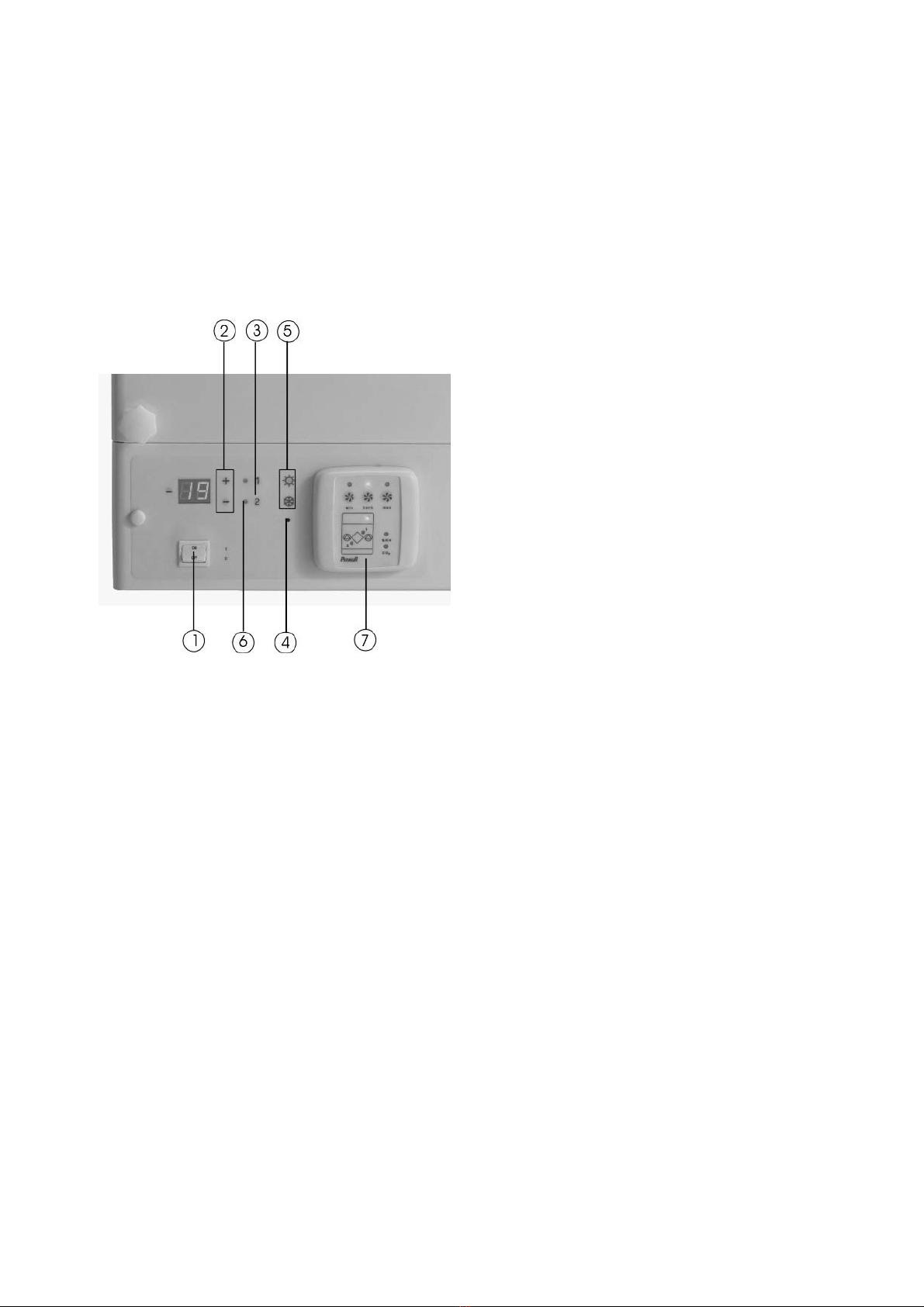
The Parmair Eximus Jr Units always come with a control unit. The control unit is attached to the
control panel of the unit, but it can also be detached and mounted on a switch case.
Another control unit (optional) can also be connected to the unit. The separate control unit will
function alongside the standard fixed control unit. The three fan speeds are set steplessly during
installation, and may be reconfigured at a later time (see the Implementation Guide).
The Parmair Eximus Jr Units can also be equipped with a control unit based on moisture (%RH),
carbon dioxide (CO2) or other outside control device such us a weekly timer. The unit
automatically switches to boosted ventilation when it receives an outside control voltage from
one of the mentioned sources; after the need for the boost is over, it returns to basic mode.
The ventilation unit should always at least be switched on to the lowest setting (min). This
will ensure that indoor air stays healthy and that the disadvantages of humidity and damage from
freezing are avoided.
6. INSTALLING THE UNIT
Parmair Eximus Jr Units are intended for installation in warm indoor areas (above +5°C). The
unit is attached to the wall by fixing points along the upper and lower edges and on the rear
panel of the unit. The unit should be tilted slightly backwards to allow the condensed water to
run out. A separate electric supply from distribution board is recommended for the unit.
7. CONNECTING THE CONDENSATION WATER PIPE
The condensation water pipe is laid separately to a floor drain, a drainpipe or a loose container.
To avoid airlocks, add water to seal when the unit has been installed and whenever maintenance
is performed on the filter.
THE CONDENSATION UNIT OF THE EXIMUS Jr UNIT IS ON THE BOTTOM OF THE
VENTILATION UNIT ON THE LEFT OR RIGHT SIDE, DEPENDING ON WHETHER IT IS
LEFT- OR RIGHT-HANDED.

8
PARMAIR EXIMUS JrS and JrV
8. INSTALLING THE DUCTS
There are four duct connections (∅160 mm) on the top of the unit (see Illustration 1 and 2).
1. Waste air 4. Extracted air
2. Fresh air 5. Water flow (Model JrV)
3. Incoming air 6. Water return (Model JrV)
RIGHT (R)
Illustration 1. Duct outlets (Right)
LEFT (L)
Illustration 2. Duct outlets (Left)

9
PARMAIR EXIMUS JrS and JrV
9. FUNCTIONS AND OPERATION OF UNIT
1. Master switch
2. Incoming air temperature control buttons
3. Reheating on/off button
4. Maintenance mode button
5. Summer/winter damper LEDs
6. Reheating element LED
7. Remote control unit (see Illustration 4)
Illustration 3. Control Panel
9.1 MASTER SWITCH
The master switch (1) is located on the lower part of the unit. The switch serves to cut off
electric power to the entire unit and the control unit.
(NB! If outside control units are attached to the unit, they have voltage regardless of the
position of the main switch.)
9.2 REHEATING TEMPERATURE CONTROL AND TEMPERATURE GAGE
The reheating element (Model JrS) or the water radiator control vent (Model JrV) will not be
switched on unless the temperature of the incoming air drops below the set temperature. The
temperature of incoming air can be controlled to the desired level (+10° C – +25° C) with the
“+” and “-” buttons (2) next to the LED display. The reheating on/off button (3) allows the
reheating resistor to be switched off.
Suitable incoming air temperature is usually approximately 2–3° C lower than the indoor air
temperature. Incoming air at too high a temperature reduces the efficiency of the ventilation.
Incoming air at too low a temperature can cause drafts.
The preheating element has no separate control and is automatically controlled when the
antifreeze function is switched on.

10
PARMAIR EXIMUS JrS and JrV
The Eximus Jr Unit has five temperature sensors that measure the following temperatures:
L1 Fresh air temperature before preheating
L2 Incoming air temperature to be blown into the house after reheating
L3 Extracted air temperature before heat exchanger
L4 Waste air temperature after heat exchanger
L5 Temperature of the coldest spot on the heat exchanger
The measured temperatures are shown on the display on the front panel. The temperature
displays can be accessed by pushing the “+” and “-” buttons simultaneously. The panel first
displays the code of the sensor (L1, L2…), and two seconds later the temperature measured by
the sensor. The sensor code and temperature are shown at two-second intervals on the display.
The “+” button displays the temperature of the next measured point. If no button is pushed for
10 seconds, the display returns to basic mode.
9.3 MAINTENANCE MODE BUTTON
The concealed maintenance mode button (4) is used for presetting the fan speeds
(see Implementation Guide).
9.4 SUMMER/WINTER DAMPER LED
The summer/winter damper LED (5) tells you whether the heat recovery bypass dampers are
down for the summer or up for the winter. The damper LED is controlled using the switch inside
the unit.

11
PARMAIR EXIMUS JrS and JrV
8. Normal ventilation (Norm)
9. Reduced ventilation (Min)
10. Boosted ventilation (Max)
11. Preheating LED (1)
Reheating LED (2)
12. Maintenance monitor LED
13. %RH control LED
14. CO2control LED
Illustration 4. Remote Control Unit
9.5 CHOOSING VENTILATION EFFECT
The preset ventilation settings can be saved so that they can be operated with three buttons.
Normal ventilation (8) is recommended for continuous use. Reduced ventilation (9) is
recommended when the house is going to be vacant for several days or when the temperature
falls well below zero. When necessary, boosted ventilation is selected by pushing button (10).
9.6 LEDS
The reheating LED (6) shows a green light when the reheating element is turned on with the
on/off switch. The LED on the remote control unit (11) shows a yellow light when the element is
heating the incoming air.
A red light on the maintenance monitor LED (12) means that the unit requires maintenance
(cleaning or changing of the filter, cleaning of the heat exchanger). When the maintenance
monitor LED (12) and the reheating LED (11) blink simultaneously, this may indicate that the
frost protection function is turning on. The frost protection control is turned on when the intake
air temperature falls to +8°C or below. The maintenance monitor LED (11) can occasionally
blink a red light. This means that the unit is testing its own functions and does not require any
measures. The indoor moisture %RH LED (13) or the carbon dioxide CO2LED (14) are lit when
the ventilation is boosted due to control based on either one of these sensors (optional).

12
PARMAIR EXIMUS JrS and JrV
When the maintenance monitor led (12) and the fan speed symbol blink simultaneously, the fan
is malfunctioning. The function may be activated when the antifreeze function is working and
the unit is slowing the intake fan down. The function also turns on when a fan malfunctions.
9.7 THERMAL SHIELD
Both of the unit’s heating elements are equipped with a resettable thermal shield. If the thermal
shield has been tripped, it can be reset by pushing the reset button. The set value of the manual
thermal shield is +70° C. The set value of the thermal shield with automatic reset function is
+40° C.
(NB! The cause of the tripping of the thermal shield with the reset function must always be
clarified.)
10. MAINTENANCE
In order to ensure the faultless performance of the Eximus Jr Unit under all conditions, it is
important to service the unit at regular intervals. Maintenance is limited in practice to cleaning
the air filters, heat exchanger, fans and internal parts. It is recommended that maintenance
operations be performed in the following order:
NB! Be sure there is no current in the unit before doing any maintenance work.
a) CLEANING THE HEAT EXCHANGER
Remove knobs and lift front cover away from unit. Beware of hot surfaces!
Remove any dirt adhering to heat exchanger (approximately every second year) in order for it to
work efficiently. The heat exchanger can be removed from the unit by carefully withdrawing it.
NB! Beware of the heat exchanger’s sharp edges when removing and handling it.
Wash heat exchanger in hot water, for example by using a hand-held spray.
Clean interior of unit, if necessary.

13
PARMAIR EXIMUS JrS and JrV
b) SUMMER/WINTER DAMPER
The Eximus Jr Units are equipped with a summer/winter damper. In summer, when it is not
necessary to preheat incoming air by means of extracted air, the damper should be placed on top
of the heat exchanger and the winter/summer switch should be switched in the down position. In
cooler autumn weather, the damper should be removed and the switch placed in the up position.
The LED (5) indicates the position of the summer/winter dampers when the summer/winter
switch is in the correct position.
Damper 1
Damper 2
c) CLEANING FILTERS
It is recommended that filters be cleaned at four-month intervals. The exhaust filter can be
cleaned by vacuuming or knocking it gently. The filter tolerates 3–4 cleanings. The incoming air
filter can be vacuumed from the side on which the dust collects. Filters should be replaced each
year in order to maintain efficiency. The cleaning and replacing should be confirmed by pushing
the green reset button on top of the fans twice. In order for the unit to register the push of the
reset button, power must be turned on.
If the fans have become very dirty or almost not dirty at all during the four months the setting of
the maintenance monitor can be changed. Push the maintenance button in the filter compartment
once. The unit now displays the standard setting “04” that can be changed by pushing the “+”
and “-” buttons.
d) CLEANING FANS
Both fans can be cleaned, if necessary. Fans can be manually removed without any tools. First
unplug the unit. Open the cover of the unit, remove heat exchanger and loosen fan connectors
and fixing screws. Carefully remove fan and hood. Dirt on the fan blades can be removed by
brushing with care.
Maintenance work involving opening the control panel should only be performed by a
qualified electrician.

14
PARMAIR EXIMUS JrS and JrV
PARMAIR EXIMUS Jr VENTILATION UNITS – IMPLEMENTATION
GUIDE
General
The Parmair Eximus Jr Unit is designed for easy-to-use ventilation for houses, clubhouses,
business premises, etc. In order to ensure proper functionality of the unit, the following
preparations should be performed by a qualified installer. The following settings may be
reconfigured by the installer:
- Normal speed of extract fan (min–max)
- Reduced speed of extract fan (20–norm)
- Boosted speed of extract fan (norm–100)
- Difference - extract and intake fan effect (-30%–0%)
The speed settings are configured in the maintenance mode display, which is accessed by
pushing the maintenance mode button (4) on the front edge of the unit once using e.g. the tip of a
pen. The settings in the maintenance mode display can be browsed with the heating element
on/off buttons (3). The settings are changed by pushing the “+” and “-” buttons (2). The display
will return to the basic mode when the maintenance mode button is pushed again.
Illustration 5. Control panel

15
PARMAIR EXIMUS JrS and JrV
Air exchange volume flow
The air volume of the Eximus Jr Unit can be determined with the aid of the following chart
based on the rotation speed of the fans (e.g. set value 60=80l/s).
Eximus Jr 140 flow rates (100 Pa)
0
20
40
60
80
100
20
40
60
80
100
120
140
Flow rate (l/s)
Set value [Pa]
Extract
Supply
Reduced supply air 0 -30 %
Chart 1. Set value/air volume curve with 100 Pa pressure loss
Setting the ventilation effect
During installation of the unit, a qualified installer can set the extract fan rotation speed to
normal (norm), reduced (min) or boosted (max) ventilation. The setting is done as follows:
- Push the normal speed button (button 8, Illustration 4)
- Push the maintenance mode button (button 4) once so that code P1 is shown on
the display.
- Select normal fan power with the “+” and “-” buttons (factory setting is 50)
- Push the reduced speed button (button 9, Illustration 4)
- Push the heating element on/off button (button 3) until code P3 is shown on the
display.
- Push the “+” or “-” buttons until the desired reduced setting is displayed (factory
setting 25)
- Push the boosted speed button (button 10, Illustration 4)
- Push the heating element on/off button (button 3) until code P4 is shown on the
display.
- Push the “+” or “-” buttons until the desired boosted setting is displayed (factory
setting 90)

16
PARMAIR EXIMUS JrS and JrV
The minimum speed is always lower and the boosted speed greater than normal speed. When the
speed is changed in any mode other than the maintenance mode, the rotation speed of the
Eximus Jr Unit will change within one minute.
Setting the extract and intake fan rotation ratio
In order to create an underpressure in the house, the rotation ratio of the intake and extract fans
must be adjusted. This is done as follows:
- Push the maintenance mode button (button 4.)
- Push the heating element on/off button (button 3) until code P2 is shown on the
display.
- Push the “+” or “-” buttons until the desired fan rotation ratio is between -30%
and 0% (the factory setting is -20%).
Setting and resetting the maintenance monitor time
The time of the maintenance monitor can be changed when the unit is being installed by pushing
the filter-reset button once. The display now shows the set time. The desired time can be set with
the “+” and “-” buttons. The maintenance monitor time can be set to 2–12 months with one-
month intervals. The factory setting is four months. If no button is pushed within 10 seconds, the
display returns to the basic mode.
After the filter has been cleaned or changed, the maintenance monitor must be reset by pushing
the reset button in the filter compartment twice. The unit must be running when the reset button
is pushed, otherwise the action will not be saved in the memory of the unit.

17
PARMAIR EXIMUS JrS and JrV
Malfunction indicators
The control card of the Eximus Jr Unit can detect the following malfunctions:
- Intake fan not working properly
- Extract fan not working properly
When the unit malfunctions, the maintenance monitor LED on the remote control unit (12
Illustration 4) blinks red. If the triak abbreviation of the heating element has short circuited, the
element power is automatically switched off until the unit is switched on again.
In order to resume, the unit must be reset by switching the power of the unit off, then repairing
the damage or exchanging the faulty component. When power is switched back on, the
malfunction indicator will be turned off. If the repair measure was incorrect, the malfunction
indication will be repeated.
Installing a second remote control unit
The Parmair Eximus Jr is controlled with the control unit on the front panel of the unit. The
control unit attached to the unit can also be detached and mounted on a suitable place. If another
remote control is needed, the cable should be attached to the four-pin port on the front edge of
the control card. 3 x 2 x 0.5 mm or 2 x (2+1) x 0.5 mm cables should be used for the installation.
Then turn switch number 1 on the DIP-switch on the remote control unit to the down position.
Restoring factory settings
The original factory settings can be restored. This is done by switching the unit on from the main
switch and simultaneously pushing the maintenance mode button. The display shows the text
“CL”. Release the maintenance mode button and push it again. The factory settings are now
restored.

18
PARMAIR EXIMUS JrS and JrV
Basic display, temperature
Of air blown into the house
Temperature adjustment,
Temperature setting of air blown into the house
Basic display
Push the plus Set new incoming Returns to basic display
or minus button air temperature after 10 seconds
The temperatures measured by all the temperatures of the ventilator may be viewed. The
temperature display mode may be accessed by pushing the ’’+’’ and ’’-’’ buttons
simultaneously. In the temperature display mode, the measuring sensor is changed by pushing
the ’’+’’ and ’’-’’ buttons. The display automatically returns to the basic display 10 seconds after
the last push of button.
1st Temperature 2nd Temperature
Basic display Fresh air temperature Incoming air temperature
Display changes Display changes
Every second every second
3rd Temperature 4th Temperature
Extract air temperature Waste air temperature
Display changes Display changes
Every second every second
5th Temperature
Heat exchanger temperature
Display changes
Every second

19
PARMAIR EXIMUS JrS and JrV
Maintenance mode
The fan speed of the unit can be adjusted in the maintenance mode. The maintenance mode is
accessed by pushing the concealed maintenance button. In the maintenance mode, the display
shows the current adjustment parameter value, which can be changed. The parameter setting is
changed by pushing the ’’+’’ and ’’-’’ buttons, and the parameter to set is changed by pushing
heating element control buttons 1 and 2. The maintenance mode is switched off by pushing the
maintenance mode button again.
P1 Adjustment P1 Adjustment
Basic display Extract air normal speed (norm) Extract air normal speed
Push the The value is displayed
maintenance in 2 seconds
mode button
P2 Adjustment P2 Adjustment
Intake/extract air ratio Intake/extract air ratio
The value is displayed
in 2 seconds
P3 Adjustment P4 Adjustment
Extract air reduced speed (min) Extract air boosted speed (max)
The value is displayed The value is displayed
in 2seconds in 2 seconds
Restoring the factory settings
If the settings were not successfully changed, the factory settings can be restored. This is done
by holding the maintenance mode button down while the unit is initializing. When the display
shows the text ’’CL’’, push the maintenance button again.
Initializing display Restoring the factory settings Basic display
Push the Push the Factory settings
maintenance mode maintenance mode restored
button button

20
PARMAIR EXIMUS JrS and JrV
Maintenance monitor
The working period of the maintenance monitor of the ventilation unit can be adjusted. The
setting is done by pushing the maintenance reset button. The display now shows the set working
period of the maintenance monitor. The time can be changed by pushing the ’’+’’ and ’’-’’
buttons. The maintenance monitor is reset by pushing the maintenance rest button twice.
Setting the maintenance monitor working period.
Basic display Previous setting New setting
Push the maintenance Set new time Returns to basic display
reset button in 10 seconds
Resetting the maintenance monitor:
Previous maintenance Maintenance monitor
Basic display monitor setting reset
Push the Push the Returns the basic display
maintenance maintenance in 2 seconds
reset button reset button again
This manual suits for next models
1
Table of contents
Popular Fan manuals by other brands

TREVIDEA
TREVIDEA G3FERRARI MARINO G50035 user manual

Carlton
Carlton FW6D Instruction book

Casablanca
Casablanca 19 Century owner's manual

Anslut
Anslut 014274 operating instructions

Omega Altise
Omega Altise OHVP40C instruction manual

Home Decorators Collection
Home Decorators Collection 68-ATRDC Use and care guide

Chillout
Chillout GF60XE Series operating instructions

Hapton Bay
Hapton Bay MARLOWE Use and care guide

Ebmpapst
Ebmpapst G2E120-FC80-01 operating instructions

Ebmpapst
Ebmpapst R2E250-RA50-01 operating instructions

Air King
Air King 9312 Operating instructions and parts manual

System air
System air IF Q installation manual