4878 Automated Liquid Sampler
www.parrinst.com 3
PREFACE
Scope
These instructions cover the installation and op-
eration of the Parr 4878 Automated Liquid Sampler
as used with Parr Laboratory Reactors and Pres-
sure Vessels.The users should study the instruc-
tions carefully before using these instruments so
that they will fully understand the capabilities of
this equipment and the safety precautions to be
observed in its operation.
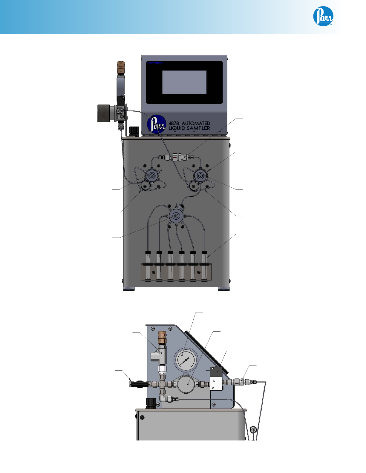
Applications
The Parr 4878 Automated Liquid Sampler is
designed specifically for use with Parr reactors
and pressure vessels. The sampler system can
be used with reactors from any manufacturer
provided the vessel is equipped with a dip tube
arrangement as is provided as a standard feature
in reactors from Parr. This dip tube extends down
to nearly the inside bottom of the vessel and
typically connects to two valves on the top of the
head.The upper valve is used as a gas inlet valve,
and the lower of the two valves is used as the
liquid sampling valve.
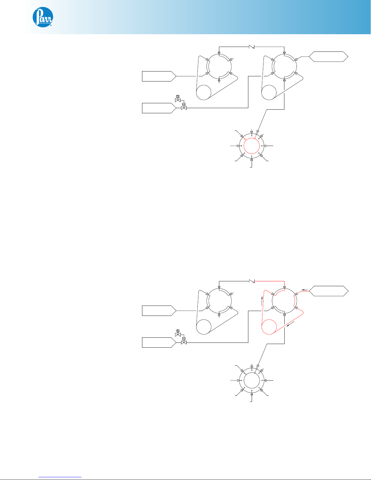
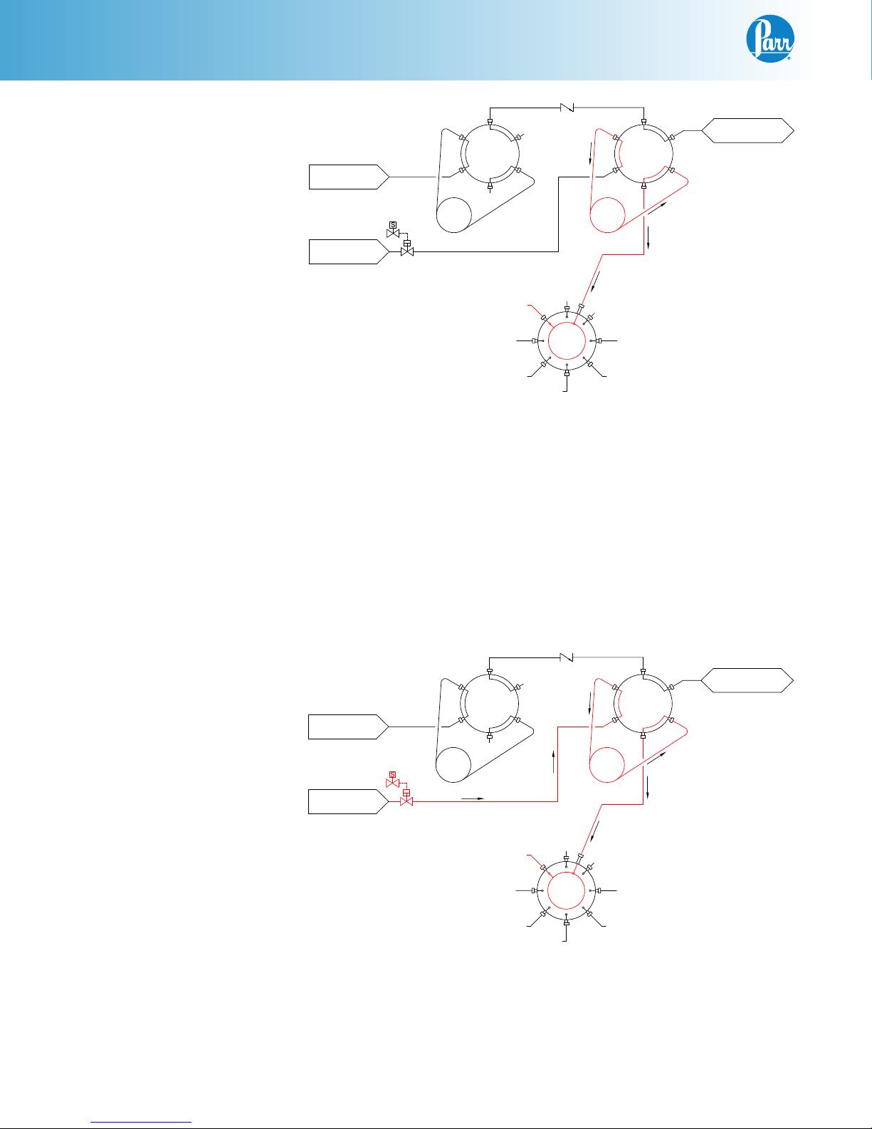
To ensure that the second and subsequent samples
are fresh and indicative of current reactor contents,
it is prudent to first allow some gas to enter the re-
actor pushing the liquid remaining in the dip tube
from the previous sampling back into the reactor.
As you will see shortly, this Liquid Sampler has
features that allow this function to be automated.
Intended Usage
This instrument has been designed, built, and
tested to strict physical and electrical standards.
However, it is the user’s responsibility to install
and operate it in conformance with local pressure
and electrical codes.
If the instrument is used in a manner not speci-
fied by Parr Instrument Company, the protection
provided by the equipment may be impaired.
Establish training procedures to ensure that any
person handling the equipment knows how to use
it properly.
Related Instructions
The following Parr publications are also included
to further your understanding of this instrument
and its component parts:
No. Description
201M Limited Warranty
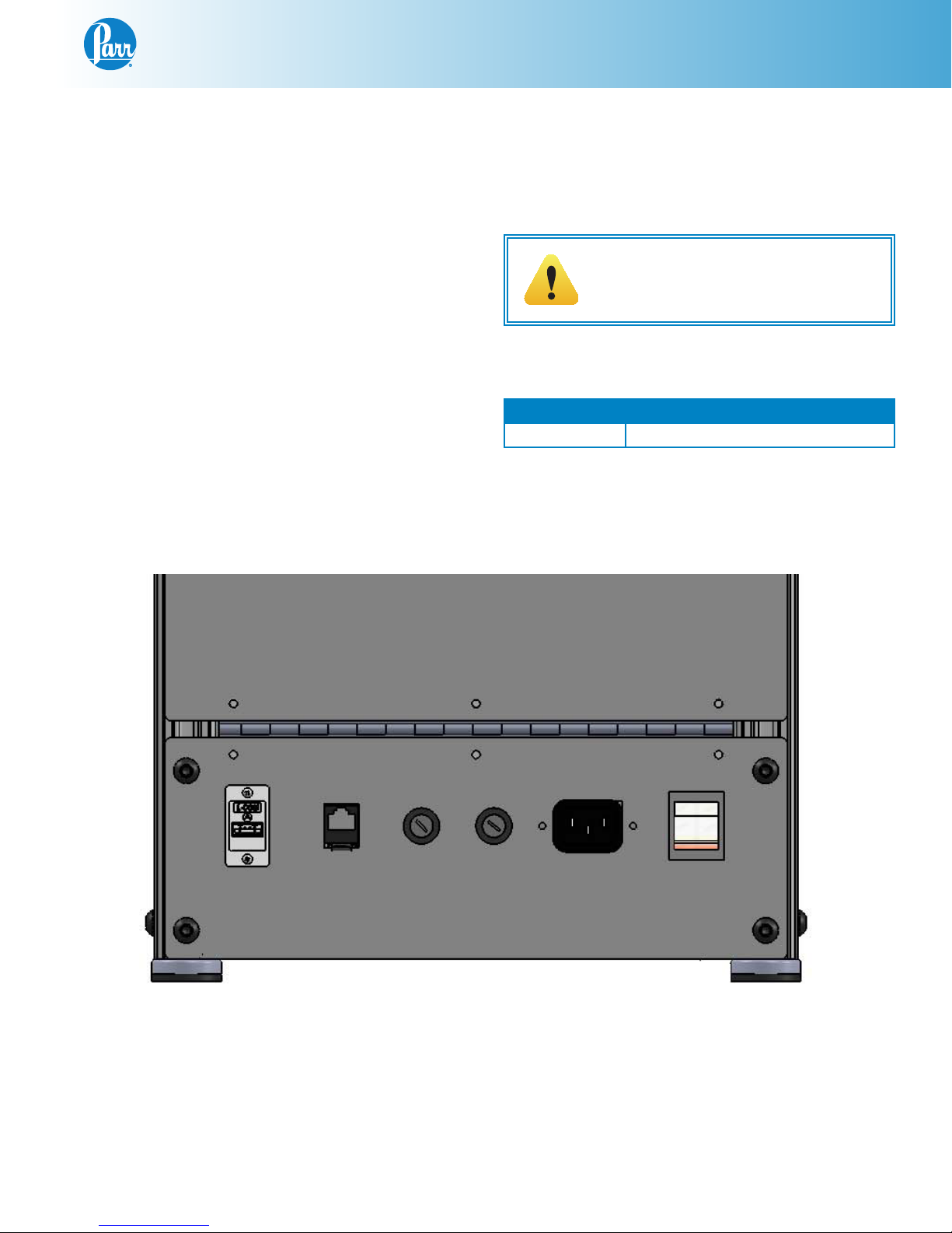
Explanation of Symbols
I On position
O Off Position
~ Alternating Current (AC)
This CAUTION symbol may be present
on the Product Instrumentation and
literature. If present on the product,
the user must consult the appropriate
part of the accompanying product
literature for more information.
Protective Earth (PE) terminal.
Provided for connection of the
protective earth (green or green/
yellow) supply system conductor.
Safety Information
To avoid electrical shock, always:
1. Use a properly grounded electrical outlet of
correct voltage and current handling capability.
2. Ensure that the equipment is connected to
electrical service according to local national
electrical codes. Failure to properly connect
may create a fire or shock hazard.
3. For continued protection against possible
hazard, replace fuses with same type and
rating of fuse.
4. Disconnect from the power supply before
maintenance or servicing.
To avoid personal injury:
1. Do not use in the presence of flammable or
combustible materials; fire or explosion may
result.This device contains components which
may ignite such material.
2. Refer servicing to qualified personnel.