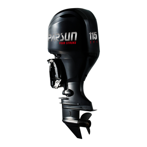
Parsun F115 BEX-T User manual

Service Manual
F115/FL115
Suzhou Parsun Power Machine Co., Ltd.

Preface
This Manual includes the maintenance instruction for F115 and FL115 outboard motors,
which is provided by Parsun to dealers for use in maintaining and repairing Parsun outboard motors.
Please read this Manual carefully before maintaining and servicing the outboard motors. When
repairing and maintaining the outboard motors, please use the maintenance procedures and tools
recommended in the Manual.
If you choose other maintenance procedures and tools, please follow the instructions of
experienced maintenance personnel to avoid injuries to personnel and the outboard motor.
The materials, drawings and technical parameters used in this Manual are based on the
prototype at the time of publication, so there may be some small differences between the actual motor
you purchased and that described in the Manual; If necessary, our Company will distribute the revised
part to the dealers in various places.
When the following characters appear in this Manual, please read the Manual carefully
and execute the relevant instructions and descriptions correctly and carefully.
Warning:
Failure to comply with the warnings may lead to injury to maintenance personnel and
bystanders, and severe cases may result in death.
Note:
“Note” means that preventive measures must be taken to avoid damage to the outboard
motor.
Note:
Key information are provided to make your operation steps simpler and clearer.
The last part of this Manual describes the common faults and troubleshooting methods of
the outboard motor. Please read it carefully; When overhauling the outboard motor, it can help
you quickly judge the status of the motor and improve working efficiency.
It is forbidden to copy and disseminate this Manual without written authorization
Suzhou Parsun Power Machine Co., Ltd.

Contents
Overview ................................................................................................................................................. 1
Identification mark .................................................................................................................................. 1
Selection of propeller .............................................................................................................................. 1
Protection at work ................................................................................................................................... 2
Disassembly and assembly ..................................................................................................................... 3
Disposable parts ...................................................................................................................................... 3
Pre-delivery inspection ........................................................................................................................... 3
Special tools and testing equipment ........................................................................................................ 5
Disassembly schematic diagram and symbol description ....................................................................... 7
Description of disassembly schematic diagram .............................................................................. 7
Symbol description ......................................................................................................................... 7
Specification ........................................................................................................................................... 8
Outboard motor parameters ............................................................................................................ 8
Maintenance information ........................................................................................................................ 9
Engine ............................................................................................................................................. 9
Underwater unit ............................................................................................................................ 10
Electrical system ........................................................................................................................... 11
Seating torque ....................................................................................................................................... 12
Specified torque ............................................................................................................................ 12
Average torque .............................................................................................................................. 13
Overall dimensions ............................................................................................................................... 14
Basic maintenance ................................................................................................................................ 19
Maintenance Interval Chart ................................................................................................................... 19
Fuel system ........................................................................................................................................... 20
Engine ................................................................................................................................................... 20
Engine oil level ............................................................................................................................. 20
Change engine oil ......................................................................................................................... 21
Spark plug ..................................................................................................................................... 21
Control system ...................................................................................................................................... 22
Throttle push-pull cable ................................................................................................................ 22
Shift operation ............................................................................................................................... 22
Underwater unit .................................................................................................................................... 23
Gear oil .......................................................................................................................................... 23
Replace gear oil ............................................................................................................................. 23
Air tightness inspection of underwater unit .................................................................................. 23
General maintenance ............................................................................................................................. 24
Anode ............................................................................................................................................ 24
Lubricating point ........................................................................................................................... 24
Cooling water channel .................................................................................................................. 24
Thermostat .................................................................................................................................... 25
Propeller ........................................................................................................................................ 25
Check the main switch/stop switch ............................................................................................... 25
Change the oil filter ...................................................................................................................... 26
Check the top cover ...................................................................................................................... 26
Check valve clearance ................................................................................................................... 27
Electrical system ................................................................................................................................... 28
Matters needing attention ...................................................................................................................... 28
Disassembly schematic diagram ........................................................................................................... 29

Wiring diagram ..................................................................................................................................... 35
Spark plug ignition ................................................................................................................................ 37
Spark plug cap ....................................................................................................................................... 37
Flywheel maintenance .......................................................................................................................... 37
Ignition coil detection ........................................................................................................................... 37
Trigger coil detection ............................................................................................................................ 37
Check engine startup switch ................................................................................................................. 38
Check engine stop switch ...................................................................................................................... 38
Detection of starting relay ..................................................................................................................... 38
Detection of magneto coil ..................................................................................................................... 38
Detection of rectifier regulator .............................................................................................................. 38
Use fault diagnosis tester ...................................................................................................................... 39
Fault code table ............................................................................................................................. 39
Fuel system ........................................................................................................................................... 41
Matters needing attention ...................................................................................................................... 41
Disassembly schematic diagram ........................................................................................................... 42
Reduce fuel pressure ............................................................................................................................. 50
Check the oil filter cup .......................................................................................................................... 50
Removal and inspection of fuel pump .................................................................................................. 50
Check the fuel filter .............................................................................................................................. 51
Remove and check the fuel injector ...................................................................................................... 51
Check throttle body ............................................................................................................................... 52
Check the intake manifold .................................................................................................................... 52
Disassemble and check the carbon canister and carbon canister solenoid valve .................................. 52
Disassemble and check the electric fuel pump ..................................................................................... 53
Engine ................................................................................................................................................... 54
Matters needing attention ...................................................................................................................... 54
Disassembly schematic diagram ........................................................................................................... 55
Special tool ............................................................................................................................................ 67
Check the compression pressure ........................................................................................................... 67
Check oil pressure ................................................................................................................................. 67
Check valve clearance ........................................................................................................................... 68
Adjust valve clearance .......................................................................................................................... 71
Remove the engine ................................................................................................................................ 72
Pulley and timing belt ........................................................................................................................... 73
Disassembly and inspection .................................................................................................................. 73
Cylinder cover ............................................................................................................................... 73
Check the valve tappet .................................................................................................................. 73
Check the driven pulley ................................................................................................................ 74
Check the cylinder head bolts ....................................................................................................... 74
Valve and valve guide ................................................................................................................... 74
Valve spring .................................................................................................................................. 74
Replace valve guide ...................................................................................................................... 75
Check valve seat ring .................................................................................................................... 75
Trim the valve seat ring ................................................................................................................ 75
Assemble and mount the cylinder head ........................................................................................ 76
Crankcase .............................................................................................................................................. 77
Disassembly .................................................................................................................................. 77
Piston ............................................................................................................................................. 78
Cylinder bore ................................................................................................................................ 78

Outside diameter of piston pin ...................................................................................................... 78

Piston ring ..................................................................................................................................... 78
Inner diameter of connecting rod small end ................................................................................. 79
Inner diameter of connecting rod large end .................................................................................. 79
Connecting rod large end backlash ............................................................................................... 79
Crankshaft ..................................................................................................................................... 79
Crank pin oil clearance ................................................................................................................. 80
Selection of connecting rod bearing bush ..................................................................................... 80
Main journal oil clearance ............................................................................................................ 81
Selection of crankshaft bearing bush ............................................................................................ 81
Body and engine base ................................................................................................................... 82
Check the oil pump ....................................................................................................................... 82
Check and mount exhaust pipe ..................................................................................................... 82
Reinstallation ........................................................................................................................................ 83
Assemble piston connecting rod ................................................................................................... 83
Installing the piston rings .............................................................................................................. 83
Installing piston ............................................................................................................................. 83
About water ........................................................................................................................................... 85
Top cover............................................................................................................................................... 85
Disassembly schematic diagram ................................................................................................... 85
Disassembly and inspection .......................................................................................................... 87
Bottom cover ......................................................................................................................................... 88
Disassembly schematic diagram ................................................................................................... 88
Disassembly and inspection .......................................................................................................... 92
Water unit and bracket .......................................................................................................................... 93
Disassembly schematic diagram ................................................................................................... 93
Disassembly and inspection of bracket ......................................................................................... 99
Disassembly and inspection of water unit .................................................................................... 99
Hydraulic warping device ................................................................................................................... 100
Check the oil level. ..................................................................................................................... 100
Underwater part .................................................................................................................................. 102
Disassembly schematic diagram ......................................................................................................... 102
Disassembly and inspection ................................................................................................................ 113
Propeller shaft and clutch block .................................................................................................. 114
Install the claw clutch ................................................................................................................. 114
Housing cover of underwater unit ............................................................................................... 114
Install the oil seal and bearing of the housing cover ................................................................... 114
Drive shaft ................................................................................................................................... 115
Shift cam ..................................................................................................................................... 115
Gear ............................................................................................................................................. 115
Forward gear bearing .................................................................................................................. 115
Check the housing of the underwater unit .................................................................................. 115
Check the water pipe ................................................................................................................... 115
Assemble underwater unit ................................................................................................................... 115
Install the underwater unit .................................................................................................................. 117
Selection of shim ................................................................................................................................. 118
Deviation value mark .................................................................................................................. 119
Pinion shim ................................................................................................................................. 120
Forward gear shim ...................................................................................................................... 120
Reverse gear shim ....................................................................................................................... 121

Backward-rotating pinion shim ................................................................................................... 122
Propeller shaft shim .................................................................................................................... 122
Reverse gear shim ....................................................................................................................... 123
Forward gear shim ...................................................................................................................... 123
Common faults and solutions .............................................................................................................. 124

1
Overview
Identification mark
The serial number is printed on a label which is pasted on the port side of the clamp bracket
or the upper part of the rotary bracket. The serial number is recorded in the blank of the label to help
you order spare parts from dealers or for your reference in case the engine is stolen.
1. Position of the serial number
The numbers are expressed as follows:
发动机顺序号
SN
生产代号
Selection of propeller
The performance of the outboard motor is seriously affected by the propeller. Improper
selection will have adverse effects on the motor. When the ship runs in full load, the motor will
operate at low speed for a long time. At this time, the propeller with smaller pitch should be selected,
whereas the propeller with larger pitch should be selected to maintain the normal operation of the
engine.
When the engine is running at full throttle, the most suitable propeller for the ship is to refer
to the engine speed and fuel performance, which can provide the highest performance.
Propeller dimensions Material
3-14"×11" Aluminum alloy
3-13 "
8
5×13" Aluminum alloy
3-13 "
8
5×14" Aluminum alloy
3-13 "
2
1×15" Aluminum alloy
3-13 "
4
1×17" Aluminum alloy
3-13"×19" Aluminum alloy
3-12 "
8
5×21" Aluminum alloy
3-13"×23" Aluminum alloy
3-13"×25" Aluminum alloy
3-13 "
2
1×14" Stainless steel
1

2
Continued:
Propeller dimensions Material
3-13 "
2
1×16" Stainless steel
3-13"×17" Stainless steel
3-13"×19" Stainless steel
3-13"×21" Stainless steel
3-13"×23" Stainless steel
3-13"×25" Stainless steel
3-13 "
2
1×17" Stainless steel
3-13 "
2
1×19" Stainless steel
3-13 "
2
1×21" Stainless steel
3-12 "
2
1×23" Stainless steel
3-13"×17" Stainless steel
Backward-rotating propeller:
Propeller dimensions Material
3-13"×17" Stainless steel
3-13"×19" Stainless steel
3-13"×21" Stainless steel
Note:
Backward-rotating outboard motor must use backward-rotating propeller,
otherwise the vessel will not advance in the desired direction, which is likely to cause accidents!
Protection at work
In order to prevent danger or accident during maintenance and improve work quality, please
observe the following safety regulations.
1. Fire prevention
Gasoline and various lubricating oils and greases are easy to burn; Keep away from heat
sources, sparks and open flames during operation.
2. Ventilation
Gasoline vapor and engine exhaust gas are highly toxic. Massive inhalation of such
substances can cause shock and even death. When testing the engine indoors, please keep
good ventilation conditions.
3. Self-protection
Wear protective glasses when drilling, grinding or using air compressors. Wear

3
protective gloves and safety shoes when necessary.
4. Use of lubricants and sealants
Only products provided or recommended by Parsun can be used when maintaining and
repairing the outboard motor.
Under normal circumstances, the lubricant mentioned in this Manual will not damage
your skin. However, please take protective measures before use to reduce risks.
○
1 Apply protective cream on both hands before overhauling the outboard motor;
○
2 Replace and clean the clothes as soon as possible after they are contaminated by the
lubricant;
○
3 Avoid skin contact;
○
4 Wash your hands and skin carefully with soap and hot water after contact with the
lubricant;
○
5 Wipe the spilled grease with a clean, lint-free rag.
5. Develop good work habits
○
1 Tighten nuts, bolts and screws according to the specified torque from large size to
small size, from the center to the outside.
○
2 Use recommended special tools to avoid damage to parts. Use the right tools in the
proper way.
Disassembly and assembly
When disassembling and assembling the outboard motor, please follow the following
principles:
1. Please use special tools when disassembling and assembling the parts of the outboard
motor;
2. Remove dust and dirt before decomposing the parts;
3. Apply engine oil on the contact surface of moving parts before assembly;
4. When installing the bearing, place the manufacturer's mark in the specified direction and
fully lubricate it;
5. Before installation, coat a thin layer of waterproof lubricating oil on the protruding part
and periphery of the oil seal;
6. After assembly, check whether the moving parts work normally.
7.
Disposable parts
Parts such as gasket, oil seal, O-ring, cotter pin and spring ring are disposable parts, and they
must be replaced before reinstalling the outboard motor.
Pre-delivery inspection
To ensure the normal use by customers, please carry out the following inspection before
delivery. 1. Check the fuel system.
Check whether the fuel hose is securely connected and whether the fuel tank is full.
Note:
As it is a four-stroke engine, premixed fuel cannot be used.
2. Check the oil level.
3.
○
1 Check engine oil level.
Pull out the oil dipstick and observe the oil level through the dipstick.

4
1. Oil dipstick 2. High mark 3. Low mark
Make sure the oil level is between the high mark and the low mark; Drain oil when the
oil level is above the high mark and add oil when the oil level is below the low mark.
○
2 Check gear oil level
Unscrew the oil level plug and observe whether the oil overflows in the oil level plug.
If yes, install the oil level plug and tighten it according to the specified torque; If not, fill
it with oil.
1. Oil level plug
3. Check the steering system.
Check whether the steering is smooth;
Check whether the steering friction is adjusted correctly.
Turn the locking bolt clockwise to increase the resistance.
Turn the locking bolt counterclockwise to reduce the resistance.
4. Check shift and throttle operation.
Check whether the shift operation is smooth; Check whether the throttle grip operates
smoothly from the full-close position to the full-open position.
5. Check the emergency stop switch assembly.
Check whether the engine stops when the emergency stop switch assembly is pressed
and hold or the engine stop safety line is pulled out.
6. Check the cooling water peep door.
When the engine is running, check whether the cooling water flows out of the cooling
water observation hole.
1. Cooling water observation hole
7. Running-in operation.
○
11st hour: The engine runs at 2000 rpm or about half of the throttle.
②2nd hour: Run the engine at 3000 rpm or about 3/4 of the throttle.
③The next 8 hours: Avoid running at full throttle for 5 minutes continuously.
8. Inspection after running-in operation
○
1Check the gear oil for water.
②Check the fuel line for leaks.
③After running-in operation, run the engine at idle speed and use the washing tool to
flush the cooling water channel with fresh water.
1
1
1
2
2
2
3

5
Special tools and testing equipment
Various special tools and testing equipment will be used when repairing and maintaining the
outboard motor. Using these tools and equipment expertly and correctly can improve your work
efficiency and effectively avoid injuries to personnel and the outboard motor.
Special tools:
Clearance gauge Piston slideway Flywheel gripper and flywheel puller
Oil filter spanner
Bearing puller underwater
unit housing cover
Needle bearing
installation tool
Underwater unit
housing cover bearing
installation tool
Underwater unit
housing cover oil
seal installation tool
Underwater unit needle
bearing installation tool
Drive shaft bearing
jacket installation tool
Drive shaft bearing
installation tool
Drive shaft seal oil
seal installation kit
Forward gear bearing
casing installation kit

6
Drive shaft spline sleeve pinion nut spanner
Testing equipment:
Digital tachometer Digital multimeter Peak voltage adapter

7
Disassembly schematic diagram and symbol description
Description of disassembly schematic diagram
③
②
①
④
M10x1.5x105 mm
1st 16 Nm
2nd 42 Nm
M8x55 mm
1st 14 Nm
2nd 28 Nm
49 Nm
18 Nm
①Exploded view of parts.
②Thread specification and specified torque.
③Points where oil, sealant or locking agent are applied
④Parts list.
Symbol description
O G
L
1277
GM
Apply engine oil Apply waterproof
grease
Apply thread
locker 1277
Apply thread locker
1243 Apply sealant

8
Specification
Outboard motor parameters
Item Data Item Data
Overall
dimensions
Full length 833 mm
Engine
Ignition
system TCI
Overall width 517 mm
Spark plug LKR6E
Overall
height
L-type 1672 mm
X-type 1799 mm Exhaust
system Through the propeller hub
Stem
board
Height
L-type 510 mm Lubrication
system Purging-type oil mist lubrication
X-type 637 mm
Fuel
and oil
Fuel type Regular unleaded petrol
Weight
L-type 175kg Fuel grade PON86
X-type 179kg Recommended
engine oil grade
API: SE, SF, SG,SH, SJ
SAE: 10W30, 10W40
Performance
Maximum output 85Kw@5600r/min Engine oil level
Total 3.8L
Do not change the
oil filter 3.0L
Change the oil
filter 3.2L
Full throttle
operating range 5300~6300 r/min Recommended
gear oil Hypoid gear oil SAE﹟90
Maximum fuel
consumption
38.9L/h@5600
r/min Gear oil level Forward-rotating 0.760L
Backward-rotating 0.715L
Idle (neutral
position) 800~900r/min
Bracket
Inclined rising
angle (degree) 70
Engine
Type 4-stroke, DOHC
L4, 16 valves
Number of
cylinders 4 Steering angle
(degree) 35+35
Displacement 1832cm³
Drive
Device
Gear F-N-R
Cylinder bore ×
stroke 81.0mm×88.9mm Transmission
ratio 2.15
Compression
ratio 10:1 Gear type Spiral bevel gear
Minimum
compression
pressure
945kPa Clutch type Claw clutch
Lubricating oil
pressure
440kPa (at idle
speed)
Propeller shaft
type Spline
Propeller
direction
Forward-rotating Clockwise (rear
view)
Control system
Remote
control/steering
handle
Backward-rotating Counterclockwise
(rear view)
Start-up system Electric starting

9
Maintenance information
Engine
Item Data Item Data
Cylinder cover Warping limit 0.1mm Valve Edge
thickness
Intake valve 0.8~1.2mm
Inner diameter of
camshaft
25.000~25.021m
m
Exhaust
valve
1.0~1.4mm
Camshaft oil clearance 0.020~0.061mm Stem
diameter
Intake valve 5.475~5.490mm
Oil clearance limit 0.080mm Exhaust
valve
5.460~5.475mm
Cylinder block Cylinder bore 81.00~81.012mm Inner
diameter
of valve
guide
5.504~5.522 mm
Wear limit 81.061mm Clearance
between
guide and
valve stem
Intake valve 0.014~0.047mm
Piston Diameter of piston 80.938~80.950m
m
Exhaust
valve
0.029~0.062mm
Height of measuring
point
14mm Valve stem runout limit 0.01mm
Piston to cylinder
clearance
0.050~0.074mm Valve
spring
Free length 41.2mm
Piston pin bore
aperture
18.004~18.015 Minimum free length 39.14mm
Outside diameter of piston pin 17.991~18.000m
m
Tilt limit 1.8mm
Piston
ring
Top ring Thickness 1.170~1.190mm Connectin
g rod
Inner diameter of small end 18.005~18.018m
m
End face width 2.4~2.6mm Inner diameter of large end 50.025~50.045m
m
End gap 0.15~0.30mm Oil clearance of large end 0.017~0.040mm
Lateral clearance 0.04~0.08mm Thickness
of big-end
bearing
bush
A Blue 1.499~1.504mm
Second
ring
Thickness 1.170~1.190mm B Green 1.504~1.510mm
End face width 2.60~2.80mm C Red 1.510~1.516mm
End gap 0.7~0.9mm Crankshaf
t
Diameter of crankshaft
journal
51.982~52.000m
m
Lateral clearance 0.03~0.07mm Crank pin diameter 46.982~47.000m
m
Oil ring Thickness 2.380~2.480mm Crank pin width 21.00~21.1mm
End face width 2.40mm Large end backlash of
crankshaft
0.15~0.30mm
End gap 0.20~0.70mm Thermosta
t
Open temperature 58~62ºC
Lateral clearance 0.03~0.15mm Full open temperature 70ºC

10
Camshaf
t
Height Intake cam 41.011~41.111m
m
Valve opening height 4.3mm
Exhaust cam 41.27~41.37mm Fuel pump Displacement 1832L
Diameter of base circle 32.950~
33.050mm
Pressure 196kPa
Journal diameter 24.96~24.98mm Crankcase Crankshaft journal oil
clearance
0.014~0.050mm
Runout limit 0.03mm Thickness
of
crankshaft
main
journal
bearing
bush
A Blue 2.492~2.497mm
Oil
pump
Clearance between outer rotor and
shell
0.03~0.12mm B Green 2.497~2.503mm
Clearance between outer rotor and
inner rotor
0.12~0.16mm C Red 2.503~2.509mm
Clearance between rotor and cover 0.03~0.12mm
Va lv e Val ve
clearance
Intake valve 0.17~0.24mm
(Cold-state
)
Exhaust valve 0.31~0.38mm
Contact
width with
seat ring
Intake valve 1.1~1.5mm
Exhaust valve
Underwater unit
Item Data Item Data
Backlash
Drive gear
to forward
gear
Forward-rotating 0.15~0.87mm
Backlash
Forward
gear shim
0.10, 0.12, 0.15, 0.18, 0.30,
0.40, 0.50mm
Backward-rotating 0.13~0.87mm
Drive gear
to reverse
gear
Forward-rotating 0.74~1.56mm Reverse
gear shim
0.10, 0.12, 0.15, 0.18, 0.30,
0.40, 0.50mm
Backward-rotating 0.75~1.56mm
Drive gear shim 0.10,0.12,0.15,
0.18, 0.30, 0.40, 0.50mm

11
Electrical system
Item Data Item Data
Spark plug clearance 0.8~0.9mm
Trigger coil resistance* 290±20% Ω
Ignition coil
Secondary output
voltage ≥34KV
Primary resistance 2.2±0.22Ω
Output
voltage of
rectifier
regulator
1500 r/min
(Load) 14.5V
Secondary resistance 9.84±0.98KΩ
Peak output voltage of
magneto
1500 r/min (no-load) 53V
3500 r/min
(Load) 14.5V
3500 r/min (no-load) 115V
Magneto resistance
(green-green) 0.2Ω~0.3Ω
Peak voltage of trigger coil 1000 r/min ≥13V
* Data for reference only

12
Seating torque
Specified torque
Mounting position Name Specification Quantity Torque
Engine
Fixed engine Bolt
M10X1.25X140 4 42 Nm
M10X1.25X45 2 42 Nm
M8X35 4 20 Nm
Upper shock absorber Bolt M14X195 2 74 Nm
Intake manifold bracket Bolt M8X35 2 24 Nm
Intake manifold Bolt M8X35 9 32 Nm
Spark plug - M12X1.25 4 25 Nm
Coil-on-plug Bolt M6X25 4 7 Nm
Driven pulley Bolt M10X1.25X35 2 60 Nm
Timing belt tensioner
assembly Bolt M10X1.25 1 39 Nm
Oil filter stud - M20 1 49 Nm
Oil filter - M20 1 18 Nm
Oil pressure sensor - M10 1 9 Nm
Container
body
1st Bolt M10X1.5X105 10 16 Nm
2nd 42 Nm
1st Bolt M8X55 10 14 Nm
2nd 28 Nm
Connecting
rod
1st Bolt M8X1X36 8 13 Nm
2nd 35 Nm
Cylinder
head
1st
Bolt M10X1.5X110 10
15 Nm
2nd 30 Nm
3rd 80 Nm
Camshaft
cover A
1st Bolt M7X48 4 6 Nm
2nd 13 Nm
Camshaft
cover B
1st Bolt M7X37 16 6 Nm
2nd 13 Nm
Flywheel 1st Bolt M10X1X50 6 50 Nm
2nd 105 Nm
Exhaust pipe
A
1st Bolt M8X70 4 14 Nm
2nd 21 Nm
Exhaust pipe
B
1st Bolt M8X70 2 14 Nm
2nd 21 Nm
1st Bolt M8X100 2 14 Nm
2nd 21 Nm
Temperature sensor Bolt M14X1.5 1 23 Nm
Knock sensor Bolt M8 1 18 Nm
Limber board Bolt M6X25 9 12 Nm
Motor bracket Bolt M8X30 3 25 Nm
Start motor Bolt M8X45 3 33 Nm

13
Average torque
Mounting position Name Specification Quantity Torque
Underwa
ter unit
Drive bearing house Bolt M8x25 4 18 Nm
Cover nut - M102x2 1 103Nm
Pinion Nut M16X1.5 90 Nm
Propeller nut Nut M18X1.5 1 55 Nm
Course tab Bolt M10X1.25X45 1 42 Nm
About
water Upper shock absorber Nut M14 2 74 Nm
Lower shock absorber Nut M14 2 74 Nm
Oil pan exhaust manifold Bolt M10X1.25X45 6 42 Nm
Clamp bracket double
nipples Nut 7/8-14UNF 2 22 Nm
Oil drain bolt Bolt M14X1.5 1 27 Nm
Coarse filter Bolt M6X24 3 12 Nm
Steering bracket
Double-en
d bolt M10X1.25X28 2 20 Nm
Nut M10X1.25X28 2 40 Nm
Nut a Bolt b Torque
8mm M5 5 Nm
10mm M6 8 Nm
12mm M8 18 Nm
14mm M10 36 Nm
17mm M12 43 Nm

14
Overall dimensions
X-type:
X-type two-engine:
Other manuals for F115 BEX-T
1
This manual suits for next models
1
Table of contents
Other Parsun Outboard Motor manuals

Parsun
Parsun F9.8FW User manual

Parsun
Parsun F15A BM User manual

Parsun
Parsun T2CBMS User manual

Parsun
Parsun F5BM User manual

Parsun
Parsun TE18BM User manual

Parsun
Parsun F15AEFI BM User manual

Parsun
Parsun F15HP Owner's manual

Parsun
Parsun F30 BM User manual

Parsun
Parsun T50 BM User manual

Parsun
Parsun F15BM User manual

Parsun
Parsun T15BM User manual

Parsun
Parsun F4BM User manual

Parsun
Parsun F2.6BM User manual

Parsun
Parsun F115 BEX-T User manual

Parsun
Parsun F6ABM User manual

Parsun
Parsun T40J BM User manual

Parsun
Parsun F9.8BM User manual

Parsun
Parsun F2.6HP Guide

Parsun
Parsun F4ETS User manual

Parsun
Parsun F15BM User manual