Parsun F40 EFI User manual

1
Maintenance Manual for Outboard Motor
F40/30 EFI
Suzhou Parsun Power Machine Co., Ltd.

Preface
This Manual is a maintenance instruction for F30/40, which is provided by Parsun to dealers for
use in maintaining and repairing Parsun outboard motors. Please read this Manual carefully before
maintaining and servicing the outboard motors. When repairing and maintaining the outboard motors,
please use the maintenance procedures and tools recommended in the Manual. If you choose other
maintenance procedures and tools, please follow the instructions of experienced maintenance
personnel to avoid injuries to personnel and the outboard motor.
The materials, drawings and technical parameters used in this Manual are based on the prototype at
the time of publication, so there may be some small differences between the actual motor you
purchased and that described in the Manual; If necessary, our Company will distribute the revised
part to the dealers in various places.
When the following characters appear in this Manual, please read the Manual carefully and
execute the relevant instructions and descriptions correctly and carefully.
Warning:
Failure to comply with the warnings may lead to injury to maintenance personnel and
bystanders, and severe cases may result in death.
Note:
Means that preventive measures must be taken to avoid damage to the outboard motor.
Note:
Key information are provided here to make your operation steps simpler and clearer.
The last part of this Manual describes the common faults and troubleshooting methods of the
outboard motor. Please read it carefully; When overhauling the outboard motor, it can help you
quickly judge the status of the motor and improve working efficiency.
It is forbidden to copy and disseminate this Manual without written authorization
Suzhou Parsun Power Machine Co., Ltd.
After-sales service hotline: 400-882-6659
0512-66212797

Contents
Overview .....................................................................................................................................................................1
Identification Mark......................................................................................................................................................1
Selection of propeller...................................................................................................................................................1
Protection at work........................................................................................................................................................1
Disassembly and assembly..........................................................................................................................................2
Disposable parts...........................................................................................................................................................2
Pre-delivery inspection................................................................................................................................................2
Special tools and testing equipment.............................................................................................................................4
Disassembly schematic diagram and symbol description............................................................................................5
Specification................................................................................................................................................................7
Outboard motor parameters.........................................................................................................................................7
Maintenance information.............................................................................................................................................8
Engine..................................................................................................................................................................8
Underwater unit...................................................................................................................................................9
Electrical system..........................................................................................................................................................9
Ignition and ignition control system....................................................................................................................9
Charging system ................................................................................................................................................10
Seating torque............................................................................................................................................................10
Specified torque.................................................................................................................................................10
Average torque...................................................................................................................................................11
Dimensions................................................................................................................................................................11
Overall dimensions............................................................................................................................................11
Mounting dimensions of clamp bracket.............................................................................................................16
Basic maintenance.....................................................................................................................................................17
Fuel system................................................................................................................................................................17
Engine........................................................................................................................................................................18
Engine oil level..................................................................................................................................................18
Change engine oil..............................................................................................................................................18
Valve clearance..................................................................................................................................................19
Spark plug..........................................................................................................................................................19
Control system...........................................................................................................................................................20
Throttle push-pull cable.....................................................................................................................................20
Shift operation ...................................................................................................................................................21
Underwater unit.........................................................................................................................................................21
Gear oil..............................................................................................................................................................21
Replace gear oil .................................................................................................................................................21
Air tightness inspection of underwater unit.......................................................................................................21
General maintenance .................................................................................................................................................21
Anode.................................................................................................................................................................21
Lubricating point ...............................................................................................................................................22
Cooling water channel.......................................................................................................................................22
Thermostat.........................................................................................................................................................23
Propeller.............................................................................................................................................................23

Electrical system........................................................................................................................................................24
Precautions.................................................................................................................................................................24
Disassembly schematic diagram................................................................................................................................25
Wiring diagram..........................................................................................................................................................32
Spark plug ignition ....................................................................................................................................................35
Spark plug cap...........................................................................................................................................................35
Flywheel maintenance...............................................................................................................................................35
Check engine startsup switch.....................................................................................................................................35
Check engine stop switch ..........................................................................................................................................35
Detection of starting relay .........................................................................................................................................35
Detection of magneto coil..........................................................................................................................................36
Detection of rectifier regulator ..................................................................................................................................36
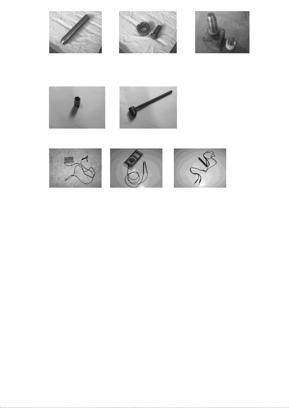
Use fault diagnosis tester...........................................................................................................................................36
Fault code table..................................................................................................................................................36
Fuel system................................................................................................................................................................38
Precautions.................................................................................................................................................................38
Disassembly schematic diagram................................................................................................................................39
Release the fuel pressure in the fuel line ...................................................................................................................44
Removal and inspection of fuel joint.........................................................................................................................44
Removal and inspection of fuel pump.......................................................................................................................45
Filter inspection.........................................................................................................................................................45
Disassembly and inspection of electric fuel pump ....................................................................................................46
Inspection of fuel pipe and fuel filter.........................................................................................................................47
Check the fuel common rail.......................................................................................................................................47
Engine........................................................................................................................................................................47
Precautions.................................................................................................................................................................47
Disassembly schematic diagram................................................................................................................................48
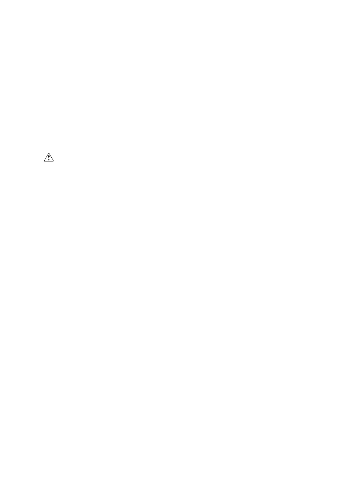
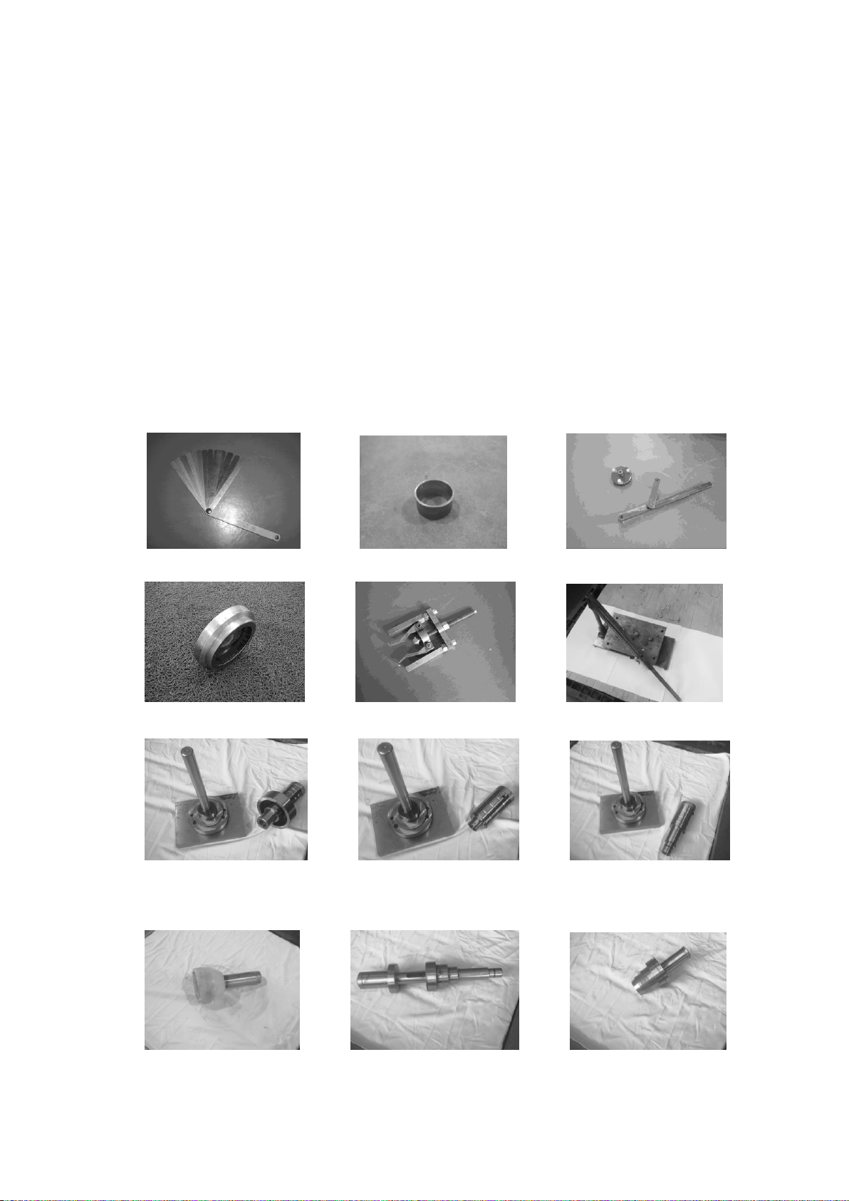
Special tool................................................................................................................................................................60
Check the compression pressure................................................................................................................................60
Check oil pressure......................................................................................................................................................60
Remove the engine ....................................................................................................................................................61
Pulley and timing belt................................................................................................................................................61
Disassembly and inspection.......................................................................................................................................62
Cylinder cover ...................................................................................................................................................62
Crankcase...........................................................................................................................................................66
Reinstallation.............................................................................................................................................................70
Assemble piston connecting rod........................................................................................................................70
Installing the piston rings...................................................................................................................................70
Installing piston .................................................................................................................................................70
Installing crankshaft...........................................................................................................................................70
Assemble the engine..........................................................................................................................................71
About water ...............................................................................................................................................................72
Top cover...................................................................................................................................................................72
Disassembly schematic diagram........................................................................................................................72
Disassembly and inspection...............................................................................................................................74
Bottom cover .............................................................................................................................................................74
Disassembly schematic diagram........................................................................................................................74
Disassembly and inspection...............................................................................................................................82
Steering handle..........................................................................................................................................................83
Disassembly schematic diagram........................................................................................................................83

Disassembly and inspection...............................................................................................................................84
Water unit and bracket...............................................................................................................................................85
Disassembly schematic diagram................................................................................................................................86
Disassembly and inspection of bracket......................................................................................................................95
Disassembly and inspection of water unit .................................................................................................................95
Hydraulic warping device..........................................................................................................................................96
Disassembly schematic diagram........................................................................................................................96
Disassemble.......................................................................................................................................................97
Manual warping device..............................................................................................................................................98
Disassembly schematic diagram........................................................................................................................98
Disassemble.......................................................................................................................................................99
Check the oil level.............................................................................................................................................99
Exhaust the air in the oil line of the hydraulic warping device..........................................................................99
Underwater part.......................................................................................................................................................101
Disassembly schematic diagram..............................................................................................................................101
Disassembly and inspection.....................................................................................................................................106
Propeller shaft and clutch block.......................................................................................................................106
Install the claw clutch......................................................................................................................................107
Housing cover of underwater unit ...................................................................................................................107
Install the oil seal and bearing of the housing cover........................................................................................107
Drive shaft .......................................................................................................................................................108
Shift cam..........................................................................................................................................................108
Gear .................................................................................................................................................................108
Forward gear bearing.......................................................................................................................................108
Check the housing of the underwater unit .......................................................................................................108
Check the water pipe .......................................................................................................................................108
Assemble the housing of the underwater unit..................................................................................................108
Install the underwater unit ...............................................................................................................................109
Selection of shim.....................................................................................................................................................109
Deviation value mark.......................................................................................................................................110
Pinion shim...................................................................................................................................................... 111
Forward gear shim........................................................................................................................................... 111
Reverse gear shim............................................................................................................................................111
Common faults and solutions ..................................................................................................................................112

1
Overview
Identification Mark
The serial number is printed on a label which is fixed to the port side of the clamp bracket
or the upper part of the rotary bracket. The serial number is recorded in the blank of the label to help
you order spare parts from dealers or for your reference in case the engine is stolen.
1. Position of the serial number
The SN indicates the following:
排量
发动机顺序号
年代号
Selection of propeller
The performance of the outboard motor is seriously affected by the propeller. Improper
selection will have adverse effects on the motor. When the ship runs in full load, the motor will
operate at low speed for a long time. At this time, the propeller with smaller pitch should be selected,
whereas the propeller with larger pitch should be selected to maintain the normal operation of the
engine. When the engine is at maximum load, if the throttle is half or more of the full throttle range,
the selected propeller is appropriate.
Propeller dimensions
Material
3-11
"
8
3
×12"
Aluminum alloy
3-11
"
8
1
×13"
Aluminum alloy
Protection at work
In order to prevent danger or accident during maintenance and improve work quality, please
observe the following safety regulations.
1. Fire prevention
Gasoline and various lubricating oils and greases are easy to burn; Keep away from heat
sources, sparks and open flames during operation.
2. Ventilation
Gasoline vapor and engine exhaust gas are highly toxic. Massive inhalation of such
substances can cause shock and even death. When testing the engine indoors, please keep
good ventilation conditions.
3. Self-protection
Wear protective glasses when drilling, grinding or using air compressors. Wear protective
gloves and safety shoes when necessary.
1
Outboard motor series number
Made Year Code
Engine displacement

2
4. Use of lubricants and sealants
Only products provided or recommended by Parsun can be used when maintaining and
repairing the outboard motor.
Under normal circumstances, the lubricant mentioned in this Manual will not damage
your skin. However, please take protective measures before use to reduce risks.
①Apply protective cream on both hands before overhauling the outboard motor;
②Replace and clean the clothes as soon as possible after they are contaminated by the
lubricant;
③Avoid skin contact;
④Wash your hands and skin carefully with soap and hot water after contact with the
lubricant;
⑤Wipe the spilled grease with a clean, lint-free rag.
5. Develop good work habits
①Tighten nuts, bolts and screws according to the specified torque from large size to
small size, from the center to the outside.
②Use recommended special tools to avoid damage to parts. Use the right tools in the
proper way.
Disassembly and assembly
When disassembling and assembling the outboard motor, please follow the following
principles:
1. Please use special tools when disassembling and assembling the parts of the outboard
motor;
2. Remove dust and dirt before decomposing the parts;
3. Apply engine oil on the contact surface of moving parts before assembly;
4. When installing the bearing, place the manufacturer's mark in the specified direction
and fully lubricate it;
5. Before installation, coat a thin layer of waterproof lubricating oil on the protruding part
and periphery of the oil seal;
6. After assembly, check whether the moving parts work normally.
Disposable parts
Parts such as gasket, oil seal, O-ring, cotter pin and spring ring are disposable parts, and they
must be replaced before reinstalling the outboard motor.
Pre-delivery inspection
To ensure the normal use by customers, please carry out the following inspection before delivery.
1. Check the fuel system.
Check whether the fuel hose is securely connected and whether the fuel tank is full.
Note:
As it is a four-stroke engine, premixed fuel cannot be used.
2. Check the oil level.
①Check engine oil level.
Pull out the oil dipstick and observe the oil level through the dipstick.

3
1. Oil dipstick 2. High mark 3. Low mark
Make sure the oil level is between the high mark and the low mark; Drain oil when the
oil level is above the high mark and add oil when the oil level is below the low mark.
②Check gear oil level
Unscrew the oil level plug and observe whether the gear oil overflows in the oil level
plug. If yes, install the oil level plug and tighten it according to the specified torque; If not,
fill with gear oil.
1. Oil level plug
3. Check the steering system.
Check whether the steering is smooth;
4. Check shift and throttle operation.
Check whether the shift operation is smooth; Check whether the throttle grip operates
smoothly from the full-close position to the full-open position.
5. Check the emergency stop switch assembly.
Check whether the engine stops when the emergency stop switch assembly is pressed
and hold or the engine stop safety line is pulled out.
6. Check the cooling water peep door.
Check the cooling water while the motor is running
Check whether the cooling water flows out of the
cooling water observation hole.
1. Cooling water observation hole
7. Running-in operation.
①1st hour: The engine runs at 2000 rpm or about half of the throttle.
②2nd hour: Run the engine at 3000 rpm or about 3/4 of the throttle.
③The next 8 hours: Avoid running at full throttle for 5 minutes continuously.
8. Inspection after running-in operation
①Check the gear oil for water.
②Check the fuel line for leaks.
1
1
1
1
2
1
3

4
③After running-in operation, run the engine at idle speed and use the washing tool to
flush the cooling water channel with fresh water.
9. After running-in operation, check the idle speed of the engine.
①Preheat the engine for 5 minutes.
②Measure the idle speed using tachometer.
If the specified value is not met, adjust it. Idle speed value: 900~1000rpm.
③After idle adjustment, accelerate the speed several times to check the engine stability.
Note:
Idle adjustment needs to be done by qualified maintenance personnel with
professional equipment; Adjusting at will may cause startup difficulty, weakness, jitter and
other faults of the engine.
Special tools and testing equipment
Various special tools and testing equipment will be used when repairing and maintaining
the outboard motor. Using these tools and equipment expertly and correctly can improve your work
efficiency and effectively avoid injuries to personnel and the outboard motor.
Special tools:
Clearance gauge Piston slideway Flywheel gripper and flywheel puller
Oil filter spanner Bearing puller Valve spring compressor kit
Underwater unit housing cover
bearing installation tool
Underwater unit housing cover
oil seal installation tool
Underwater unit housing cover
needle bearing installation tool
Underwater unit housing cover
assembly installation tool
Underwater unit needle bearing
installation tool
Drive shaft bearing jacket
installation tool

5
Drive shaft bearing
installation tool
Drive shaft seal oil seal
installation kit
Forward gear bearing
casing installation kit
Drive shaft spline sleeve Pinion nut spanner
Testing equipment:
Digital tachometer Digital multimeter Peak voltage adapter
Disassembly schematic diagram and symbol description
Description of disassembly schematic diagram

6
10
9
12
5
4
11
19
1817
放油螺塞垫片
机油尺组件
PLATE ,ANODE
阳极锁止片
F15-07010012
WASHER
平垫圈6
GB/T97.1-1985
BOLT
六角螺栓M6x20
GB/T5783-2000
六角螺栓M5x12
平垫圈5
BOLT
GB/T5783-2000
WASHER
GB/T97.1-1985
SEAL.ANODE
COVER ,ANODE
阳极盖板
F15-07010011
F15-07010009 阳极密封圈
ANODE
阳极
F25-02010005
22
21
20
19
18
17
16
15
1
1
1
1
1
1
1
1
REMARKSDESCRIPTIONPART NO. DESCRIPTION
零件名称(中文) 零件名称(英文)
1
6
2
3
4
5
7
8
9
10
11
12
13
14
1
1
1
1
1
1
WASHER ,PLAIN 15
13
HEXAGON BOLT
HEXAGON BOLT
2
2
2
1
1
1
F25-00000100
F25-02010100
F25-02010006
GB/T97.1-2000
GB/T5783-2000
F25-02010200
GB/T5783-2000
F25-00000014
F25-02000006
F25-02010007
F15-00000006
F15-04000003
F15-04000002
六角螺栓M6x25
粗滤器组件
六角螺栓M6X16
定位销8x12
油底壳
排气歧管座垫
定位销6x12
放油螺塞
放油口胶套
平垫圈6
溢流阀垫片
溢流阀组件 RELIEF VALVE AUY
HEXAGON BOLT
STRAINER,OIL
F25-02000007
GASKET
PLUG,OIL LEVEL
PIN,DOWEL
OIL SUMP
PIN,DOWEL
BOLT,OIL DRAIN
JACKET,OIL DRAIN
22 21
20
①
④
13
M14x12 mm
27 Nm
14
G②
③
①Exploded view of parts.
②Thread specification and specified torque.
③Points where oil, sealant or locking agent are applied
Parts list.
Symbol description
O
G
L
1277
L
1243
GM
Apply engine
oil
Apply waterproof
grease
Apply thread
locker 1277
Apply thread
locker 1243
Apply sealant

7
Specification
Outboard motor parameters
Item
Data
Item
Data
O
v
e
r
a
ll
d
i
m
e
n
si
o
n
s
Overall length
(B/F)
1173/768 mm
E
n
gi
n
e
Spark plug
DPR7EA-9 (NGK)
Overall width (B/F)
426/410 mm
Firing order
1-2-3
Overall
height
L
1361 mm
Maximum
generator output
12 V, 17A
S
1234 mm
Cooling
system
Water cooling
Stem board
height
L
508 mm
Exhaust
system
Through the propeller
hub
S
381 mm
F
u
el
a
n
d
oi
l
Lubrication
system
Wet lubrication
W
e
i
g
h
t
BWL-D
101.5 kg
Fuel type
Regular unleaded petrol
BWS-D
99.9 kg
Fuel grade
RON 91
FWL-T
100.6 kg
Type of engine
oil
Four-stroke engine oil
FWS-T
99 kg
Engine
oil
grade
API
SE, SF, SG, SH, SJ
P
e
rf
o
r
m
a
n
c
e
Maximum
output
F30
22 Kw@5500r/min
SAE
10W30, 10W40
F40
29.4 Kw@5500r/min
Engine oil
level
1.9 L(Change oil filter)
Full throttle
operating range
5000~6000 r/min
1.7 L (without changing
oil filter)
Maximum
fuel
consumpti
on
F30
10.5 L/h@6000 r/min
Type of gear
oil
Hypoid gear oil
F40
13.8 L/h@6000 r/min
Gear
oil
grade
API
GL-4
Idle (neutral
position)
950±50 r/min
SAE
90
Engine type
In-line four-stroke,
overhead cam
Gear oil level
0.43 L
Number of
cylinders
3
B
ra
c
k
et
Inclined angle
64°
E
n
g
i
n
e
Displacement
747 cm³
Steering angle
45°+45°
Cylinder bore ×
stroke
65 mm×75 mm
Trim angle
-3°~16°(when the stem
board is 12°)
Compression ratio
9.4
D
ri
vi
n
g
d
e
vi
c
e
Gear
F-N-R
Oil supply mode
Electronic fuel
injection
Transmission
ratio
2.0 (26/13)
Control
mode
B
Steering handle
Gear type
Spiral bevel gear
F
Remote control
Clutch type
Claw clutch
Start-up mode
Electric start
Propeller shaft
type
Spline
Ignition system
ECU
Propeller
direction
Clockwise (rear view)

8
Maintenance information
Engine
Item
Data
Item
Data
Pow
er
unit
Minimum
compression
pressure
840 kPa
Cyli
nder
bloc
k
Taper limit
0.08mm
Lubricating oil
pressure (idle
speed)
230 kPa
Roundness limit
0.05mm
Cyli
nder
cove
r
Buckling limit
0.1mm
Pisto
n
Diameter of piston
64.930~64.945mm
Inner diameter
of camshaft hole
37.00~37.025mm
Height of measuring
point
3mm (from bottom of
piston)
Piston to cylinder
clearance
0.055~0.085mm
Cyli
nder
bloc
k
Cylinder bore
65.00~65.013mm
Piston pin bore aperture
16.002~15.985mm
Wear limit
65.1mm
Outside diameter of piston
pin
15.965~16.008mm
Continued:
Item
Data
Item
Data
Pi
sto
n
rin
g
Top
ring
Thickness
1.17~1.19mm
Valv
e
Stem
diameter
Intake
valve
5.475~5.490mm
End face
width
2.25~2.4mm
Exhaust
valve
5.460~5.475mm
End gap
0.15~0.30mm
Inner diameter of valve
guide
5.500~5.518mm
Lateral
clearance
0.02~0.06mm
Clearance between
guide and valve stem
0.025~0.058mm
Second
ring
Thickness
1.47~1.49mm
Valve stem roundness
limit
0.03mm
End face
width
2.60~2.80mm
Valve
sprin
g
Free length
40.0mm
End gap
0.30~0.50mm
Minimum free length
38.4mm
Lateral
clearance
0.02~0.06mm
Tilt limit
1.7mm
Oil ring
Thickness
2.36~2.48mm
Co
nne
ctin
g
rod
Inner diameter of small
end
15.985~15.998m
m
End face
width
2.75mm
Inner diameter of large
end
36.000~36.016m
m
End gap
0.20~0.70mm
Oil clearance of large
end
0.020~0.052mm
Lateral
clearance
0.04~0.18mm
Thickness
of big-end
bearing
A Black
1.496~1.490 mm
Ca
ms
haf
t
Height
Intake
cam
30.83~31.09mm
B Brown
1.490~1.484mm
Exhaust
cam
30.83~31.09mm
Cra
nks
haft
Diameter of crankshaft
main journal
42.984~43.000 mm
Diameter of base
circle
25.90~26.10mm
Crank pin diameter
32.984~33.000 mm
Journal diameter
36.935~36.955mm
Crank pin width
21.00~21.07mm
Roundness limit
0.03mm
Large end backlash of
crankshaft
0.05~0.22mm

9
Journal oil
clearance
0.045~0.085mm
Roundness limit
0.05mm
Va
lv
e
Valve
clearance
(cold
position)
Intake
valve
0.15~0.25mm
Th
er
mo
stat
Open temperature
58~62ºC
Exhaust
valve
0.25~0.35mm
Full open temperature
70ºC
Valve
cone
Width
Intake
valve
1.84~2.97mm
Minimum opening height
of valve
3mm
Exhaust
valve
1.98~3.11mm
Cra
nkc
ase
Inner diameter of
crankshaft main journal
46.000~46.016mm
Contact width with
seat ring
0.9~1.1mm
Crankshaft main journal
oil clearance
0.012~0.044mm
Edge
thickne
ss
Intake
valve
0.8mm
Thickness
of
crankshaft
spindle
bearing
bush
A Black
1.500~1.494 mm
Exhaust
valve
0.9mm
B Brown
1.494~1.488mm
Head
diamete
r
Intake
valve
31.9~32.1mm
Exhaust
valve
25.9~26.1mm
Measurement conditions:
The ambient temperature is 20 ℃.
Underwater unit
Item
Data
Item
Data
Backlash
Pinion to forward gear
0.18~0.66mm
Optional gear
shim
0.10, 0.12, 0.15, 0.18, 0.30,
0.40, 0.50mm
Pinion to reverse gear
0.75~1.23mm
Electrical system
Ignition and ignition control system
Item
Data
Item
Data
Ignitio
n
timing
At idle speed
TDC 2º±0.5°
Peak output
voltage of
ignition coil
Secondary output
voltage
≥34KV
5000 r/min
BTDC 25°±0.5º
Primary resistance
1.2±0.12Ω
Spark plug clearance
0.8~0.9mm
Secondary resistance
12±1.2KΩ
Peak
output
voltage
of
magnet
o
1500 r/min
(no-load)
47.2 V
Output
peak
voltage
converter
of rectifier
regulator
1500 r/min (no-load)
41.9 V
3500 r/min (no-load)
106 V
3500 r/min
(no-load)
99.8 V
Magneto resistance
(green-green)
0.59±0.1Ω
* Data for reference only

10
Measurement conditions:
Unless otherwise specified, the ambient temperature is 20℃ during measurement.
Charging system
Item
Data
Item
Data
Ligh
ting
Coil
Outp
ut
peak
volta
ge
Start (no-load)
14.0 V
Fuse
30 A
1500 r/min (no-load)
45.0 V
Output
peak
voltage of
rectifier
regulator
1500 r/min (no-load)
13.0 V
3500 r/min (no-load)
102.0 V
3500 r/min (no-load)
13.0 V
Resistance
0.561~0.759 Ω
Seating torque
Specified torque
Mounting position
Name
Thread
specificati
on
Torque
Engi
ne
Spark plug
-
-
18 Nm
Flywheel
Nut
M20
157 Nm
Cylinder cover
Frist tightening
Bolt
M9
23 Nm
Second tightening
47 Nm
Frist tightening
Bolt
M6
6 Nm
Second tightening
12 Nm
Oil filter
-
-
18 Nm
Oil filter stud
-
-
40 Nm
Lock nut (rocker arm)
Nut
M6x0.75
13.5Nm
Engine assembly
Bolt
M8
21 Nm
Exhaust
cover plate
Frist tightening
Bolt
M6
6 Nm
Second tightening
12 Nm
Thermostat cover
Bolt
M6
7Nm
Crankcase
Frist tightening
Bolt
M8
15 Nm
Second tightening
30 Nm
Frist tightening
Bolt
M6
6 Nm
Second tightening
12 Nm
Continued:
Mounting position
Name
Thread
specification
Torque
Engine
Connecting
rod
Frist tightening
Bolt
M6
6 Nm
Second
tightening
17 Nm
Driven pulley
Bolt
M10
38 Nm
Underwater
unit
Underwater unit assembly
Bolt
M10
40 Nm
Bolt
M8
40 Nm
Water intake
Screw
M5
1 Nm
Oil drain bolt
Bolt
-
9 Nm
Oil inspection hole
Bolt
-
9 Nm

11
Pinion
Nut
M22
74 Nm
Propeller nut
Nut
M14
35 Nm
Above
water
Steering handle
Nut
M10
10 Nm
Steering handle
Self-locking
nut
M10
22 Nm
Exhaust manifold
Bolt
M6
10 Nm
Throttle grip
Screw
M5
2 Nm
Shift linkage bracket
Bolt
M6
10 Nm
Gear spring plate
Bolt
M6
10 Nm
Small cover plate of bottom
cover
Bolt
M6
10 Nm
Clamp bracket
Self-locking
nut
-
45 Nm
Oil drain bolt
Bolt
M14
27 Nm
Average torque
Dimensions
Overall dimensions
BWL-D:
Nut a
Bolt b
Torque
8mm
M5
5Nm
10mm
M6
8 Nm
12mm
M8
18 Nm
14mm
M10
36 Nm
17mm
M12
43 Nm
b
a

12

13
BWS-D:

14
FWL-T:

15
FWS-T:
This manual suits for next models
1
Table of contents
Other Parsun Outboard Motor manuals

Parsun
Parsun F2.6HP Guide

Parsun
Parsun F4BM User manual

Parsun
Parsun F5BM User manual

Parsun
Parsun T2CBMS User manual

Parsun
Parsun T9.8BM User manual

Parsun
Parsun F9.8FW User manual

Parsun
Parsun F15BM User manual

Parsun
Parsun F15AEFI BM User manual

Parsun
Parsun F6ABM User manual

Parsun
Parsun T40J BM User manual

Parsun
Parsun TE18BM User manual

Parsun
Parsun T50 BM User manual

Parsun
Parsun F30 BM User manual

Parsun
Parsun T90BM User manual

Parsun
Parsun F115 BEX-T User manual

Parsun
Parsun T15BM User manual

Parsun
Parsun T40BM User manual

Parsun
Parsun F25/20BM User manual

Parsun
Parsun F15BM User manual

Parsun
Parsun F9.8BM User manual