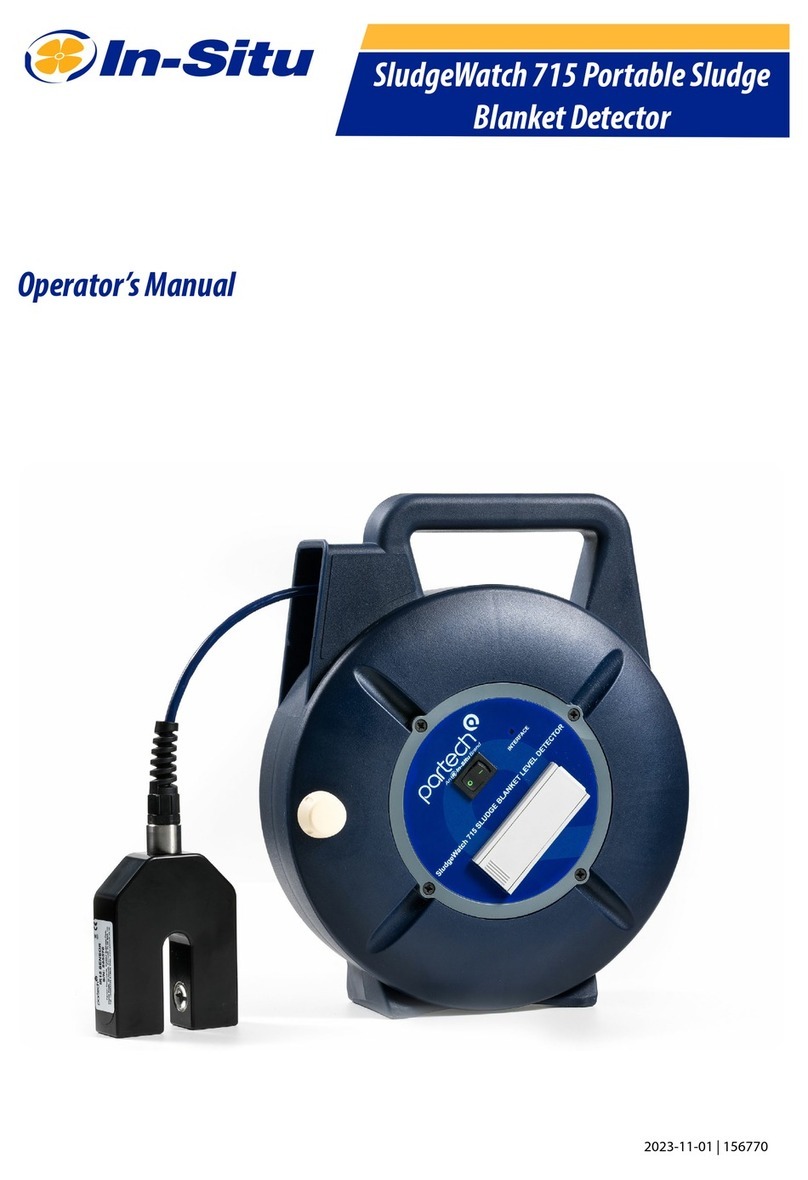
ParTech 715 User manual

INSTRUCTION MANUAL
715 Portable
Portable Sludge Blanket Detector

This page is left blank

715 Portable – Instruction Manual
Table of Contents
1 Introduction.................................................................................................................................4
2 Operation....................................................................................................................................5
2.1 Operation Test................................................................................................................5
2.2 Sludge Interface Detection..............................................................................................5
2.3 Cleaning..........................................................................................................................5
2.4 Reeling Technique..........................................................................................................5
3 Technical Support.......................................................................................................................6
3.1 Returning Equipment for Repair.....................................................................................6
4 Technical Specification...............................................................................................................7
4.1 General...........................................................................................................................7
4.2 Sensor.............................................................................................................................7
156770IM-Issue 07 Issue Date 24/10/2010 Page 3 of 10

715 Portable – Instruction Manual
1 Introduction
The 715 Portable Sludge Blanket Level Detector is designed for spot checking sludge interface
levels in settling tanks. The 715 works by measuring the change in the level of suspended solids
as the sensor is lowered into the tank. When the sensor reaches the sludge blanket, an audible
signal changes from a fast bleeping to a slow bleeping. A red LED provides a visual indication
that the sludge blanket has been detected. To enable measurement of the sludge interface
position in a tank, the sensor cable is marked in one-metre intervals from the sensor.
The 715 consists of two main parts, a cable reel and an IR sensor. The cable reel houses the
detector electronics and battery and is also used to store the sensor cable when not in use. The
715 is supplied with either an IR8, IR15, IR40 or IR100 sensor as required for the application.
The IR sensors use light attenuation across a single measurement gap to determine the
suspended solids in a solution. The length of the sensing gap determines the measurement
range of the sensor.
Page 4 of 10 156770IM-Issue 07 Issue Date 24/10/2010
Front Panel
Fixing Screws
(4off)
Battery
Compartment
Inteface LED
On / Off Switch
Sensor
Sensor
Cable Clip
Reeling
Handle

715 Portable – Instruction Manual
2 Operation
The 715 is ready for operation once the power switch is moved to the ON position. Before using
the 715 to determine the sludge interface position, it is worthwhile performing the operation test
below.
2.1 Operation Test
The operation of the 715 can be quickly checked. When the unit is switched on and the sensor
gap is clear (sensor in air or in clean water) the unit should emit a fast bleep and the LED should
not be illuminated. If the sensor gap is then blocked, the unit will switch to a slow bleep and the
LED will illuminate. Unblocking the sensor should return the unit to a fast bleep with the LED off.
2.2 Sludge Interface Detection
Release the sensor and allow it to hang below the cable reel. Slowly lower the sensor into the
settling tank, listening for a change in the sounder output. When the sound changes, the sludge
blanket has been detected, and the lowest visible cable marking indicates the position of the
sludge blanket below the supernatant surface.
2.3 Cleaning
After use the sensor should be cleaned by rinsing with clean water. On a regular basis the
sensor and sensor cable should be cleaned by rinsing with a solution of water and a mild
detergent. The cable reel can be cleaned using a damp cloth and mild detergent.
Note: The cable reel should not be immersed
2.4 Reeling Technique
When using the 715, the sensor cable should not be allowed to go slack when reeling the
sensor in or out. If the cable is allowed to become slack, it is possible for the cable to jam inside
the cable reel – if this does occur the cable must be carefully freed – the cable reel must not be
forced.
156770IM-Issue 07 Issue Date 24/10/2010 Page 5 of 10

715 Portable – Instruction Manual
3 Technical Support
Technical Support is available by phone, fax, or email, the details of which are shown below.
•Phone: +44 (0) 1726 879800
•Fax: +44 (0) 1726 879801
•Email: [email protected]
•Website: www.partech.co.uk
To enable us to provide quick and accurate technical support please have the following
information ready when you contact us:
•Serial Number or original purchase details
•Sensor Type, and Serial Number
•Application details
•Description of fault
3.1 Returning quipment for Repair
If equipment needs to be returned to Partech for repair or service the following address should
be used:
SERVICE DEPARTMENT
PARTECH INSTRUMENTS
ROCKHILL BUSINESS PARK
HIGHER BUGLE
ST AUSTELL
CORNWALL
PL26 8RA
UNITED KINGDOM
Please include the following information with the returned equipment. Also ensure that sensors
are adequately protected for transportation (Advice on packing can be provided by our service
department).
•Contact name and phone number
•Return address for equipment
•Description of fault or service required
•Any special safety precautions because of nature of application
Page 6 of 10 156770IM-Issue 07 Issue Date 24/10/2010

4 Technical Specification
4.1 General
Batter T pe: ..................................9VDC (Alkaline Batter PP3)
Batter Life......................................>200 Hours
Operating Temperature Range.......0 to 50
°
C
Storage Temperature Range..........-20 to +60
°
C
Environmental Rating......................IP65
Cable T pe......................................4 core, pol urethane coated
Standard Cable Length...................10 metres
Maximum Cable Length..................15 metres
Cable Marking.................................Ever Metre
Weight.............................................1.2 Kg
Dimensions.....................................280 x 230 x130mm (hxwxd)
4.2 Sensor
Measuring Principle.........................Light absorption
Light Source....................................Infrared LED, 950nm
Environmental Rating......................IP68
Materials..........................................Hastello , PVC, Epox Potting Compound
Parameter IR100 IR40 IR15 IR8
Maximum Supernatant (mg/l) 180 1350 9000 27000
Minimum Sludge (mg/l) 20 150 1000 3000
Weight (g) 350 300 250 250
Width (mm) 160 100 75 75
Height (mm) 95 95 95 95
Depth (mm) 25 25 25 25
The maximum supernatant value is the point at which the 715 will not detect sludge.
The minimum sludge value is the starting point for detection of sludge.
Note: The values quoted are based on the typical solids found on a municipal sewage
treatment works.
156770IM-Issue 07 Issue Date 24/10/2010 Page 7 of 10

This page is left blank

This page is left blank

Partech Instruments
Rockhill Business Park, Higher Bugle, St Austell, Cornwall, PL26 8RA, UK
Tel: +44(0)1726 879800
Email: [email protected] Web: www.partech.co.uk
Other manuals for 715
1
Table of contents
Other ParTech Security Sensor manuals