Partner CD-7220 User manual

CD7220/CD3220
VACUUM FLUORESCENT
CUSTOMER DISPLAY
MANUAL

CD7220/CD3220 CUSTOMER DISPLAY
2
INDEX
INTRODUCTION............................................................................................................................................................................................3
1. FEATURES ....................................................................................................................................................................................................4
2. ORDER INFORMATION.........................................................................................................................................................................5
3. GENERAL SPECIFICATIONS ..............................................................................................................................................................6
4. INTERFACE SPECIFICATIONS ..........................................................................................................................................................8
5. SYSTEM COMMAND DETAILS ........................................................................................................................................................11
6. COMMAND.................................................................................................................................................................................................13
7. CHARACTER SET...................................................................................................................................................................................22
8. DIMENSION...............................................................................................................................................................................................29
9. INSTALLATION GUIDE.......................................................................................................................................................................31

CD7220/CD3220 CUSTOMER DISPLAY
3
INTRODUCTION
Thank you for choosing the CD-7220/CD-3220 VFD Customer Pole Display. The CD-7220/CD-3220
provides both reliability and performance in a professional looking design. In this guide, you will find
connection and configuration information to help you connect the display to your computer. If you are a
programmer, you will find interface command details to allow you to exploit the advanced features of the
display.
The CD-7220/CD-3220 customer pole display uses a vacuum fluorescent display (VFD) tube presenting
bright and easy to read characters. Because of the VFD technology the display is viewable from a wide
angle. Users will appreciate not having to remain in a fixed viewing position to see the display, they
will be free to move forward in line and still keep the display readable. The CD-7220/CD-3220
customer pole display has 2 pole sections giving you the choice of 4 different display heights. The
display can be rotated up to 270° The head of the display can tilt by up to 35°. The combination of
these features gives you flexibility to tailor the display position to your unique application.
Data can be displayed on single side (CD-7220) or two sides (CD-7220D) of the display. You can
choose to show same or different message on the double-sided display. With 2 lines of 20 characters on
each side CD-7220 can display alphanumeric messages with 13 international characters. Additionally,
software utility is provided to transfer character dot pattern to ASCII code giving you the ability to
defined characters and demo message to download to the display EEPROM.
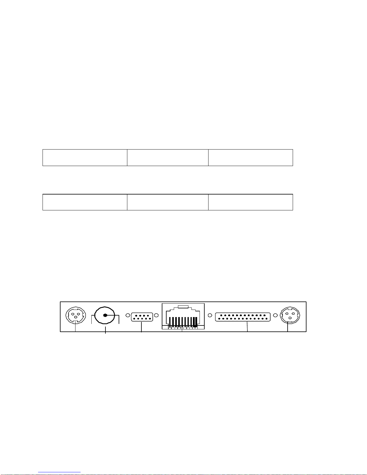
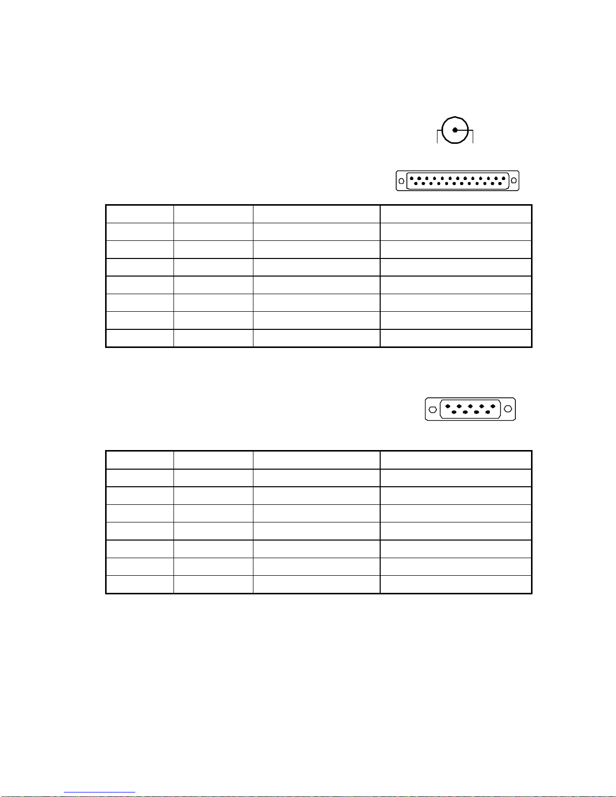
The CD7220/CD3220 customer pole display uses an easy to connect RS-232C serial port connection with
a wide range of available communication speeds from 300 to 38,400bps. CD7220’s pass through
function allows you to connect another serial device by sharing one single serial port on computer.
CD-7220/CD3220 also offers a variety of emulation modes including CD-5220II, Epson, ADM787,
ADM788, Aedes, Emax and Ultimate. The CD-7220’s universal design gives you the flexibility to
choose the application software best suited for your POS requirement.

CD7220/CD3220 CUSTOMER DISPLAY
4
1. FEATURES
•20 columns x 2 lines for each side (7220/3220 single sided, 7220D double sided.)
•Double-sided display (7220D) can have different data on each side.
•Display panel is adjustable both by tilting vertically and rotating horizontally.
•Configuration of baud rate, command emulation mode, and user defined font is selectable by
window based support software or by using external setting box.
•Command emulation modes include CD5220II, Epson, ADM787, ADM788, Aedex, Emax and
Ultimate.
•Support software has facility for designing user-defined characters and downloading setup
parameters to the display. Once in the display new characters are stored in non-volatile
EEPROM.
•Reverse characters (black characters on blue green background) can be specified using the
Epson command set.
•Display windowing commands are available using CD5220 or Epson command sets.
•Uses RS-232 serial interface with communication speeds from 300 to 38400 BPS.
•Display pass through function allows printer and display to share one port.

CD7220/CD3220 CUSTOMER DISPLAY
5
2. ORDER INFORMATION
CD-XXXX DST12 110 PT
Table 1-1
Model No.
CD-7220
CD-3220
Pass through function
PT: with pass through cable
Blank: without pass through cable
Face
D: Double sided
Blank: Single sided
Power Adapter
N: without power adapter
110: 110V AC power adapter
EU: 230V AC power adapter
with EU power cord
UK: 230V AC power adapter
with UK power cord
B: power bracket kit for connec
tion
with PC power supply
Base
T: PTC rectangular free
C: space-
saving round base
with metal plate
Power Input
05: 5V DC
12: 12V DC
24: 24V DC
Interface
S: Serial
U: USB

CD7220/CD3220 CUSTOMER DISPLAY
6
3. GENERAL SPECIFICATIONS
ITEM CD7220D CD7220
Display method Vacuum fluorescent display
Display color Blue green
Number of characters 80 characters ( 20 columns x 2 lines with
double side )
40 characters ( 20 columns x 2 lines)
Brightness 700 cd/m2
Character type 96 alphanumeric
13 kinds of international character set and 1 user-define character set
Character font 5 x 7 dot matrix, comma, decimal point
Character size 9.2mm x 5.25mm
Character pitch 8.3mm
Power supply 5VDC or 12VDC or 24VDC or 33VDC
Power consumption 8W 4.5W
MTBF(power on time) 25000 hours
Dimensions 230(W)x100(H)x42(D)mm
Viewing angle ±30 degrees
Rotation angle Maximum 270 degrees
Weight 0.9 Kg
Environmental Condition
Operating
Temperature 5 -45℃
Humidity Less then 95%
Storage
Temperature -5 -55℃
Humidity Less then 95%
Safety FCC class B
、
CE
Table 1-2

CD7220/CD3220 CUSTOMER DISPLAY
7
ITEM CD3220
Display method Vacuum fluorescent display
Display color Blue green
Number of characters 40 characters(20 columns × 2lines)
Brightness 700 cd/m2
Character type 96 alphanumeric
13 kinds of international character set and 1 user-define set
Character font 5 ×7dot matrix
Character size 3.5mm×5.0mm
Character pitch 2mm
Power supply 5VDC or 12VDC or 24VDC
Power consumption 5W
MTBF(power on time) 25000hours
Dimensions 170(W)×70(H)×45(D)mm
Viewing angle 士30 degrees
Rotation angle Maximum 270 degrees
Weight 0.9Kg
Temperature 5-45℃
Operating Humidity Less then 95%
Temperature -5-55℃
Environmental
Conditions Storage Humidity Less then 95%
Safety FCC class B
、
CE

CD7220/CD3220 CUSTOMER DISPLAY
8
4. INTERFACE SPECIFICATIONS
4.1 Serial port (RS232C)
4.1.1 Serial port (RS232C) communication
(a) This interface specification is based on EIA RS232C baud rate 300 to 38400 BPS,
8 data bits, none parity, 1 or more stop bits
(b) Serial port (RS232C) communication data link
Data link flow chart:
PC/HOST display display printer printer PC/HOST
Control for RTS and DTR :
PC/HOST display display printer printer PC/HOST
(c) CD7220 will activate DTR or RTS signal to PC/host in the following two conditions:
1. Printer will activate DTR or RTS signal.
2. The pass through buffer in CD7220/CD3220 is full ( 200 bytes ) .
* If PC/host keep transmitting the data to printer when CD7220/CD3220 activate DTR or RTS, the data will be lost.
4.1.2 Serial port interface for rectangle basic section
(a) Serial port interface connector position for rectangle basic section
GND 5V or 12V
24V
OUTPUT
Power input
DC JACK RS232C to
Printer (pass through)
Display panel connector (phone jack) RS232C to
PC/Host
24V
INPUT
(b) Power input
Connector type: DC JACK (5.5/2.1)
Hoshiden connector for 24VDC

CD7220/CD3220 CUSTOMER DISPLAY
9
(c) RS232C to PC/HOST connector: D-sub 25 pin female pin assignment
Pin No. Signal Direction Function description
1FG Frame ground
2TXD From printer to PC/Host Printer status data
3RXD Input Receive data
4RTS Output Display/printer ready signal
5CTS From PC/HOST to printer Host Ready signal
6DSR From PC/HOST to printer Host ready signal
7GND Signal ground
16 V+ Input If using power built-in
20 DTR Output Display/printer ready signal
Table 4-1
(d) RS232C to printer connector: D-sub 9 pin male pin assignment
Pin No. Signal Input / Output direction Function description
2RXD From printer to PC/Host Printer status data
3TXD Output Transmit data
4DTR From PC/HOST to printer Host ready signal
5GND Signal ground
6DSR Input Printer ready signal
7RTS From PC/HOST to printer Host ready signal
8CTS Input Printer ready signal
Table 4-2

CD7220/CD3220 CUSTOMER DISPLAY
10
4.1.3 Serial port interface to the space-saving base portion
(a) Power cable connector: DC jack (5.5/2.1)
(b) RS232C interface pass through cable connector: D-sub 25 pin female pin
assignment
Pin No. Signal Input / Output direction Function description
2RXD From printer to PC/Host Printer status data
3TXD Output Transmit data
4CTS Input Printer ready signal
5RTS From PC/HOST to printer Host ready signal
6DTR From PC/HOST to printer Host ready signal
7GND Signal ground
20 DSR Input Printer ready signal
Table 4-3
(c) RS232C interface to PC/HOST cable, PC/HOST side connector pin assignment
Connector type: D-sub 9 pin (Male)
Pin No. Signal Direction Function description
2TXD From printer to PC/Host Printer status data
3RXD Input Receive data
4DSR From PC/HOST to printer Host ready signal
5GND Signal ground
6DTR Output Display/printer ready signal
7RTS Output Display/printer ready signal
8CTS From PC/HOST to printer Host ready signal
Table 4-4
GND 5V or 12V
1 13
14 25
1
9 6
5

CD7220/CD3220 CUSTOMER DISPLAY
11
5. SYSTEM COMMAND DETAILS
5.1 Baud rate
STX 05 B n ETX /Set baud rate and keep it with EEPROM/
ASCII Format STX 05 B n ETX
Dec. Format [02][05][66] n [03]
Hex. Format [02h][05h] [42h] n [03h] 30h<n<37h
Description Change the display communication baud rate. The baud rate setting can be selected from 300 to 38400.
The setting function will be saved to EEPROM.
NBaud rate
30h 9600
31h 4800
32h 2400
33h 1200
34h 600
35h 300
36h 38400
37h 19200
5.2 International character set
STX 05 S n ETX Change international character set
ASCII Format STX 05 S n ETX
Dec. Format [02][05][83] n [03]
Hex. Format [02h][05h] [53h] n [03h] 30h<n<3fh
Description Change the display international character font. A total of 16 different character fonts to select from.
The setting function will be saved to EEPROM.
nInternational font nInternational font
30h U.S.A 38h JAPAN
31h FRANCE 39h NORWAY
32h GERMANY 3Ah DENMARK II
33h U.K 3Bh SLAVONIC
34h DENMARK I 3Ch RUSSIA
35h SWEDEN 3Dh Factory define
36h ITALY 3Eh Factory define
37h SPAIN 3Fh User define pattern
5.3 Command type select
STX 05 C n ETX Change command type
ASCII Format STX 05 C n ETX
Dec. Format [02][05][67] n [03]
Hex. Format [02h][05h] [43h] n [03h] 30h≦n ≧37h
Description This command will change the command type and initialize the display. The display emulation mode
is based on CD5220II/ESC POS/ADM787/ADM788/ UTC/AEDEX/EMAX mode. The setting function
will be saved to EEPROM.
nCommand type nCommand type
30h DSP800 34h AEDEX
31h ESC/POS 35h UTC/P
32h ADM788 36h UTC/S
33h ADM787 37h CD5220

CD7220/CD3220 CUSTOMER DISPLAY
12
5.4 Reset EEPROM
STX 05 07 n ETX Reset EEPROM
ASCII Format STX 05 07 n ETX
Dec. Format [02][05][07][n][03]
Hex. Format [02h][05h][07h][n][03h]
Description This command will reset the content of EEPROM (eg. demo scroll data, user-define character, baud
rate setting.)
n=31h clear all EEPROM contents
n=32h clear upper line data message
n=33h clear lower line data message
5.5 Save data for demo display
STX 05 L n m ETX Save demo message to EEPROM
ASCII Format STX 05 L n m ETX
Dec. Format [02][05][76] n m [03]
Hex. Format [02h][05h][4Ch] n m [03h]
Description Save demo message for upper line and bottom line
n = 31h save data message for upper line
n = 32h save data message for lower line
m = data message; the maximum data character is under 200
5.6 Run Demo message
STX 05 D 08 ETX Run demo message
ASCII Format STX 05 D 08 ETX
Dec. Format [02][05][68][08][03]
Hex. Format [02h][05h][44h][08][03h]
Description
Run demo message for the display
5.7 Set Communication Option
STX 05 P n ETX Set the communication parity
ASCII Format STX 05 P n ETX
Dec. Format [02][05][80] n [03]
Hex. Format [02h][05h][50h] n [03h] 31h<n<36h
Description
Change the display communication parity. Set 7 or 8 data bit and the parity set for even, odd, or
non-parity.
nParity
31h N-8-1
32h N-7-1
33h E-8-1
34h E-7-1
35h O-8-1
36h O-7-1

CD7220/CD3220 CUSTOMER DISPLAY
13
6. COMMAND
6.1 Command list
6.1.1 CD 5220-II STANDARD MODE
Command Code description (hex) Function description
ESC DC1 1B 11 overwrite mode
ESC DC2 1B 12 vertical scroll mode
ESC DC3 1B 13 horizontal scroll mode
ESC Q A ..........CR 1B 51 41 [n ]x20 0D set the string display mode, write string to upper line
ESC Q B ..........CR 1B 51 42 [n ]x20 0D set the string display mode, write string to lower line
ESC Q D ..........CR 1B 51 44 [n ]x20 0D upper line message scroll continuously
ESC [ D 1B 5B 44 move cursor left
BS 08 move cursor left
ESC [ C 1B 5B 43 move cursor right
HT 09 move cursor right
ESC [ A 1B 5B 41 move cursor up
ESC [ B 1B 5B 42 move cursor down
LF 0A move cursor down
ESC [ H 1B 5B 48 move cursor to home position
HOM 0B move cursor to home position
ESC [ L 1B 5B 4C move cursor to left-most position
CR 0D move cursor to left-most position
ESC [ R 1B 5B 52 move cursor to right-most position
ESC [ K 1B 5B 4Bmove cursor to bottom position
ESC l x y 1B 6C x y
1<x<20,y=1,2 move cursor to specified position
ESC @ 1B 40 initialize display
ESC W s x1 x2 y 1B 57 1 x1 x2 y 1<x1<x2<20
y=1,2 reset window range at horizontal scroll mode
CLR 0C clear display screen, and clear string mode
CAN 18 clear cursor line, and clear string mode
ESC * n 1B 2A n 1<=n<=4 brightness adjustment
ESC & s n m [a(p1..pa)]x
(m-n+!) 1B 26 1 n m [a(p1..pa)]x (m-n+1)
20h<n<=m<=FFh
a=1-5 , p1..p5 =row1..row5
define download characters.
ESC ? 1B 3F delete download characters.
ESC % 1B 25 select/cancel download character set.
ESC _ n 1B 5F n n=0,1 set cursor ON/OFF
ESC f n 1B 66 n select international fonts
ESC c n 1B 63 n select fonts, ASCII code or JIS code
ESC s 1 1B 73 01 store user-define character into EEPROM
ESC d 1 1B 64 01 restore user-define character from EEPROM
ESC = n 1B 3D n
n=1; enable printer, disable display
n=2; disable printer, enable display
n=3; enable printer, enable display
n=4; message for customer side
(for CD7220D only)
n=5; message for operator side
(for CD7220D only)
default n=2
select peripheral device, display or printer: display for
customer side or display for operator side
Table 6-1
(REMARK)
* While usingcommand "ESC QA" or "ESC QB", these two commands can be used with terminal printer: TP2688 or TP3688
* While using command "ESC QA" or "ESC QB", other commands can not be used except when using command "CLR" or "CAN" to change operating mode.
* When using command "ESC QD", the upper line message will scroll continuously until a new command is received, it will then clear the upper line and
move the cursor to the upper left-end position.

CD7220/CD3220 CUSTOMER DISPLAY
14
Set international font for CD7220/CD3220 (Table 6-2) Select code for CD7220/CD3220 (Table 6-3)
nInternational font set nInternational font set nInternational code set
A
G
I
J
U
F
S
U.S.A.
GERMANY
ITALY
JAPAN
U.K.
FRANCE
SPAIN
N
W
D
E
L
R
NORWAY
SWEDEN
DENMARK I
DENMARK II
SLAVONIC
RUSSIA
reserved
A
J
R
L
P
W
Compliance with ASCII code
Compliance with JIS code
Compliance with RUSSIA code
Compliance with SLAVONIC code
PC858
WPC1252
6.1.2 ADM787/788 command list
Command Code description (hex) Function description
CLR 0C clear display
CR 0D carriage return
SLE1 0E clear upper line and move cursor to upper left-end
position
SLE2 0F clear bottom line and move cursor to bottom left-end
position
DC0 10 n set period to upper line, last n position 31h<n<37h
DC1 11 n set line blinking, upper line n=‘1’, bottom line n=‘2’
DC2 12 n clear line blinking, upper line n=‘1’, bottom line n=‘2’
SF1 1E clear field 1 and move cursor to field 1, first position
SF2 1F clear field 2 and move cursor to field 2, first position
Table 6-4
6.1.3 UTC standard mode command list
Command Code description (hex) Function description
BS 08 back space
HT 09 horizontal tab
LF 0A line feed
CR 0D carriage return
DLE 0F display position
DC1 11 overwrite display mode
DC2 12 vertical scroll mode
DC3 13 cursor on
DC4 14 cursor off
ESC d 1B 64 change to UTC enhanced mode
US 1F clear display
Table 6-5
6.1.4 UTC enhanced mode command list
Command Code description (hex) Function description
ESC u A ....CR 1B 75 41 [ data x 40] 0D upper line display
ESC u B ....CR 1B 75 42 [ data x 40] 0D bottom line display
ESC u D ....CR 1B 75 44 [ data x 40] 0D upper line message scroll continuously
ESC u E ....CR 1B 75 45 hh‘:’mm 0D
h,m=‘0’-‘9’ display time
ESC u F ....CR 1B 75 46 [ data x 40] 0D upper line message scroll once
ESC u H ....CR 1B 75 48 n m 0D 20h<n,m change attention code
ESC u I ....CR 1B 75 49 [ data x 40] 0D two line display
ESC RS CR 1B 0F 0D change to UTC standard mode
Table 6-6

CD7220/CD3220 CUSTOMER DISPLAY
15
6.1.5 AEDEX mode command list
Command Code description (hex) Function description
! # 1 ....CR 21 23 31 [data x 40] upper line display
! # 2 ....CR 21 23 32 [data x 40] bottom line display
! # 4 ....CR 21 23 34 [data x 40] upper line message scroll continuously
! # 5 ....CR 21 23 35 hh‘:’mm 0D
h,m=‘0’-‘9’ display time
! # 6 ....CR 21 23 36 [data x 40] upper line message scroll once pass
! # 8 ....CR 21 23 38 n m 0D 20h<n,m change attention code
! # 9 ....CR 21 23 39 [data x 40] two line display
Table 6-7
6.1.6 DSP-800 mode command list
Command Code description (hex) Function descriptions
EOT SOH I n ETB 04 01 49 n 17 select international character set
EOT SOH P n ETB 04 01 50 n 17 n=31h-58h move cursor to specified position
EOT SOH C n m ETB 04 01 43 n m 17
31h<n<m<58h clear display range from n position to m
position and move cursor to n position
EOT SOH S n ETB 04 01 53 n 17 n=31h-35h save current view message to n layer for demo view
data
EOT SOH D n m ETB 04 01 44 n m 17
n=31h-4Fh m=31h-33h display the saved demo message
EOT SOH A n ETB 04 01 41 n 17 n=31h-34h brightness adjustment
EOT SOH F n ETB 04 01 46 n 17 00h<n<FFh blink display screen
EOT SOH & n [px5] ETB 04 01 26 n p1...p5 17, 20h<ndefine download characters
EOT SOH ? n ETB 04 01 3F n 17 20h<n delete download characters
EOT SOH = n ETB 04 01 3D n 17
select peripheral device
select printer n=‘1’, display n=‘2’
EOT SOH % ETB 04 01 25 17 initialize display
EOT SOH @ ETB 04 01 40 17 execute self-test
EOT SOH B n N ETB 04 01 42 n 4E 17 n=31h-36h set baud rate and parity
Table 6-8
(REMARK)
* International font set (Table 6-9)
nInternational font set
30h U.S.A.
31h France
32h Germany
33h U.K.
34h Denmark I
35h Sweden
36h Italy
37h Spain
38h Japan
39h Norway
3Ah Denmark II

CD7220/CD3220 CUSTOMER DISPLAY
16
6.1.7 EPSON ESC/POS command list
Command Code description(hex) Function description
HT 09 move cursor right
BS 08 move cursor left
US LF 1F 0A move cursor up
LF 0A move cursor down
US CR 1F 0D move cursor to right-end position
CR 0D move cursor to left-end position
HOM 0B move cursor to home position
US B 1F 42 move cursor to bottom position
US $ x y 1F 24 x y 1<x<20,y=1,2 move cursor to specified position
CLR 0C clear display screen
CAN 18 clear cursor line
US X n 1F 58 n 1<n<4brightness adjustment
US E n 1F 45 n 0<n<255 blink display screen
ESC @ 1B 40 initialize display
ESC t n 1B 74 n 1<n<15 select character code table
ESC R n 1B 52 n 1<n<15 select international character set
US r n 1F 72 n n=0,1 select/cancel reverse character
US MD1 1F 01 specify overwrite mode
US MD2 1F 02 specify vertical scroll mode
US MD3 1F 03 specify horizontal scroll mode
ESC & s n m
[a(p1..pa)]x m-n1B 26 1 n m [a(p1..pa)]x m-n
20h<n<m<FFh; a=1-5, p1..p5=row1..row5 define download characters
ESC ? 1B 3F delete download characters
ESC % 1B 25 select/cancel download character set
ESC W n s x1 y1
x2 y2 1B 57 n s x1 y1 x2 y2
n=1-4,s=0,1,1<x1<x2<20; 1<y1<y2<2reset window range
ESC = n 1B 3D n (default n=2)
n=1; enable printer, disable display
n=2; disable printer, enable display
n=3; enable printer, enable display
For CD7220D only:
n=4; message for customer side
n=5; message for operator side
select peripheral device
US : 1F 3A set starting/ending position to define macro
US ^ n m 1F 5E n m, 0<(n, m)<255 execute and quit macro
US @ 1F 40 execute self-test
ESC s 1 1F 73 01 store defined download character to EEPROM
ESC d 1 1F 64 01 restore user-define character from EEPROM
ESC T h m 1B 54 h m ,0<h<23 0<m<59 display time
US . n 1F 2E n , n = a displayable character code specify period
US , n 1F 2C n , n = a displayable character code specify comma
US ; n 1F 3B n , n = a displayable character code specify semicolon (period + comma)
US # n m 1F23 n m , n= 0 or 1 , 0<m<20 turn annunciator ON/OFF
Table 6-10
Set international font for ESC/POS (Table 6-11) Select code for ESC/POS (Table 6-12)
nInternational font set nInternational font set n
International font set (80
H-FFH)
0
1
2
3
4
5
6
U.S.A.
FRANCE
GERMANY
U.K.
DENMARK I
SWEDEN
ITALY
7
8
9
10
11
12
15
SPAIN
JAPAN
NORWAY
DENMARK II
SLAVONIC
RUSSIA
Reserved
0
1
2
3
4
5
6
7
19
16
Page 0,(PC437:U.S.A.,standard Europe)
Page 1,(Katakana for Japan )
Page 2,(PC850:mul
tilingual)
Page 3,(PC860:Portuguese)
Page 4,(PC863:Canadian
-French)
Page 5,(PC865:Nordic)
Page 6,(SLAVONIC)
Page 7,(RUSSLA)
Page 8,(PC858:Euro)
Page 9,(WPC1252)

CD7220/CD3220 CUSTOMER DISPLAY
17
6.2 CD7220/CD3220 standard command details
ESC DC1 /Overwrite mode/
ASCII Format ESC DC1
Dec. Format [027][017]
Hex. Format [1Bh][11h]
Description Change the display mode to the overwrite mode. In this mode, the cursor will move rightward and
begin from the upper left-end position. When the cursor reached the end of the upper line, the cursor
will move down to the bottom left-end position to continue. When the cursor reached the end of the
bottom line, it will move up to the upper left-end position and overwrite the previous characters.
ESC DC2 /Vertical scroll mode/
ASCII Format ESC DC2
Dec. Format [027][018]
Hex. Format [1Bh][12h]
Description Change the display mode to the vertical scroll mode. In this mode, the cursor will move rightward.
The cursor will begin from the upper left-end position until it reached the end of the upper line, the
cursor will then move down to the bottom left-end position to continue until it reached the end of the
bottom line. Then, CD7220/CD3220 will scroll the bottom line up to replace the upper line. The
bottom line will be cleared,and the cursor will continue to the first position of the bottom line.
ESC DC3 /Horizontal scroll mode/
ASCII Format ESC DC3
Dec. Format [027][019]
Hex. Format [1Bh][13h]
Description Change the display mode to the horizontal mode. In this mode, the extend of the cursor activity is
bond by predefined range, limited to the upper line. (Please refer to Set or cancel window command),
where the default window is the whole upper line. Once the cursor activity reached the end of the
range, the characters that comes there after will push displayed characters forward from behind.
ESC Q A d1d2d3d4d5d6.......dn CR
ESC Q B d1d2d3d4d5d6.......dn CR /Set the string display mode, and write string to display/
ASCII Format ESC Q A d1d2d3d4d5d6...dn CR
ESC Q B d1d2d3d4d5d6...dn CR
Dec. Format [027][081][065] d1d2d3..dn [013]
[027][081][066] d1d2d3..dn [013]
Hex. Format [1Bh][51h][41h] d1d2d3..dn [0Dh]
[1Bh][51H][42h] d1d2d3..dn [0Dh] {20h<dn<ffh}
Description Set the string display mode, write to upper or lower line d1 d2 d3 . . . dn {1<n<20}
“A”stands for the upper line, “B”stands for the lower line. The string display mode will be cancelled
and back to last mode after receive CLR or CAN.
ESC Q D d1d2d3d4d5d6.......dn CR /Upper line message scroll continuously
ASCII Format ESC Q D d1d2d3d4d5d6...dn CR
Dec. Format [027][081][068] d1d2d3..dn [013]
Hex. Format [1Bh][51h][44h] d1d2d3..dn [0Dh] {20h<dn<ffh}
Description The message (previously defined) will scroll continuously in the horizontal direction until a new
command is received.

CD7220/CD3220 CUSTOMER DISPLAY
18
ESC [ D /Move cursor left/
BS /Move cursor left/
ASCII Format ESC [ D
Dec. Format [027][091][068]
Hex. Format [1Bh][5Bh][44h]
ASCII Format BS
Dec. Format [008]
Hex. Format [08h]
Description When the current cursor is at the left-end position, this command operates differently depends on the
display mode.
1. Overwrite mode: When the cursor reached the left-end of the lower line, it will continue to the right-end
of the upper line, overwrite previous characters. When it reached the left end of the upper line, it will
continue to the right-end of the lower line.
2. Vertical scroll mode: When the cursor reached the left-end of the lower line, the lower line will scroll
up and replace the previous upper line, the lower line will be cleared and the cursor will continue to the
right end of the lower line.
3. Horizontal scroll mode: The cursor will remain stationary.
ESC [ C /Move cursor right/
HT /Move cursor right/
ASCII Format ESC [ C
Dec. Format [027][091][067]
Hex. Format [1Bh][5Bh][43h]
ASCII Format HT
Dec. Format [009]
Hex. Format [09h]
Description Move the cursor to the right. When the cursor reached the right-end, this command operates differently
depending on the display mode.
1. Overwrite mode: When the cursor reached the right-end of the lower line, it will continue to the left-end
of the upper line, overwrite previous characters. When it reached the right-end of the upper line, it
will continue to the right-end of the lower line.
2. Vertical scroll mode: When the cursor reached the right-end of the lower line, the lower line will scroll
up to replace the upper line, the lower line is cleared and ready to continue characters there after.
3. Horizontal scroll mode: The cursor will remain stationary.
ESC [ A /Move cursor up/
ASCII Forma t ESC [ A
Dec. Format [027][091][065]
Hex. Format [1Bh][5Bh][41h]
Description Move the cursor up one line. When the cursor is on the upper line, this command operates differently
depending on the display mode.
1. Overwrite mode: The cursor is moved to the same column on the lower line.
2. Vertical scroll mode: The characters display on the upper line are scrolled to the lower line, and the
upper line is cleared. The cursor will remain at the same position.
3. Horizontal scroll mode: The cursor will remain stationary.
ESC [ B /Move cursor down/
L F /Move cursor down/
ASCII Format ESC [ B
Dec. Format [027][091][066]
Hex. Format [1Bh][5Bh][42h]
ASCII Format LF
Dec. Format [010]
Hex. Format [0Ah]
Description Move the cursor down one line. When the cursor reached the lower line, this command operates
differently depending on the display mode.
1. Overwrite mode: The cursor is moved to the same column on the upper line.
2. Vertical scroll mode: The characters display on the lower line are scrolled to the upper line, and the
lower line is cleared. The cursor will remain at the same position.
3. Horizontal scroll mode: The cursor will remain stationary.

CD7220/CD3220 CUSTOMER DISPLAY
19
ESC [ H /Move cursor to home position/
HOM /Move cursor to home position/
ASCII Format ESC [ H
Dec. Format [027][091][072]
Hex. Format [1Bh][5Bh][48h]
ASCII Format HOM
Dec. Format [011]
Hex. Format [0Bh]
Description The cursor will move to the left-end position of the upper line
ESC [ L /Move cursor to left-most position/
CR /Move cursor to left-most position/
ASCII Format ESC [ L
Dec. Format [027][091][076]
Hex. Format [1Bh][5Bh][4Ch]
ASCII Format CR
Dec. Format [013]
Hex. Format [0Dh]
Description The cursor will be moved to the left-end position of the current line.
ESC [ R /Move cursor to right-most position/
ASCII Format ESC [ R
Dec. Format [027][091][082]
Hex. Format [1Bh][5Bh][52h]
Description The cursor will be moved to the right-end position of the current line.
ESC [ K /Move cursor to bottom position/
ASCII Format ESC [ K
Dec. Format [027][091][075]
Hex. Format [1Bh][5Bh][4Bh]
Description The cursor will be moved to the right-end position on the lower line.
ESC 1 x y /Move cursor to specified position/
ASCII Format ESC l x y
Dec. Format [027][108] x y { 1<x<20 , 1<y<2}
Hex. Format [1Bh][6Ch][x][y]
Description The cursor will be moved to the x column on the y line.
ESC @ /Initialize display/
ASCII Format ESC @
Dec. Format [027][064]
Hex. Format [1Bh][40h]
Description The data in the input buffer will be cleared and reset from default.
ESC W s x1x2 y /Reset the window/
ASCII Format ESC W s x1 x2 y
Dec. Format [027][087][000]
[027][087][001] x1 x2 y { 1<=x1<=x2<=20 , 1<=y<=2 }
Hex. Format [1Bh][57h][000]
[1Bh][57H][01h][x1][x2][y]
Description Reset the window on the display. When s = 0, window is cancelled (values: x1, x2, and y are not
required.)
When s = 1 the window will be reset (values: x1, x2, and y are required.) The x1 and x2 set the
position of the left column and right column, respectively, of the window. The y sets the upper line or
the lower line of the window. This function is valid within the horizontal mode.

CD7220/CD3220 CUSTOMER DISPLAY
20
CLR /Clear display screen, and clear string mode/
ASCII Format CLR
Dec. Format [012]
Hex. Format [0Ch]
Description All the display characters will be cleared, and the string mode will be cancelled.
CAN /Clear current line, and cancel string mode/
ASCII Format CAN
Dec. Format [024]
Hex. Format [18h]
Description The current line is cleared, and the string mode is cancelled.
ESC * n /Brightness adjustment /
ASCII Format ESC * n
Dec. Format [027][042] n {3<=n<=4}
Hex. Format [1Bh][2Ah][n]
Description Adjust the brightness of the vacuum fluorescent display.
When n = 3 ,brightness = 70 %
When n = 4 ,brightness=100 %
ESC _ n /Set cursor ON or OFF /
ASCII Format ESC _ n
Dec. Format [027][095] n {0<=n<=1}
Hex. Format [1Bh][5Fh][n]
Description: Set cursor ON or OFF
When n = 0, cursor is OFF
When n = 1, cursor is ON
ESC f n /Select international font/
ASCII Format ESC f n
Dec. Format [027][102] n
Hex. Format [1Bh][66h][n]
Description Set international font
nInternational font set nInternational font set
A
G
I
J
U
F
S
U.S.A.
GERMANY
ITALY
JAPAN
U.K.
FRANCE
SPAIN
N
W
D
E
L
R
NORWAY
SWEDEN
DENMARK I
DENMARK II
SLAVONIC
RUSSIA
reserved
Table 6-11
ESC c n /Select fonts /
ASCII Format ESC c n
Dec. Format [027][099] n
Hex. Format [1Bh][63h][n]
Description Select fonts
nInternational font set nInternational
A
Jcompliance with ASCII code
compliance with JIS code R
Lcompliance with RUSSIA code
compliance with SLAVONIC code
Table 6-12
Other manuals for CD-7220
1
This manual suits for next models
1
Table of contents
Other Partner Monitor manuals

Partner
Partner VM-8 User manual

Partner
Partner PM-116 User manual

Partner
Partner SPM-185 Series User manual

Partner
Partner CD-70 User manual

Partner
Partner CD-8220 User manual

Partner
Partner PT-6515-E User manual

Partner
Partner PM-15 User manual

Partner
Partner Customer Pole Display CD-5220 User manual

Partner
Partner LM12 Series User manual

Partner
Partner CD-7220 User manual