Partner K950 Active Parts list manual

TECHNICAL DESCRIPTION
PARTNER
1998-12
PARTNER K950/K1250 ACTIVE
The Partner K950 Active and K1250 Active are a new
generation of cutters in the big-machine class. They
are characterised by low weight in relation to power
output, allied to ergonomics of exceptional class.
The Partner K950 Active has a power output that
places it among the largest machines on the market,
but it weighs no more than a medium-class machine.
It is available in variants for three blade sizes: 12˝, 14˝
and 16˝.
The Partner K1250 Active has the highest power
output among all cutting machines on the market. Its
weight/power ratio is also unbeatable. It is available
with 14˝ and 16˝ blade sizes.
The Active generation was launched with the
K650/K700 medium-class machines. The ideas and
equipment concepts developed there have been re-
fined and transferred to the K950 and K1250 Active.
Both machines share the same basic design, and
several of their characteristics place these machines
in a class all their own:
– Highest power in relation to weight.
– Ergonomic design to ensure that the machine is
comfortable and simple to use, and at the same time
safe in everyday operation.
– Operating reliability, long service life and minimum
service requirements, all of which are crucial to good
cutting economy.
– The unique Active Air Filtration system effectively
cleans the intake air utilising three different filtration
principles, thus promoting long service intervals.
– The SmartCarb™ carburettor maintains a constant
blend of air and fuel irrespective of the condition of
the air filters. As a result, the machine’s performance
is virtually unaffected by dirty filters. Unchanged
power output between services and lower emissions
are two of the benefits of the new carburettor.
– The starter. The Dura Starter is totally sealed from
dust and features grease lubrication. The pulley is
spring-loaded and is thus not subject to vibration-
induced wear. (Applies only to the K950 Active.)
– New cutting blade shield which is automatically
adjusted to suit the machine’s movement.
– Encapsulated cutting arm protects the transmis-
sion from dust and water. This design eliminates belt
slip when wet-cutting.
– Partner offers a range of accessories and top-class
cutting blades with properties honed specifically for
free-hand cutting.

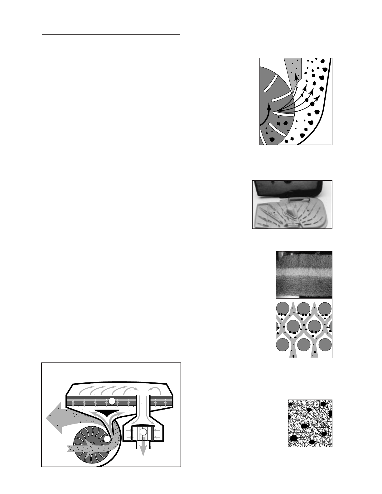
1. Centrifugal force is the first stage in cleaning the
intake air of the K950/K1250 Active. Centrifugal cleaning
was previously only used on larger engines in dusty
environments, for example for construction machines
(cyclone air filter).
The fan vanes on
the flywheel supply the
cylinder with cool air at
the same time as they act
as the active part of the
centrifugal filtering sys-
tem for the engine’s in-
take air. An intake nozzle
is fitted just beside the
fan vanes. Under centri-
fugal force, the larger
particles do not follow
the curved current of air
to the nozzle but are in-
stead thrown against the outside of the nozzle. Only very
small dust particles will be able to follow the current of
air leading into the intake. Tests show that up to 80% of
all dust is removed by the centrifugal cleaning process.
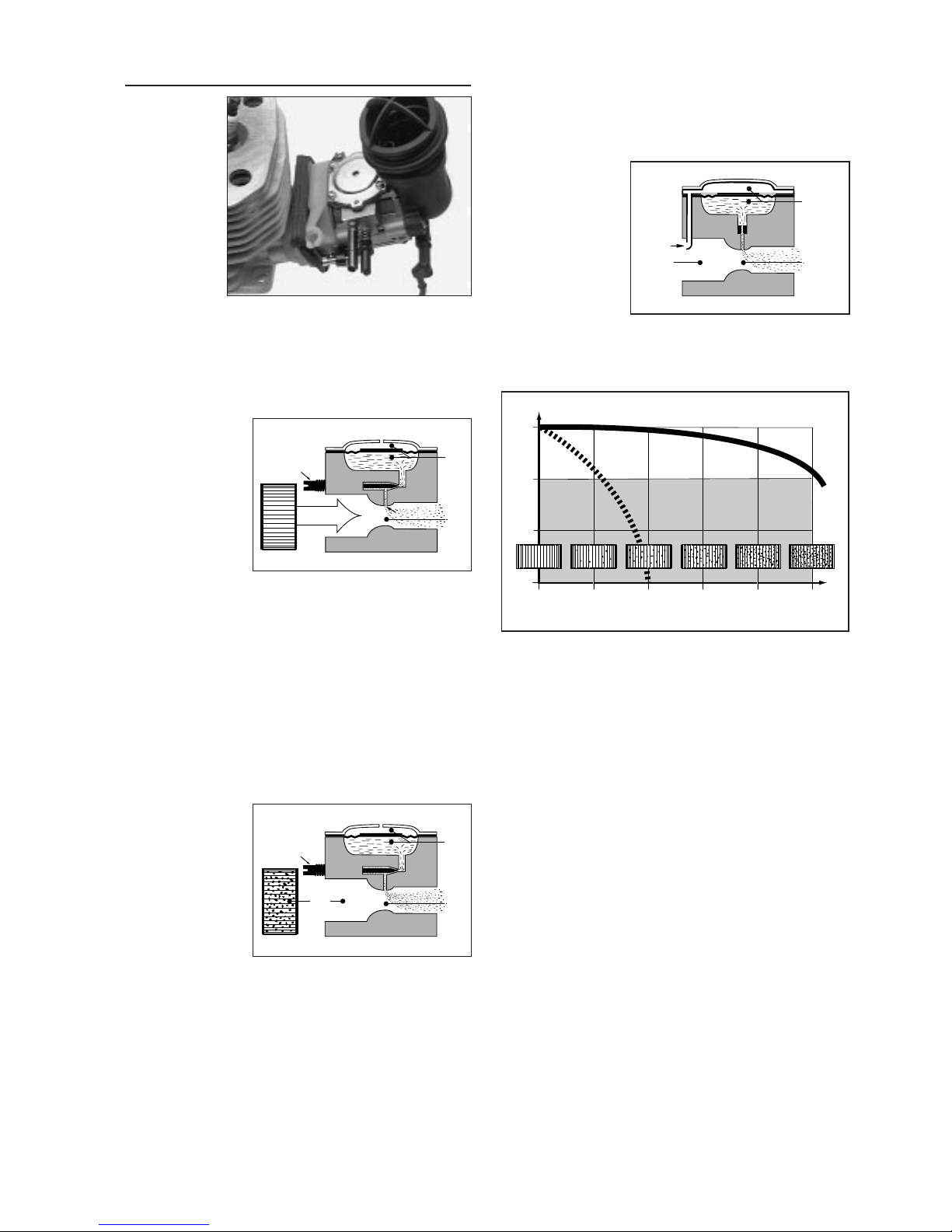
2. The foam filter
is the next stage of
separation in the filtra-
tion process. This filter
covers the housing’s
entire surface, thus
offering a filter surface
of no less than 3.5 dm2
(K950), 3.7 dm2(K1250). The filter’s base distributes air
across the entire filter surface, so the filter performs
uniformly.
The filter is immersed in oil
and is made up of three layers,
each intended for a different
pore size.
Inside the filter, the air flows
through a structure pretty much
like a labyrinth. Dust particles
which strike against the filter
sides do not bounce off but
instead fasten to the sticky oily
surface. A dry foam filter offers
far less efficient cleaning perfor-
mance than an oil-soaked filter.
An oiled foam filter is by far
the most effective filter for clea-
ning of stone dust, since the
entire filter volume is used as a
“dust trap”, not just the surface. The total dust-absor-
bing filter area is accordingly enormous. The foam filter
absorbs about 95% of the total dust volume remaining
after centrifugal filtering. It can be washed clean and
must be oiled at each service.
3. The paper filter deals with the
small amount of dust particles which,
more by chance than anything else,
may manage to slip through the foam
filter. Only a tiny amount of extremely
small dust particles will ever get as
far as the paper filter. The filter’s
dense network of cellulose fibres
traps all incoming particles. The paper filter also serves
as a protective barrier during filter services. The paper
filter should be changed at every service.
2
Filter System
Cutting in stone and concrete generates tiny dust parti-
cles which must at all costs be prevented from entering
the engine. The design of the air filter and its maintenan-
ce are the two most important factors governing the ser-
vice life of the cutter. Designing a good air filter system
is a matter of balancing effective filtering with long ser-
vice intervals.
The development of more efficient filters has improved
air-cleaning performance, but service intervals have by
tradition still been inconveniently short in cutting machi-
nes. Machine rental firms inherit the problems caused by
customers who do not carry out the necessary service
during the rental period, or are faced with the cost of tra-
velling frequently to various work-sites to carry out the
necessary service.
Dust consists of extremely fine particles, generally so
small that the individual particle cannot easily be disting-
uished by the naked eye but which in larger quantities
can be seen as a cloud of dust. The stone or concrete
dust which generally results from cutting operations
generates the most damaging kind of particles for an
engine’s sliding or rotating components. Together with
oil, this dust forms a perfect grinding paste which quick-
ly wears down pistons, piston rings, cylinder walls and
engine bearings once it penetrates an engine.
We generally measure dust particles in µm (1 µm =
0.001 mm), thousandths of a millimetre, and the particle
sizes which are dealt with by the filter system generally
measure between 50 µm and 5 µm. (It takes roughly 2
minutes for a stone particle measuring 10 µm to fall 1 m
in wind-still conditions.)
One physical characteristic which is vital to the func-
tion of the Partner Active Air Filtration system is the
behaviour of dust particles in air currents depending on
particle size:
A small particle is more easily affected by a current of
air than a larger particle.
The reason for this is that small particles have a larger
surface in relation to their mass. A small particle can the-
refore be steered and guided more easily by a current of
air while a larger particle succumbs to centrifugal force
or the force of gravity.
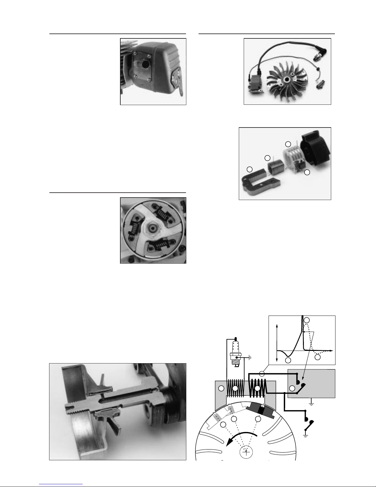
Partner Active Air Filtration is a filter system which
effectively cleans the air entering the engine in three
separate stages, utilising three different cleaning princi-
ples. The most immediate practical benefit of Active Air
Filtration is that the service intervals are far longer com-
pared to previous systems.
In
To carburettor
Cylinder
cooling air
2
3
1
Air filtration principle

Carburettor
SmartCarb™
– carburettor
with integra-
ted filter
compensation
With the
SmartCarb™
carburettor, the
machine
always oper-
ates with the
correct air/fuel
mixture, virtu-
ally irrespective of how soiled the filters are.
This design results in:
- high and more uniform engine power
- better filter economy, longer service intervals
- lower fuel consumption
- lower emissions
Carburettor oper-
ating principle
To understand the
way in which the
SmartCarb™ car-
burettor operates,
we will first de-
scribe how a con-
ventional carburet-
tor works.
The carburettor’s main job is to supply the right mix-
ture of fuel and air to the engine. Every carburettor has a
Venturi tube (A), in which the high speed jet (B) for petrol
supply is fitted. When the engine sucks in air through the
carburettor, the fuel is sucked down into the Venturi tube
and mixed with the air.
A more detailed explanation is that when the air flows
through the Venturi tube, air velocity increases, thus caus-
ing pressure to drop in the Venturi (the Bernoulli theorem).
The pressure differential between the carburettor’s fuel
chamber (P1) which operates under constant air pressure
(atmospheric pressure), and the Venturi tube’s negative
pressure (P2), causes the fuel to flow out through the jet.
Dirty filters
One problem with
the conventional
carburettor is that
the air/fuel ratio
gradually changes
as the filters be-
come increasingly
blocked with dirt.
Dirty filters in-
crease air resistance and promote a drop at (P3) which is
added to the pressure drop in the venturi (P2), so that
the pressure differential compared with the carburettor’s
fuel chamber (P1) increases. As a result, the carburettor
enriches the mixture, supplying more fuel in relation to
air, which in turn impairs the engine’s performance.
One way of compensating for dirty filters is naturally
to reduce the amount of fuel being supplied by adjusting
the high-speed needle in the carburettor.
SmartCarb™
The SmartCarb™ filter-compensating carburettor has an
air duct (C) which links the carburettor’s fuel chamber
with the intake, which is directly connected to the filter
chamber. (Note the fuel chamber’s sealed lid and the
fixed high-speed nozzle.)
The air duct (C)
ensures that the air
pressure in the fuel
chamber (P1) and
the filter chamber
(P3) remains con-
stant at all times.
Only the pressure
drop created by
the venturi tube
(P2) determines the amount of fuel which is to be mixed
with the intake air. Therefore, irrespective of whether the
filter system is clean or dirty, the relationship between air
and fuel will remain constant at all times.
The above diagram (showing a laboratory test) demon-
strates the considerable effect of SmartCarb™ on engine
power. Air pressure is measured at the carburettor’s inlet
and the figure 0 is set for brand-new filters and with the
engine running at normal speed. As the filters accumu-
late dirt, the pressure drops owing to the increased
build-up of air resistance.
At a pressure drop of just 100 mm Vp, the standard
carburettor provides such a rich fuel/air mixture that the
filters must be replaced or the H-needle has to be
adjusted. The SmartCarb™ carburettor offers excellent
engine performance all the way to 500 mmVp.
With the standard carburettor, the engine loses power
mainly because it is having to work with the wrong
air/fuel ratio, while the power drop with the SmartCarb™
– which only becomes apparent once the filters are
severely polluted – stems from the fact that the engine
receives less air and fuel owing to the air resistance
caused by the blocked filters.
Long service intervals
In practical terms, the pressure drop in the diagram can
be translated into corresponding operation times, where
we can see that the SmartCarb™ engine offers many
times the standard operating duration between filter
service!
H-needle P
1
P3P
2
C
P
1
P
3P
2
60
80
100
0 100 200 300 400 500
Pressure drop over filter (mm water)
Power %
Intake air
H-needle
AB
P
1
P
2
3

Vibration and heat-insulated carburettor
Every engine gives off a certain degree of vibration. The
carburettor has a number of moving parts such as the
control valve with its lever and diaphragm and the car-
burettor’s throttle spindles. Their function is affected by
vibration, with the effect growing in proportion to the
mass (weight) of the parts. (Light parts have a greater
ability to follow vibration-induced oscillation than do
heavy parts.)
The carburettor and its moving parts are larger in large
machines, so the K950
and K1250 Active
feature a vibration-
damping element
between the cylinder
and carburettor.
This element also
serves as a heat in-
sulator and prevents
the formation of
vapour in the carbu-
rettor.
Decompression valve
Large engine offers
relatively high resis-
tance at the starter
cord. The decom-
pression valve
solves this problem
in a simple and effi-
cient way.
When starting the machine, the valve is first opened
by pressing the button. When the operator pulls the star-
ter cord, most of the compression pressure exits through
the valve and the starter cord’s
movement is both gentle and
even. As soon as combustion
takes place in the cylinder, the
valve is shut automatically by
the combustion pressure and
the engine operates normally.
Cylinder/piston
The Partner K950 Active and K1250 Active have special-
ly developed air-cooled two-stroke engines running on
unleaded 95-octane petrol. They are lubricated with oil
mixed in the petrol.
There are two
types of flushing
duct - open and
closed. Large two-
stroke engines work
more efficiently with
closed flushing
ducts, which is why
the K950 and
K1250 Active
feature this system.
The cylinder bore is hard-chromed. The piston has two
piston rings, and it has needle bearings at the coupling
with the connecting rod.
The cylinder and piston are made in a way which
ensures ideal dimensions during operation. The piston is
profile-turned and the cylinder is honed for the tempera-
ture — and the accompanying material thermal expan-
sion — which each part of the cylinder and piston expe-
rience during operation. For example, the piston, when
seen from the side, has a somewhat barrel-shaped profi-
le, while the view from above reveals a slightly asymme-
trical oval shape.
This design gives the engine maximum power through
perfect sealing in the cylinder chamber allied to mini-
mum frictional loss against the cylinder wall. However,
this production method is both complex and expensive.
Starter unit
The Dura Starter is a new patent-pending starter unit
designed specifically for the dusty operating conditions
in which cutting machines are used. The Partner K950
Active is the largest machine to feature Dura Starter.
Dura Starter — new dust-excluding design
The principle of the new starter unit is that the pulley is
protected from vibration-induced movement. This makes
it possible to fit a series of seals and a grease-lubricated
bearing.
The spring above the pulley exerts a tensioning force
against the centre screw and acts as a brake on vibra-
tion-induced movement. An O-ring above the spring pre-
vents dust from penetrating into the pulley’s bearing. The
spacer sleeve around the centre screw is the pulley’s
upper bearing point and the entire pulley is journalled in
a slider bearing against the starter casing’s bearing pin.
The space between the pulley and the spring cassette
is shaped like a circular labyrinth, which prevents dust
from moving towards the centre. The spring cassette is
sealed against the
centre with a spring-
loaded sealing lip
lying against the
pulley.
4
Return spring
Sealing lip Spring
O-ring
Starter cord
Spring cassette
Pulley
Starter casing
Journal bearing
K950 Active K1250 Active
Open Closed

Ignition system
The ignition sys-
tem is complete-
ly sealed and has
no moving parts.
It is insensitive to
moisture and
dirt. It is desig-
ned so that the
ignition point
never needs to
be adjusted.
The Partner K950 and K1250 Active feature a built-in
over-revving protector in the electronic module, limiting
engine speed to 9,750 rpm.
The ignition
system con-
sists of the pri-
mary coil (A)
and the secon-
dary coil (B),
both of which
surround the
iron core (C).
A transistorised
electronic mod-
ule (D) deals
with the contact-breaking function.
Current is generated in the primary coil when the fly-
wheel’s permanent magnet passes the coil and produces
the voltage sequence shown in the diagram below.
(The dotted line shows the voltage which is generated if
the current is not broken.)
The ignition point is determined by the electronic
module which senses variations in voltage in the primary
coil and cuts the current at the right level, at the same
time as the piston is just below top dead centre. At the
instant that the contact is broken, voltage in the primary
coil rises from 5 V (volts) to about 200 V through a pro-
cess of induction.
In the secondary coil, a high tension of about 20,000
volts is conveyed to the spark plug.
Silencer
The silencer is of the single-
chamber type and the
exhaust gases are directed
towards the side – away
from the operator. The
panel between the cylinder
and carburettor cools the
exhaust port.
Most of the sound from
the machine comes from the
escaping exhaust gases.
The air filter system acts as an effective intake damper
and goes a long way to reducing sound pressure since
the intake air is not drawn from above the engine. Sound
levels are measured according to the CE norm in two ways:
– Sound pressure, measured at the operator’s ear.
– Sound level, the mean value of the acoustic power
which the machine generates, measured at twelve points
around the machine on a reflective flooring material
(concrete). These measurements are taken at idling
speed and maximum speed.
See the technical specifications on page 11.
Clutch
The clutch located between
the engine and the cutter is
of the centrifugal type. At
idling speed, the clutch
shoes are held against the
centre by a spring. This
means that the cutter disc
is at a standstill when the
machine runs at idling
speed. As the engine in-
creases speed, the spring
can no longer hold the shoes in place, and the shoes are
pushed against the clutch drum by centrifugal force.
Engagement speed is about 3400 rpm. At normal oper-
ating speed, centrifugal force is so high that a sudden
overload on the cutter disc will cause the belt to slip
against the pulley.
Self-lubricating clutch bearing
The clutch bearing on the K950 and K1250 Active is
lubricated automatically – a tried and tested Partner
speciality. A duct in the crankshaft opens out at the
clutch bearing. The over-pressure which is created in
the crankcase is transferred to the clutch bearing and
keeps the bearing clear of incoming dust particles and
at the same time lubricates it.
5
Electronic
circuit
breaker
STOP
control
Volts
+
-
0
Ignition
point
SN
SN
1
1
ADBC
2
2
3
3
A
B
CD
Ignition system
principle

6
Machine body
The machine body is cast in magnesium alloy for high
strength and low weight. The block is conventionally
split into two crankcase halves.
The Partner K950 and K1250 Active feature an innova-
tive machine-body construction. The machines feature a
separate vibration-damped unit encompassing the fuel
tank, rear handle and machine base plate, to the front of
which the handle arch is attached. As a result, the mass
of the handle system is greater, which in turn reduces
vibration levels. Separation of the fuel tank from the
engine body keeps the fuel cool, eliminating disruptions
caused by vapour formation in the fuel system.
Ergonomic design
The K950 and K1250 Active are noted for the clean, slim
lines of their engine bodies and the absence of protru-
ding parts — all so the operator can work as comforta-
bly and safely as possible.
In normal cut-
ting operations,
the machine is
moved straight
back and forth
in the cutting
groove, and the
operator is
close to the
machine — in
some jobs even
maintaining
direct bodily contact with the machine. Protruding parts
on the machine body may easily force it off its intended
cutting line if the machine comes into contact with the
operator or an adjacent object. This is naturally a source
of irritation and may even constitute a safety hazard.
So Partner cutters owe their clean lines to functional
requirements — with the added bonus of an attractive
appearance.
Slim machine body
Both the K950 Active and the K1250 Active feature a
machine body with minimum width, placing the centre of
gravity near the operator. This property is of utmost
importance to operating comfort and when carrying the
machine.
Surface treatment
The machine body is powder-painted, which means that
no solvents are used. Powder paint is sprayed onto the
machine body, which is electrostatically charged, to pro-
duce a uniform coating which penetrates everywhere.
The parts are then baked in an oven and the powder
paint melts to form a thick surface layer which is durable
and resistant to mechanical wear.
Crankcase bearing
The crankcase has sturdily dimensioned ball-bearings.
These are lubricated by the two-stroke oil mixed in the
fuel. The crankshaft’s sealing rings can be replaced from
outside the machine.
Crankshaft/
connecting rod
The crankshaft and
connecting rod are
forged and case-har-
dened to ensure top
strength and durabili-
ty. The connecting rod
has needle bearings
on the crankshaft.
Fuel tank
The fuel tank is integrated with the vibration-damped
handle unit, thus minimising heat transfer from the
crankcase.
Tank volume is sufficient for about 25 – 30 minutes of
operation.
Fuel filter
The pick-up, which also has a fuel
filter, always remains at the bottom
of the tank so the cutting machine
is always assured of its supply of
fuel irrespective of the angle of
operation.
The filter design is new. It is
made of sintered polyethylene
plastic which filters out the smal-
lest particles. Its high filtration efficiency reduces wear
on the carburettor’s moving parts. The filter surface is
smooth and repels dirt. The filter-replacement interval
has thus been increased several times over.
Refuelling
The Partner designers have chosen to position the fuel
filler in line with the machine body so as to avoid protru-
sions which may get in the way during cutting opera-
tions. The tank cover hangs securely from the machine
during refuelling.
In order to
avoid spillage
for environmen-
tal and safety
reasons while
refuelling, we
recommend the
type of fuel-can
which features
an overfill valve.

7
Handle system
Ergonomics have top priority in the design of every
Partner cutter. In practical terms, this means the
machine must be comfortable and safe to use. A well-
built tool will not tire or burden its operator. More work
gets done and the risk of injuries is minimised, both in
the long and the short term.
The distance between the handles is important for
overall ergonomics. A short gap means the operator
must use greater force to advance and hold the machine
on course. If the distance is too great, the machine is
difficult to control.
The ideal
distance, as on
the K950/K1250
Active, corres-
ponds closely to
the shoulder
width of the
user.
Handle grips in line with the
cutter blade
A design in which the line of grip
on the front and rear handles is
aligned with the cutter blade,
gives the best conditions for safe
and efficient cutting. The cutter
blade is automatically pressed
straight down into the cutting
groove, and the cut is straight.
Crooked cutting grooves waste
power and impose extra wear on
the cutter’s frame and segment.
Horizontal cutting is more difficult compared to the
more common vertical cutting. In vertical cutting, most
of the machine’s weight is exerted on the object being
cut and the feed pressure is applied on the front handle.
In horizontal cutting, however, the operator has to
support the machine. The front handle’s forward-positio-
ned grip in the horizontal position shifts the weight to the
rear handle, thus creating better balance. The operator
can easily and comfortably provide feed pressure with
his body against the air filter housing, with the support
of the handle arch.
Vibration suppression
In prolonged use, vibrating handles cause injuries to the
blood vessels in the hands (TVD, often termed “white
fingers”). In brief use, vibration results in impaired sensi-
tivity and muscle strength in the hands which, apart from
the discomfort, also heightens the risk of accidents.
Suppressing vibration in the handle system is some-
thing of a designer’s balancing act. A firm handle system
would, in theory, provide perfect contact and control of
the machine, if we disregard the harmful effects of vibra-
tion. Maximum vibration suppression, on the other hand,
would permit considerable movement between handle
and machine which would result in poor control over the
machine during cutting. A good handle system is always
a matter of combining optimum vibration suppression
with good control over the machine.
New design
The K950/K1250 Active differ from other Partner cutters
in that the handle unit is integrated with the fuel tank and
base plate, at the front of which there is a vibration-
suppression element. With this design, weight has been
transferred to the handle system. The greater mass in
the handle unit considerably cuts vibration levels, parti-
cularly in the case of high-frequency vibration.
The four damper elements consist
of steel springs with a rubber
damper pad at the handle arch.
The dampers are placed as far
from each other as possible, thus
achieving a good compromise
between vibration suppression
and operating convenience.
Safe starting position
The rear handle
on Partner cutters
is designed to
accommodate a
large boot, ideal
for locking the
machine in a safe
starting position.

Controls
The basic principle behind the controls needed while the
machine is running is that the operator should not need
to release his grip on the handle. Therefore, all the con-
trols are gathered together on the rear handle – for both
safe and comfortable operation.
The size and the shape of the controls make them
easy to operate with thick gloves on – gloves should
always be used for cutting operations.
Throttle control
The throttle control has
been thoroughly tested.
The spring-loaded counter-
balance, its stroke, design
and precise positioning are
all optimised for best
“finger-tip comfort”.
Throttle trigger lockout
The throttle control is block-
ed in the idling position – a
safety device to prevent
accidental acceleration. The
inhibitor, on the upper face
of the handle, is released
when the driver grasps the
handle.
Starting throttle catch
The throttle control can be
locked in a partially open
setting which ensures the
correct throttle opening for
starting, with either a cold
or warm engine. As soon as
the throttle control is pres-
sed, the catch is released.
Choke
On the K950/K1250 Active,
the choke control is pulled
outwards, a more easily
noticeable indication that
the choke is engaged. The
choke control does not act
on the throttle shutter;
instead, the partial-throttle
setting is governed by the
starting throttle catch during
start-up.
Stop control
The stop control can be
operated with the thumb
without the operator having
to release the handle. The
control cuts the ignition.
8
Cutting unit
Belt drive
The cutter blade on the K950/K1250 Active, as on most
other Partner cutters, features one drive belt leading
from a pulley on the crankshaft to the pulley on the
spindle shaft. This design has the multiple advantages of
simplicity, reliability and low weight.
It is also important from the safety viewpoint. If the
cutter blade comes to a sudden stop, the drive belt will
slip and allow the engine to come to a halt more slowly.
The cutter arm is split to permit convenient belt replace-
ment and adjustment of belt tension.
Fully sealed transmission casing
Large machines like the K950 and K1250 Active are
often used for wet-cutting operations. Water on the belt
functions as a lubricant but also increases the risk of
belt slip. These machines are therefore equipped with a
sealed casing that prevents
water from reaching the belt.
Dust is also kept away from the
belt, thus reducing wear. In order
for the transmission to be suffici-
ently cooled, the casing features
cooling-air vents at the clutch.
Semi-automatic belt tensioning
Opinions as to what is the “correct” belt tension vary
from one operator to another. Partner’s semi-automatic
belt tensioning system solves this problem – a standard-
ised spring provides the correct tensioning force.
In precisely controlled experiments in the laboratory,
Partner has computed the optimum belt tension which
gives the belt maximum service life allied to perfect
application pressure before it slips against the pulley.
Belt tension
has to be ad-
justed occasion-
ally owing to
stretching and
wear of the belt.
This is done
quickly in three
stages.
Drive belt
The drive belt in a cutting machine is subjected to se-
vere and uneven loads and sometimes also to immense
load peaks. The drive belt also operates on relatively
small-diameter pulleys, which imposes particular
demands on the belt. To the naked eye, original-specifi-
cation Partner belts may look like any other drive belt,
but they are specially designed for their specific func-
tion. The belt-tensioning rating, which is determined by
the adjustment spring, is tested using genuine Partner
belts.

Blade guard
The blade guard is by far the machine’s most important
safety feature. The normal task of the blade guard is to
direct cutting dust away from the operator, but it must
also stand up to the effects of a malfunctioning blade.
The blade guard is made of steel plate, with its thickness
doubled at the periphery.
Self-adjusting blade guard
The blade guard is of a
new design. Instead of
fixed settings, it features
a friction lock which auto-
matically adjusts the posi-
tion of the guard to suit
current operating
settings.
Generally, the rear edge of
the blade guard should rest
on the object being cut. The
effect of this is that the par-
ticles follow the path created
by the guard and are ejected
ahead at relatively low
speed.
Wet cutting
Wet cutting vir-
tually eliminates
cutting dust
and the blade is
cooled at the
same time,
which in turn
prolongs the
blade’s service
life.
The blade
guard is facto-
ry-prepared for
attachment to
Partner’s wet
cutting kit.
The wet cut-
ter adapter has
been redesigned and is quickly fitted in place. The nozz-
les are fitted on simply to the blade guard with a screw
on the outside securing them in place. The control on
the handle arch is used to regulate the volume of water
delivered to the cutter blade. The supply hose is now
equipped with a standard Gardena®quick-release
coupling.
Simple blade replacement
The blade guard has a
generous cut-out to aid
blade replacement. This
opening also gives the
operator a clear view of
the working surface during
cutting.
Rotation-inhibited flange
washers
Both the inner and the outer
flange washers are locked in
place against the spindle shaft
so they cannot rotate. The dual
connecting flange locks the
blade in place securely, even if
the lock-screw is only tighte-
ned moderately. This design
also prevents undesirable self-tightening. As usual, the
lock-screw is right-threaded and features a permanent
washer.
Replaceable blade bushing
Partner cutting machines can be equipped with centre
bushings to suit various standards. Replaceable centre
bushings are available for diameters of 20.0 mm, 22.2
mm, 25.4 mm (1”) and 30.5 mm. The Partner K950/
K1250 Active are supplied as standard with different
centre bushings to suit the market on which they are sold.
9
Reversible cutter arm
The cutter arm can be
reversed. This makes it
possible to cut close to a
wall or at floor height with
the blade guard as the only
limiting factor, in other
words about 20 mm from
the cutter blade. Naturally,
some of the machine’s
ergonomic benefits are lost
when the cutter arm is
reversed, but the ability to
carry out certain operations
may in fact depend on this
feature.

Peripheral speed
Peripheral speed is measured in
metres per second and is directly
proportional to engine speed. By
definition, peripheral speed is the
speed at which a given point on
the blade’s circumference travels
through the air. It is also the
speed which a given diamond
segment, for instance, has in relation to its point of con-
tact during cutting. Another way of looking at the term
“peripheral speed” is to imagine a cutting machine as a
moving vehicle with the cutter blade as the driven wheel.
A speed of 5,100 rpm with a 300 mm cutter blade would
give the following speed:
Blade circumference: 0.3 m ×π= 0.94 m
Blade speed: 5,100 rpm = 85 r/s
Circumference ×speed = peripheral speed
Peripheral speed = 0.94 m ×85 r/s = 80 m/s
Computed into a “vehicle-type situation” this gives a
speed of about 290 km/h!
Partner cutter blades are made for peripheral speeds
of 100 m/s. A European colour code prescribes a green
colour for a maximum peripheral speed of 100 m/s,
while a red colour indicates max. 80 m/s.
BLADE TYPES
Hand-held
power
cutters require
cutting blades
which are
approved for
use in hand-
held machines
– it is not per-
missible to fit
them with bla-
des intended
for fixed-posi-
tion bench-
mounted machines, for example. The speed marking
must match or be higher than the figure on the machine’s
specification plate. Partner cutting blades are naturally
intended for Hand-held cutting.
– The diamond blade is becoming increasingly common
for cutting concrete, stone, asphalt and similar materials.
The general advantage of the diamond-tipped blade is
that it retains its cutting depth virtually throughout its life
so cutting efficiency remains high. Used correctly, it
offers excellent blade economy.
Partner “PowerCut” diamond blades are available for
professional and occasional users. The range encom-
passes several grades which are selected to suit the
type of material to be cut. Diamond blades are available
for both dry and wet cutting.
– Abrasive discs, which used to be the norm for cutting
all materials, are now used primarily for cutting metals.
Partner abrasive blades are available for steel and conc-
rete, the concrete blade is also very suitable for cutting
softer steel types such as reinforcing rods and structural
steel.
– Partner Rescue is a special blade with a TCT hard-
metal cutter. It may only be used by specially trained
personnel in emergency rescue situations.
10
Cutter blades
Specification plate
All Partner power cutters
are equipped with a plate
on the blade guard which
details all the important
specifications needed for
choosing cutter blades.
The dimensions which
the operator needs to
know are the following:
Blade diameter
Blade diameter is given in either
mm or inches.
Three models are available in
the Partner K950 Active range,
with cutting blade sizes 300 mm
(12˝), 350 mm (14˝) and 400 mm
(16˝). Two Partner K1250 Active
models are available, with 350
mm (14˝) and 400 mm (16˝) cutting
blades respectively.
Centre diameter
The cutter blade’s fitting holes
must exactly match the bushing
diameter on the spindle shaft.
Various standards are available
depending on the countries in
which the machines are sold.
The most common standards are
20.0, 22.2, 25.4 (1˝) and 30.5 mm.
Bushings for Partner Power Cutters
are available for these diameters
and can be replaced.
Speed
All cutter blades are marked
with a speed which is usually
measured in revs per minute
(rpm) and which indicates the
rotating speed which should not
be exceeded. The blade’s maxi-
mum speed is determined by the
blade manufacturer.
The Power Cutters plate also indicates a speed which
is determined by the machine manufacturer and which is
termed the “nominal speed”.
The nominal speed is the speed which is stated on the
machine plate and which determines which marking the
blade must have in order to be used with the machine.
The cutter blade should be marked with the same or
higher speed than that specified on the machine plate.
The maximum speed of the machine is a rating which
does not affect the machine operator, so it is not speci-
fied on the machine but it is used, for instance, as a
control parameter at the service workshops. The maxi-
mum speed is the highest permitted speed which the
spindle shaft is allowed to achieve with an unloaded
blade and the engine running at full throttle.
According to the European norm, the maximum speed
may not exceed the nominal speed specified on the
machine by more than 10%. For example, a machine
with the nominal speed of 5,100 rpm should never
exceed a max. speed of 5,100 ×1.1 = 5,610 rpm.
rpm
m/s

11
Engine
K950 Active
Air-cooled, 2-stroke 94 cm3
Power 4.5 kW
Bore/stroke 56 mm/38 mm
Compression ratio 10.0:1
K1250 Active
Air-cooled, 2-stroke 119 cm3
Power 5.8 kW
Bore/stroke 60 mm/42 mm
Compression ratio 10.0:1
Fuel
Petrol, min. 90 octane unleaded (green pump)
Oil mixture 4% (1:25)
Oil mixture with Partner-oil 2% (1:50)
Tank volume K950 Active 1.0 l
K1250 Active 1.25 l
Full tank under normal operation lasts
approx. 25–30 min.
Carburettor
K950 Active
Tillotson HS282A SmartCarb™ with built in filter com-
pensation.
K1250 Active
Walbro WG 9 SmartCarb™ with built in filter compen-
sation.
Air filter
Three filtration principles:
1. Active centrifugal filtration
2. Oil-immersed 3-layer foam filter
Filter area K950 Active 3.5 dm2
K1250 Active 3.7 dm2
3. Dry filter, folded paper filter 16 dm2
Ignition system
Transistorised ignition system, Electrolux type
Spark plug NGK, BPMR7A or Champion, RCJ7Y
Electrode gap 0.5 mm
Clutch
Centrifugal clutch with 3 clutch shoes.
Engagement speed, min. 3,200 rpm
Automatic lubrication of clutch bearing.
Blade guard
Made of steel. Self-adjusting.
Blade bushing
Replaceable centre bushing for hole diameters:
20.0 mm, 22.2 mm, 25.4 mm (1˝) and 30.5 mm.
Transmission
Belt type V-belt
Sound level
K950 Active
Pressure 102.6 dB(A)
Power 111.7 dB(A)
K1250 Active
Pressure 102.0 dB(A)
Power 114.6 dB(A)
Vibration levels
K950 Active
Idling, front/rear handles 8/9 m/s2
Full throttle, front/rear handles 6/8 m/s2
K1250 Active
Idling, front/rear handles 7/7 m/s2
Full throttle, front/rear handles 5/6 m/s2
The CE marking indicates that the
manufacturer guarantees that the machine
meets all the requirements of the EU direc-
tives, that is to say those safety standards
which must be met in order for the machine
to be sold within the EES block.
K950/12˝ K950/14˝ K950/16˝ K1250/14˝ K1250/16˝
Cutting blade, diam. 300 mm (12˝) 350 mm (14˝) 400 mm (16˝) 350 mm (14˝) 400 mm (16˝)
Cutting depth 100 mm (4˝) 125 mm (5˝) 145 mm (6˝) 120 mm (5˝) 145 mm (6˝)
Nominal speed, blade spindle 5,400 rpm 5,400 rpm 4,700 rpm 5,400 rpm 4,700 rpm
Transmission ratio, engine/spindle 1/0.52 1/0.52 1/0.42 1/0.51 1/0.47
Dimension with blade:
Length 765 mm 790 mm 815 mm 865 mm 890 mm
Max. width 220 mm 220 mm 220 mm 240 mm 240 mm
Max. height 365 mm 425 mm 465 mm 440 mm 480 mm
Weight, without blade 9.9 kg 10.3 kg 11.2 kg 13.4 kg 14.3 kg
Packaging:
Dimensions carton, mm 700×240×460 700×240×460 715×240×510 780×260×510 780×260×510
Quantity per pallet 15 units 15 units 15 units 12 units 12 units
Technical specifications PARTNER K950 / K1250 Active

Partner Industrial Products
SE-433 81 PARTILLE, Sweden
Tel: +46 31 94 90 00. Telefax: +46 31 94 91 14
ARNE PALMQUIST Risbergs Tryckeri AB, Uddevalla
Other manuals for K950 Active
3
This manual suits for next models
1
Table of contents
Other Partner Saw manuals

Partner
Partner K1250 Active User guide

Partner
Partner K950 Active User manual

Partner
Partner K750 User manual

Partner
Partner K950 CHAIN Instruction manual

Partner
Partner K 3500 User manual

Partner
Partner K700 ACTIVE III Setup guide

Partner
Partner K1250 Active User manual

Partner
Partner K650 ACTIVE II EPA User manual

Partner
Partner K1200 Setup guide

Partner
Partner P340S User manual