REPLACEMENT OF CHAIN/BAR 4
7
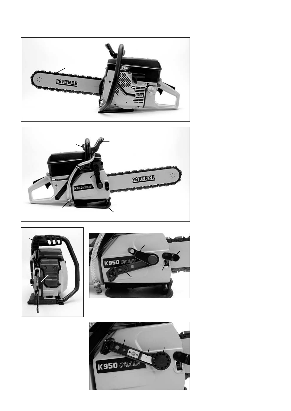
Fit the chain
Fit the bar and chain.
Fit the chain
Place the machine upright.
Place the chain in the bar and fit it
on the rim sprocket.
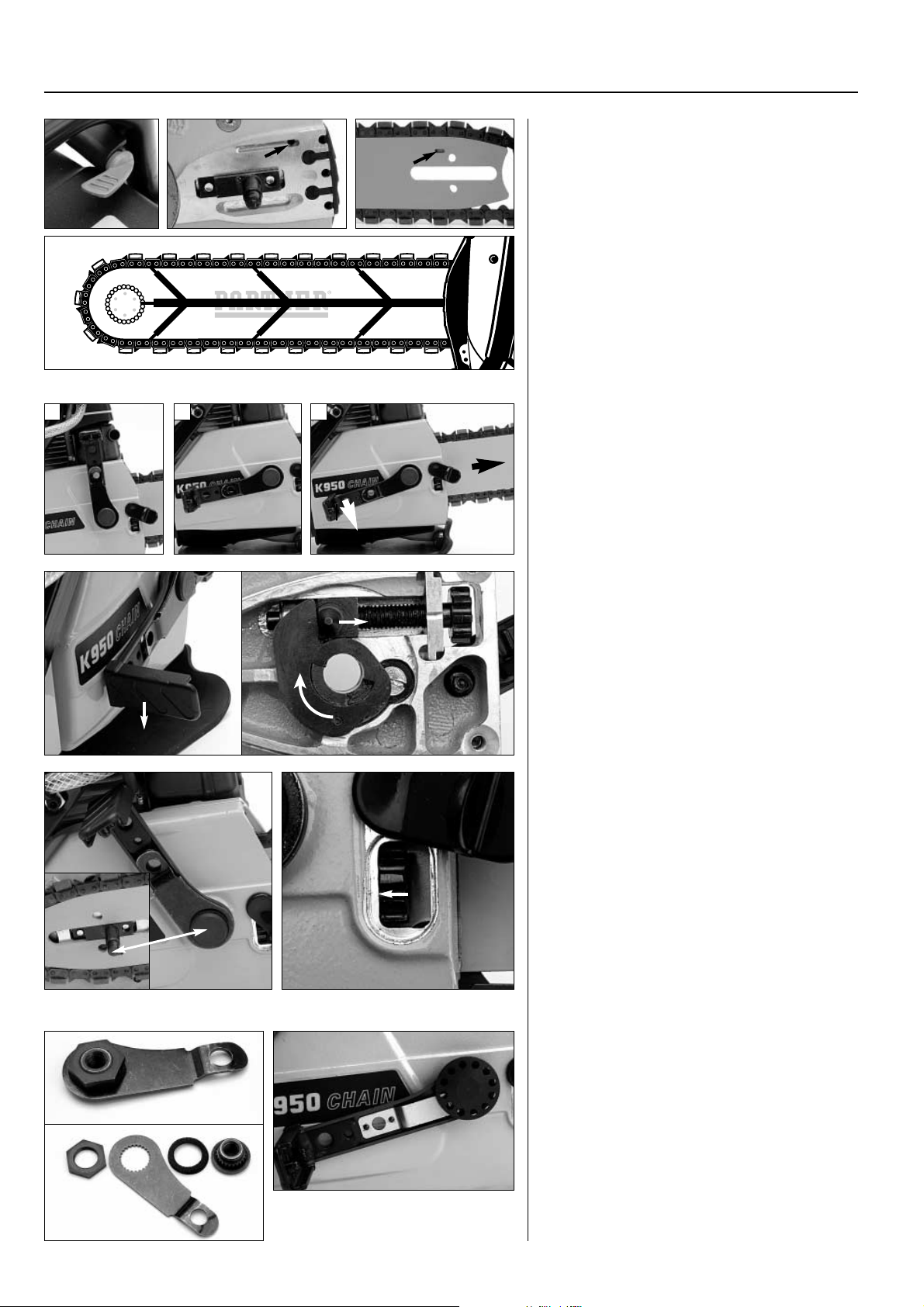
New chain
When a new chain has been fitted,
the bar tensioning lug must be
adjusted to its rearmost position.
New chain
Adjust the bar tensioning lug
to its rearmost position.
Fit the cover
Old version:
Position the cover. Fit the flange,
tighten the screws and lift into the
lever.
New version:
Press down the lock spring and fit
the castellated nut, tighten slightly.
Tension the chain as described in
chapter 5.
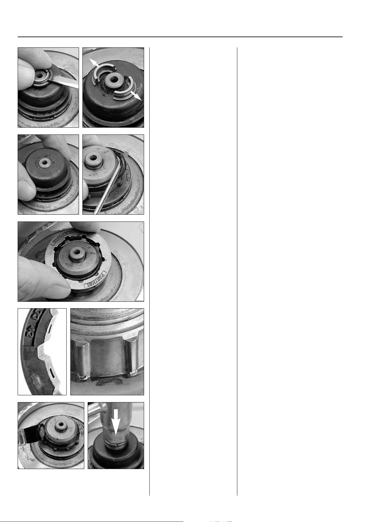
Adjust the lock-nut
When upright, the lever should lock
the bar. If the tensioning force is in-
correct, the flange nut is tightened as
follows:
Old version
1. Lift up the flange from the lever
and tighten it firmly until the bar is
securely locked.
2. Mark the nut in line with the
cover’s contour.
3. Remove the flange and undo the
nut and rubber seal.
4. Rotate the bar nut so that the
mark lines up with the arm. Fit the
seal and nut, tighten.
Adjust the lock-nut
When upright, the lever
should lock the bar. If it does
not, adjust as follows:
Old version
1. Tighten the flange until
the bar is securely locked.
2. Mark the nut in line with
the cover’s contour.
3. Remove the flange and
undo the nut at the back.
4. Rotate the bar nut so that
the mark lines up with the
arm. Fit the seal and nut,
tighten.
Fit the cover
Old version:
Position the cover. Fit the
flange and lift into the lever.
Tension the chain.
New version:
Press down the lock spring and
fit the castellated nut, tight-
en slightly. Tension the chain
as described in chapter 5.
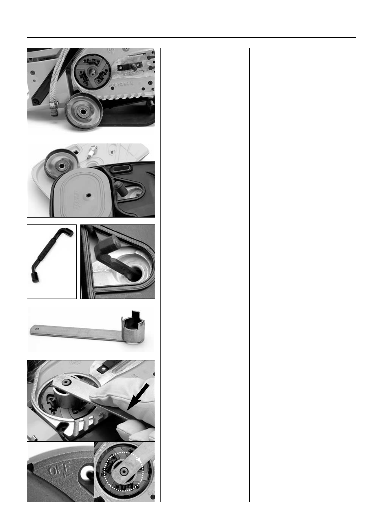
New version
Adjust the lever’s locking position
every time the cover is fitted.Press
down the lock spring (A) and tighten
the castellated nut (B). Tighten light-
ly by hand.
Check that the castellated nut is in
the right position in the lock spring
by moving the lever upward, in line
with the cover’s contour where it
should lock the bar.
If it does not, adjust the castellated
nut. Move the lever to the horizontal
position and choose another hole in
the castellated nut.
New version
Press down the lock spring
(A) and lightly hand-tighten
the castellated nut (B).
Check that the castellated
nut is in the right position in
the lock spring by moving
the lever upward, where it
should lock the bar.
1. 2.
3. 4.
Old version New version
A
B