Equipment Overview
This section provides a brief overview on how to use the equipment included with the
dynamics system. For more detailed information, see the instruction manual included
with each product.
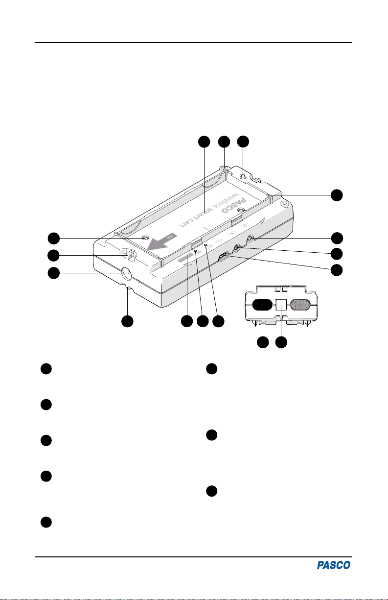
Smart Cart Features
1
Rear View
23
4
5
6
7
8
9
10
11 12 13 14
15 16
Accessory Tray
For placing accessories such as cart
masses.
1
Accessory Hole
For attaching accessories such as the
fan cart sail.
2
Plunger Release
Press to release the plunger at the
rear of the cart.
3
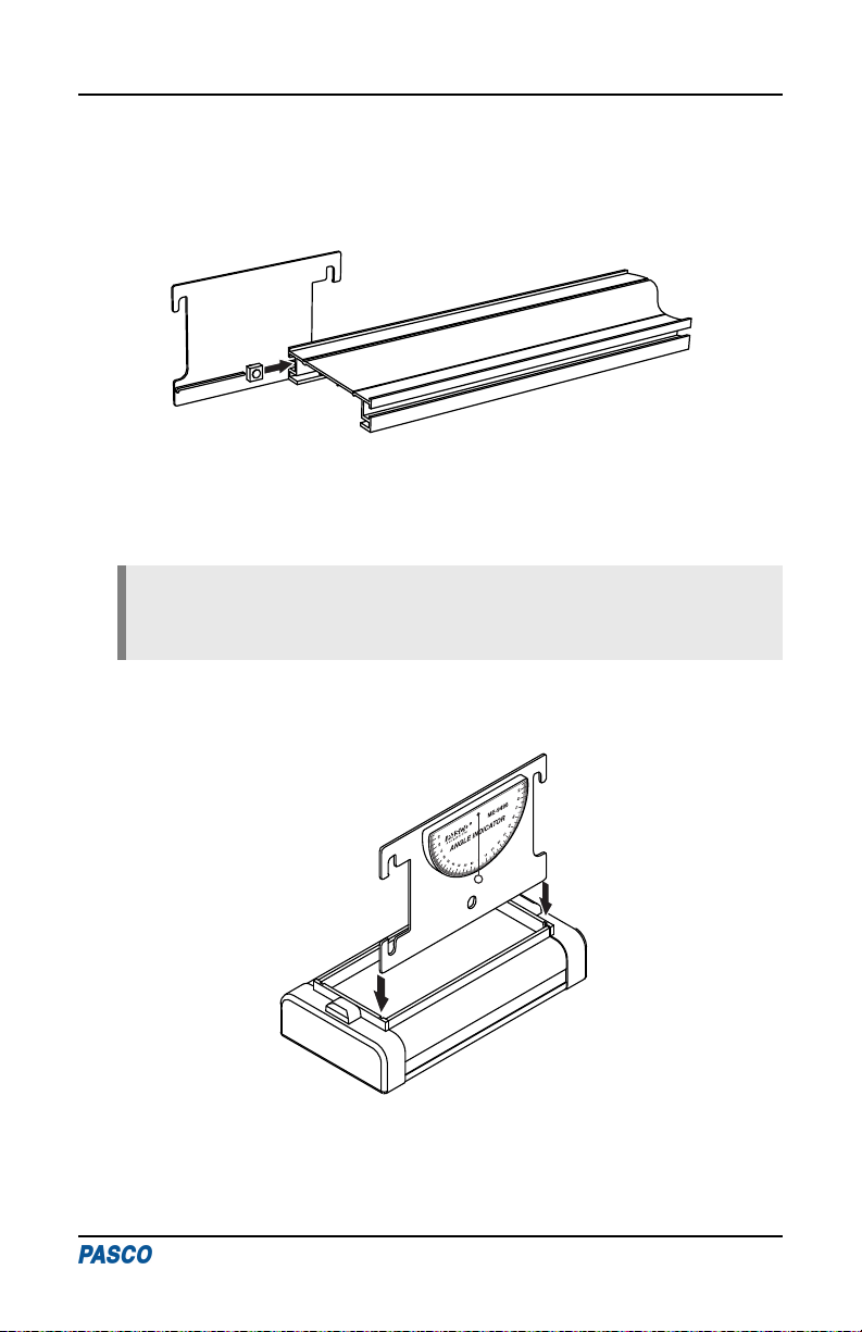
Accessory Tray Slot
For attaching accessories such as a
Cart Picket Fence (ME-9804) or
Angle Indicator (ME-9495A).
4
Power Button
Press and hold for one second to
power the cart on or off.
5
Accessory Port
For connecting Smart Cart
accessories such as the Smart Fan
(ME-1242), Smart Ballistic Cart
(ME-1245), and Vector Display
(ME-1246).
6
USB Port
For charging the battery by
connecting the cart to a USB charger
or the Smart Cart Charging Garage
(ME-1243).
7
Threaded Hole (M5)
For securing accessories in the tray
such as the Smart Cart Rod Stand
Adapter (ME-1244).
8
Standard Smart Cart PAStrack System | ME-5717A
2