PASCO TD-8577 User manual

Instruction Manual
012-13028C
PASCO Compression Igniter
TD-8577
®
P
i
s
t
o
n
S
t
a
r
t
i
n
g
P
o
s
i
t
i
o
n
Outer Safety
Tube
(polycarbonate)
Piston
Removable
Base
Bottom
Removable Top
Knob
Loading/Cleaning
Rod
“O” rings “O” rings
Replacement
Glass Tube
Small O-ring (4)
Inner Glass
Tube
Medium O-ring (1)
IMPORTANT!
Piston Starting
Position label
Large O-ring (1)
Replacement
O-rings (6)

PASCO Compression Igniter 012-13028C Introduction
®
2
* The TD-8498A Replaceable Glass Tubes includes two replacement tubes and twelve O-rings.
Introduction
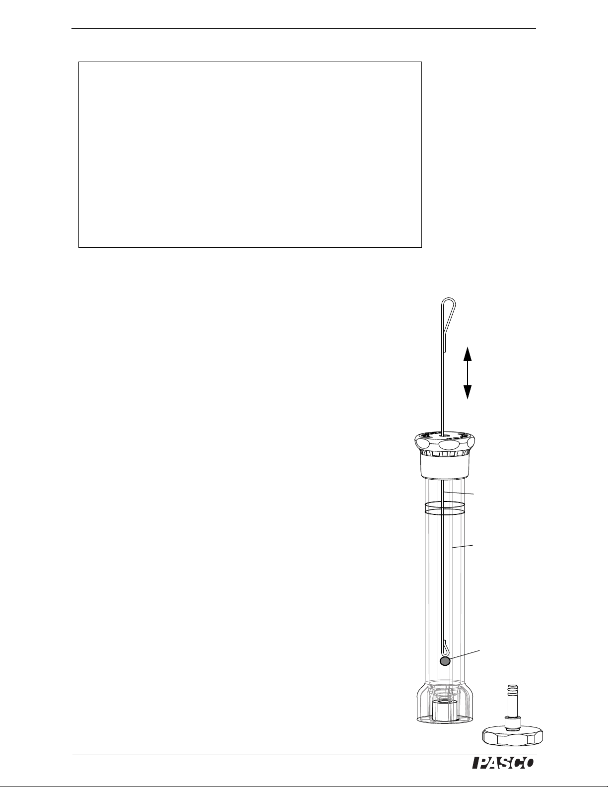
The TD-8577 PASCO Compression Igniter (or “fire syringe”) illustrates what hap-
pens inside the cylinder of a diesel engine. It demonstrates the high temperatures pro-
duced during adiabatic compression of air by igniting a small amount of cotton, tissue
paper, or magician’s “flash paper” inside a replaceable, thick-wall glass tube. The
glass tube is encased in a polycarbonate safety tube that protects users from injury if
the glass tube breaks. The piston has two rubber “O” rings at its end that provide a
tight seal against the inside of the glass tube. When the piston is rapidly pressed down
into the glass tube, the temperature inside the tube rises quickly.
The Compression Igniter comes with one replacement glass tube and six O-rings. The
large O-ring is a replacement for the ring at the top of the inner glass tube. The
medium O-ring is a replacement for the ring at the top of the piston rod where it joins
the knob. The small O-rings are replacements for the rings on the end of the piston
rod and for the rings on the post that is part of the removable base.
Theory
The compression of air inside a hollow cylinder is an adiabatic process since the
compression is so fast that there is no time for thermal energy to leave or enter the
cylinder.
For an adiabatic compression of gas, , where Pis the pressure of the
gas, Vis the volume of the gas, and is the ratio of specific heats of the gas (specific
heat at constant pressure divided by specific heat at constant volume)
Therefore, when the gas in the cylinder is at its original volume V0and pressure P0
and then is compressed to a small volume Vand pressure P,
With the compression igniter, it is possible to compress the gas in the cylinder by a
factor of about 15, so V0= 15V. With this assumption, the final pressure at maximum
compression can be calculated in terms of the initial (atmospheric) pressure:
The quantity that is of interest is the final temperature: Is it high enough to ignite
paper? To arrive at the temperature, assume that the gas is air and that it is an ideal
gas. For an ideal gas,
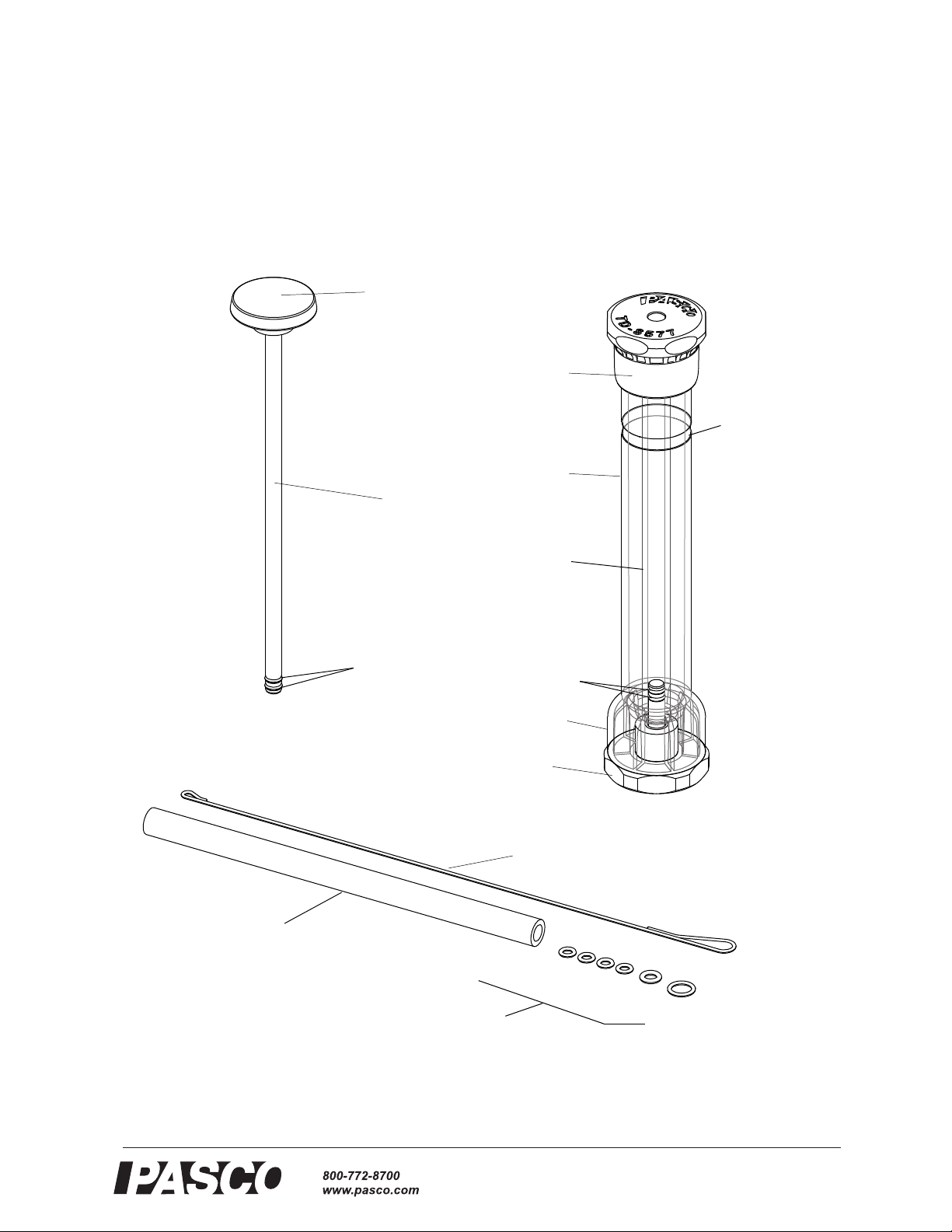
Included Equipment Included Equipment
PASCO Compression Igniter Replacement Glass Tube*
Loading/Cleaning Rod Replacement O-rings* (6)
Lubricant, silicone compound, (2 packets), not shown Material Safety Data Sheet for Lubricant
Additional Item Needed Cotton, tissue paper, “flash paper”
PVconstant=
PVP0V0
=
PVP015V
=
P15P0
=
The ignition temperature of
paper is about 451 °F.
See the science fiction
novel Fahrenheit 451 by
Ray Bradbury.
P0V0nRT0and=
PV nRT=

Model No.TD-8577 012-13028C Operation
®
3
where nis the number of moles of gas, Ris the gas constant, and Tis the absolute
(thermodynamic) temperature. Solving the initial equation for nR and substituting the
expression into the final equation gives:
Solving for the final temperature, T, and substituting the final pressure, P, derived
from the adiabatic equation and the final volume, V, which is 1/15 the initial volume
gives:
Simplifying this expression gives T= 15(- 1)T0. For air, which is mainly diatomic, =
1.4, so this gives T= 150.4T0. Assuming that the initial temperature is about 24 °C
(297 K), then T= 150.4(297 K) = 877 K. Converting to celsius, T= 604 °C. Since
604 °C = 1120 °F, the temperature is high enough to ignite paper.
Operation
1. Turn the removable base counterclockwise to unscrew it from the bottom of the
igniter. Remove the base and set it aside.
2. Insert a small piece (~ 1 cm2) of tissue paper or a few strands of cotton fiber (e.g.,
pulled from the end of a cotton swab) into the bottom of the glass tube.
3. Use the loading/cleaning rod to push the material up into the lower part of the
glass tube. Carefully remove the loading/cleaning rod without pulling the mate-
rial out of the lower part of the glass tube.
4. IMPORTANT: Insert the piston into the top of the igniter and push it in far
enough that the end of the piston lines up with or is slightly below the
“Piston Starting Position” label on the outer tube 2.5 cm (1 inch) below the top.
5. Replace the removable base by screwing it clockwise into the bottom.
6. Place the base of the igniter on a sturdy horizontal surface and securely hold the
tube with one hand. Make sure that the combustible material in the bottom of the
glass tube is visible.
7. Watch the piece of combustible material at the bottom of the glass cylinder.
8. With the palm of your other hand, quickly slap down on the knob of the piston so
the end of the piston goes down into the cylinder rapidly. Slap it down and keep
it down.
PV P0V0T
T0
----------------
=
TPV
P0V0
------------ T0
15P0V
P015V
--------------------- T0
==
P
i
s
t
o
n
S
t
a
r
t
i
n
g
P
o
s
i
t
i
o
n
Combustible
material
Piston
Push knob
down rapidly
Grip
tube
firmly
Watch
here
Piston Starting
Position label
Bottom
Top
Safety Tube
Glass Tube
Insert combustible
material here.
Removable
Base

PASCO Compression Igniter 012-13028C Caution
®
4
.Hints
Maintenance
Cleaning
To remove fragments of burned material from the igniter, unscrew the remov-
able base from the bottom of the igniter. Use the loading/cleaning rod to scrape
any residue out of the lower part of the glass tube.
To clean the glass tube, remove the piston and the base. Use the loading/clean-
ing rod to push a small wad of tissue paper through the glass tube.
After cleaning, screw the removable base back into the bottom of the igniter.
Do not use a wrench or other tool to tighten the removable base or the top.
Instead, they should be only as tight as you can make them using your hand.
Lubrication
The “O” rings on the piston and the removable base are lubricated at the fac-
tory. If the “O” rings on the piston become dry, tear or cut the tip off the packet
of lubricant. Squeeze a small drop (1 to 2 mm diameter) of lubricant onto an
applicator (such as a toothpick, cotton-tipped swab, etc.), and rub the lubricant
onto the two “O” rings. Store the open packet in a plastic bag or a small jar.
CAUTION: Do not use a different lubricant than the kind provided.
Storage
Store the compression igniter with the piston removed from the inner glass
tube.
Caution
The inner cylinder in the Compression Igniter is thick-wall glass, but it can
break if the Compression Igniter is dropped or if the piston is not far enough
down into the glass tube when the igniter is used. Before using the igniter, be
sure that the bottom of the piston is at least to the “Piston Starting Position”
label.
Be careful when handling the Compression Igniter, and always store the igniter
with the piston removed from the glass tube. The Compression Igniter is
shipped with a replacement inner glass tube packed separately to minimize the
possibility of damage during transit.
• Do not ‘clump’ or compress the combustible material. Allow it to remain
flat and spread out. The more surface area it has, the better.
• If the material does not ignite, try reducing the amount of material you put
into the glass tube.
• If you are using a piece of tissue paper, remove the paper and tear it in half.
Put one half of the paper back into the glass tube and try again.
• If you are using cotton and it does not ignite, reduce the number of strands
of cotton and try again.
• After “firing” the Compression Igniter, remove the base and move the pis-
ton up and down in the cylinder to purge (remove) any combustion gases.
Wad of tissue
paper
Loading/Cleaning
Rod
Glass
Tube

Model No.TD-8577 012-13028C Caution
®
5
Replacing the Inner Glass Tube
If the glass tube in the Compression Igniter should break, replace it with the
included replacement glass tube*.
• Hold the igniter over a receptacle to catch any falling glass and remove the
piston.
• Unscrew the removable base from the bottom, and unscrew the top from
the safety tube.
• Carefully remove any broken glass from inside the safety tube and dispose
of the glass properly.
• Check the condition of the O-rings and replace them if necessary. NOTE: If
the O-rings show no abrasion damage, they do not need replacing.
• Screw the removable base into the bottom of the igniter. Leave the top off
the igniter.
• Carefully insert the replacement glass tube into the igniter so that the bot-
tom end of the glass tube fits over the post at the bottom of the igniter.
• Replace the top on the igniter. Be careful to line up the upper end of the
inner glass tube with the hole in the top.
*The TD-8498A Replaceable Glass Tubes kit includes two more replacement tubes and
twelve O-rings
Replacing a Large O-ring
• To replace the large O-ring in the top of the igniter, unscrew the top from
the safety tube.
• Remove the old O-ring. (You may need to use a small, flat-blade screw-
driver to remove the ring.)
• Place the replacement O-ring in the groove at the bottom of the hole. Make
sure that the O-ring is flat against the bottom of the hole..
• Replace the top on the igniter. Line up the top end of the glass tube with the hole
in the top and then turn the top clockwise to screw it onto the igniter.
P
i
s
t
o
n
S
t
a
r
t
i
n
g
P
o
s
i
t
i
o
n
Safety Tube
Glass Tube
Post
Base
Insert the glass
tube over the post
and O-rings.
Top
Glass
Tube
1. Remove
the top.
2. Clear the
broken glass.
3. Insert the
replacement
glass tube.
4. Replace
the top.
Replacing a Glass Tube
Top
O-ring
installed
O-ring
Removable
Top
Top View Side View
(cutaway)
Replacing a Large O-ring into the Top

PASCO Compression Igniter 012-13028C Teacher and Technical Support
®
6
Teacher and Technical Support
For assistance with any PASCO product, contact PASCO at:
For more information about the PASCO Compression Igniter and the latest revision of
this instruction sheet, visit the PASCO web site at www.pasco.com and enter
TD-8577 in the Search window.
Limited Warranty
For a description of the product warranty, see the PASCO catalog.
Copyright
This PASCO scientific Instruction Manual is copyrighted with all rights reserved. Permission is granted to non-profit educational insti-
tutions for reproduction of any part of this manual, providing the reproductions are used only in their laboratories and classrooms, and
are not sold for profit. Reproduction under any other circumstances, without the written consent of PASCO scientific, is prohibited.
Trademarks
PASCO and PASCO scientific are trademarks or registered trademarks of PASCO scientific, in the United States and/or in other coun-
tries. For more information visit www.pasco.com/legal.
Address: PASCO scientific
10101 Foothills Blvd.
Roseville, CA 95747-7100
Phone: +1 916 462 8384 (worldwide)
800-772-8700 (U.S.)
Web: www.pasco.com
Email: [email protected]
Specifications
Inside diameter of glass
tube = 0.797 cm
Compressible length of glass
tube = 18.308 cm
Compression ratio
(approximate) = 15 to 1
Table of contents
Other PASCO Industrial Equipment manuals