Paso SE8000 Series User manual

SERIE AW8000 1
Unità di potenza
Boosters
Unité de puissance
AW8501
AW8501/117
ISTRUZIONI PER LUSO INSTRUCTIONS FOR USE MANUEL DUTILISATION
AW8000
SERIE
SERIES
TABLE OF CONTENTS
1. General description .................. 3
1.1 Front panel .....................................3
1.2 Rear panel ......................................3
2. General warnings ...................... 4
2.1 Installation .....................................4
2.2 Power supply and earthing .............. 4
2.3 Safety notes ................................... 4
3. Connections ............................... 5
3.1 General features .............................5
3.2 Line input ........................................5
3.3 Amplified stand input .......................6
- Amplified stand precedence ..........6
- Automatic precedence ..................6
3.4 Power outputs ................................7
3.4.1 Low-impedance systems ..................7
3.4.2 Constant voltage systems ...............8
3.5 Voice selection filter ......................... 9
3.6 Optional modules ............................9
- Chime module ............................... 9
- Alarm board ................................ 10
- Remote volume
control board ............................. 10
- Output
two-level control ........................ 11
3.7 Modules........................................ 11
4. Operation................................. 12
4.1 Power on ...................................... 12
4.2 Forced ventilation ......................... 12
4.3 Master volume control ................... 12
4.4 Acoustic adjustment ...................... 12
5. Service notes .......................... 13
5.1 Overload and
protection conditions .................... 13
5.2 Equipment adjustments ................. 13
6. Technical specifications.......... 14
7. List of spare parts ................... 15
SOMMAIRE
1. Description générale .............. 16
1.1 Panneau frontal ............................ 16
1.2 Panneau postérieur ....................... 16
2. Précautions générales............ 17
2.1 Installation ................................... 17
2.2 Alimentation et mise à la terre ....... 17
2.3 Conseils de securité ...................... 17
3. Connexions .............................. 18
3.1 Criteres generaux ......................... 18
3.2 Entrée de ligne .............................. 18
3.3 Entrée base amplifiée .................... 19
- Priorité base amplifiée ................. 19
- Priorité automatique ................... 19
3.4 Sorties de puissance ..................... 20
3.4.1 Systèmes à basse impédance ........20
3.4.2 Systèmes à tension constante ....... 21
3.5 Filtre selectif voix ..........................22
3.6 Modules accessoires ...................... 22
- Fiche ding-dong .......................... 22
- Fiche dalarme ............................ 23
- Fiche de contrôle
du volume à distance ................. 23
- Contrôle du niveau de
sortie sur deux niveaux .............. 24
3.7 Modules........................................ 24
4. Utilisation de l'appareil ........... 25
4.1 Mise en marche ............................. 25
4.2 Ventilation forcée .......................... 25
4.3 Contrôle de volume principal .......... 25
4.4 Correction acoustique ................... 25
5. Notices de service ................... 26
5.1 Conditions de
surcharge et protection ................ 26
5.2 Reglage de l'appareil .....................26
6. Caractéristiques techniques .. 27
7. Liste des pièces détachées .... 28
SOMMARIO
1. Descrizione generale ................ 3
1.1 Pannello frontale .............................3
1.2 Pannello posteriore .........................3
2. Avvertenze generali ................. 4
2.1 Installazione ...................................4
2.2 Alimentazione e messa a terra .........4
2.3 Note di sicurezza .............................4
3. Connessioni ............................... 5
3.1 Criteri generali ................................5
3.2 Ingresso di linea .............................. 5
3.3 Ingresso base amplificata ................ 6
- Precedenza base amplificata ......... 6
- Precedenza automatica ................. 6
3.4 Uscite di potenza ............................7
3.4.1 Sistemi a bassa impedenza ..............7
3.4.2 Sistemi a tensione costante .............8
3.5 Filtro selezione voce ........................9
3.6 Moduli accessori .............................. 9
- Scheda din-don .............................9
- Scheda allarme ........................... 10
- Scheda di controllo
volume a distanza ...................... 10
- Controllo del livello
di uscita su due livelli .................. 11
3.7 Moduli .......................................... 11
4. Uso dellapparecchio ............... 12
4.1 Accensione ................................... 12
4.2 Ventilazione forzata ....................... 12
4.3 Controllo di volume principale ......... 12
4.4 Correzione acustica ....................... 12
5. Note di servizio ........................ 13
5.1 Condizioni di
sovraccarico e protezione ............. 13
5.2 Regolazione dellapparecchio ......... 13
6. Caratteristiche tecniche......... 14
7. Lista delle parti di ricambio .... 15
11-544.p65 08/02/02, 10.471

SERIE AW8000
2
GEBRUIKSAANWIJZING INSTRUCCIONES DE EMPLEOGEBRAUCHSANLEITUNG
AW8000
SERIE
SERIES
Leistungseinheit
Vermogenseenheden
Unidad de potencia
AW8501
AW8501/117
INHALTSANGABE
1. Allgemeine Beschreibung ....... 16
1.1 Frontplatte ................................... 16
1.2 Rückpaneel ................................... 16
2. Allgemeine Hinweise ............... 17
2.1 Installation ................................... 17
2.2 Stromversorgung und Erdung ........ 17
2.3 Sicherheitsanweisungen ................ 17
3. Anschlüsse............................... 18
3.1 Allgemeine Hinweise ...................... 18
3.2 Leitungseingang ............................ 18
3.3 Eingang Verstärkerbasis ................ 19
- Vorrang Verstärkerbasis .............. 19
- Automatischer Vorrang ................ 19
3.4 Leistungausgänge ......................... 20
3.4.1 System mit niedriger Impedanz ...... 20
3.4.2 Systeme mit konstanter Spannung 21
3.5 Sprachselektionsfilter.................... 22
3.6 Zubehörmodule ............................. 22
- Gong-Karte ................................ 22
- Alarmkarte ................................. 23
- Karte für die
Lautstärkeregelung aus der Ferne 23
- Steuerung des
Ausgabepegels auf zwei Ebenen .. 24
3.7 Module ......................................... 24
4. Gebraüch des Gerates ............ 25
4.1 Einschalten ................................... 25
4.2 Druckbelüftung ............................. 25
4.3 Steuerung der Hauptlautstärke .....25
4.4 Tonkorrektur ................................. 25
5. Serviceanweisungen............... 26
5.1 Überlastung
und Schutz ................................... 26
5.2 Geréteinstellen .............................. 26
6. Technische Eigenschaften ...... 27
7. Ersaztzeilliste .......................... 28
INHOUD
1. Allgemene beschrijving .......... 29
1.1 Frontpaneel .................................. 29
1.2 Achterpaneel ................................ 29
2. Algemene aanwijzingen ......... 30
2.1 Installatie ..................................... 30
2.2 Stroomvoerziening en aarding ....... 30
2.3 Opmerkingen over de veiligheid ..... 30
3. Aansluitingen .......................... 31
3.1 Algemene criteria .......................... 31
3.2 Lijningang ..................................... 31
3.3 Basisversterkeringang ................... 32
- Voorrang versterkte basis ........... 32
- Automatische prioriteit ................ 32
3.4 Vermogensuitgangen ..................... 33
3.4.1 Systemen met een lage impedantie .. 33
3.4.2 Constante spanningssystemen ...... 34
3.5 Woordselectiefilter ........................ 35
3.6 Hulpsmodulen ............................... 35
- Ding-dong kaart .......................... 35
- Slow whoop print ........................ 36
- Kaart
volumeafstandsregeling ............. 36
- Uitgangsregeling
op twee niveaus ........................ 37
3.7 Modules........................................ 37
4. Gebruik van het apparaat ...... 38
4.1 Aanzetten .................................... 38
4.2 Ventilatie door afzuiging ................ 38
4.3 Hoofdvolumeregeling .................... 38
4.4 Akoestische correctie .................... 38
5. Dienstopmerking .................... 39
5.1 Overbelasting
en beveiligingen ........................... 39
5.2 Apparaatinstellingen ..................... 39
6. Technische kenmerken .......... 40
7. List vervangingsonderdelen .. 41
SUMARIO
1. Descripción general ................ 29
1.1 Panel frontal ................................. 29
1.2 Panel trasero ................................ 29
2. Advertencias generales ......... 30
2.1 Instalación .................................... 30
2.2 Alimentacion y puesta a tierra ....... 30
2.3 Notas sobre la seguridad ............... 30
3. Conexiones .............................. 31
3.1 Criterios generales ........................ 31
3.2 Entrada de línea ............................ 31
3.3 Entrada base amplificada ............... 32
- Precedencia base amplificada ...... 32
- Precedencia automática .............. 32
3.4 Salidas de potencia ....................... 33
3.4.1 Sistemas con baja impedancia ........ 33
3.4.2 Sistemas de tensión constante ...... 34
3.5 Filtro selectivo palabra ..................35
3.6 Módulos accesorios ....................... 35
- Tarjeta din-don ........................... 35
- Ficha alarma ............................... 36
- Tarjeta para el control
del volumen a distancia .............. 36
- Control del nivel de
salida en dos niveles .................. 37
3.7 Módulos........................................ 37
4. Uso del aparato ....................... 38
4.1 Encendido ..................................... 38
4.2 Ventilación forzada ........................ 38
4.3 Control de volumen principal .......... 38
4.4 Corrección acústica ....................... 38
5. Notas de servicio ..................... 39
5.1 Condiciones de
sobrecarga y protecciones ........... 39
5.2 Regulación del aparato .................. 39
6. Características técnicas ......... 40
7. Partes de recambio ................ 41
11-544.p65 08/02/02, 10.472

SERIE AW8000 3
GENERAL DESCRIPTION1DESCRIZIONE GENERALE
1.1 PANNELLO FRONTALE
[1] Feritoie di aerazione.
[2] Indicatore del livello duscita.
[3] Spia luminosa di sovraccarico.
[4] Spia daccensione.
[5] Controllo toni bassi.
[6] Controllo toni acuti.
[7] Controllo principale di volume.
[8] Interruttore di rete.
1.2 PANNELLO POSTERIORE
[9] Morsettiera per alimentazione esterna in corrente continua.
[10] Morsettiera per la connessione dei diffusori.
[11] Vano per modulo.
[12] Connessione di massa telaio.
[13] Morsettiera per controllo remoto di volume.
[14] Morsettiera per attivazione segnale dallarme.
[15] Fusibile di protezione alimentazione in corrente continua.
[16] Spina di rete con fusibile incorporato.
[17] Regolazione di livello del segnale di preavviso.
[18] Regolazione di tonalità del segnale di preavviso.
[19] Presa ingresso base amplificata.
[20] Regolazione di soglia circuito precedenza automatica.
[21] Regolazione di livello ingresso base amplificata.
[22] Regolazione di livello ingresso linea.
[23] Ingresso di linea.
[24] Uscita di linea.
[25] Feritoie di aerazione.
1.1 FRONT PANEL
[1] Louvers.
[2] Output level indicator.
[3] Overload signalling lamp.
[4] Power signalling lamp.
[5] Bass control.
[6] Treble control.
[7] Main volume control.
[8] Mains switch.
1.2 REAR PANEL
[9] Terminal strip for external DC power supply.
[10] Terminal strip for connection of loudspeakers.
[11] Module compartment.
[12] Frame connection.
[13] Module remote control terminal strip.
[14] Activating alarm signal terminal strip.
[15] Fuse protecting external DC power supply.
[16] Mains plug with built-in fuse.
[17] Chime level adjustment.
[18] Chime tone adjustment.
[19] Amplified base input socket.
[20] Automatic precedence circuit threshold adjustment.
[21] Amplified base input level adjustment.
[22] Line input level adjustment.
[23] Line input.
[24] Line output.
[25] Louvers.
11-544.p65 08/02/02, 10.473

SERIE AW8000
4
GENERAL WARNINGS2AVVERTENZE GENERALI
2.1 INSTALLAZIONE
Tutti gli apparecchi PASO sono costruiti nel rispetto delle più severe
normative internazionali di sicurezza ed in ottemperanza ai requisiti
della Comunità Europea. Per un corretto ed efficace uso dellapparecchio
è importante prendere conoscenza di tutte le caratteristiche leggendo
attentamente le presenti istruzioni ed in particolare le note di sicurezza.
Durante il funzionamento dellapparecchio è necessario assicurare
unadeguata ventilazione. Evitare di racchiudere lapparecchio in un
mobile privo di aerazione o di ostruire le fessure di ventilazione
appoggiando oggetti od accessori sulla parte superiore. Evitare inoltre
di tenere lapparecchio in prossimità di sorgenti di calore.
Questo apparecchio è predisposto per il montaggio in mobile rack standard
19; allo scopo sono fornite a corredo quattro viti e quattro rondelle per
il relativo fissaggio. Sono forniti, inoltre, quattro piedini in gomma
autodesivi che devono essere applicati sul fondo dellapparecchio, in
corrispondenza delle apposite cave, nel caso che questultimo non sia
installato in un mobile rack.
2.1 INSTALLATION
Each PASO apparatus is manufactured complying with the strictest
international safety standards and in accordance with European
Community requirements. In order to use the equipment correctly and
efficiently, it is important to be aware of all its characteristics by reading
these instructions, and in particular the safety notes, carefully.
Adequate ventilation must be provided while the apparatus is in use.
Avoid closing the apparatus inside a cabinet without ventilation or
obstructing the ventilation slits by placing objects or accessories on top
of it. Also keep the apparatus at a distance from sources of heat.
This equipment is designed for mounting in a standard 19 rack.
For this purpose it is supplied with four screws and four washers for
securing it in place. In addition, four small self-adhesive rubber feet are
provided for application to the bottom of the equipment, where special
recesses are to be found, if the equipment is not installed in a rack.
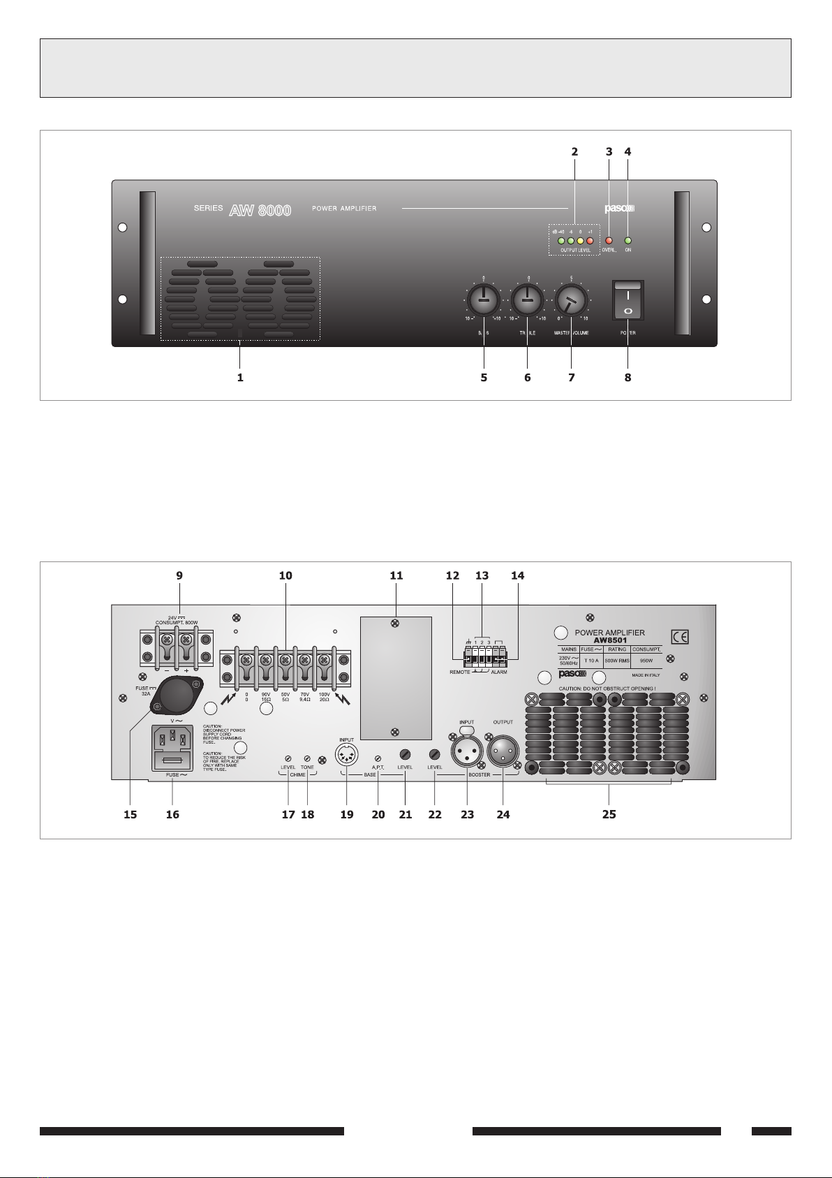
2.2 ALIMENTAZIONE E MESSA A TERRA
Lapparecchio è predisposto per il funzionamento con tensione di rete
a 230 V ± 10% 50/60 Hz (117 V ± 10% 50/60 Hz per la versione
AW8501/117). E prevista, in alternativa, la possibilità di alimentare
lapparecchio con una tensione continua esterna di +24V. Tipicamente
questa tensione, che deve essere applicata, rispettando le polarità,
ai relativi terminali della morsettiera [9], proviene da accumulatori
mantenuti sotto carica in tampone ed entra in funzione soltanto in
caso di emergenza; è necessario, in questo caso, prevedere luso di
un relè esterno che connetta le batterie allapparecchio solo quando
viene a mancare lalimentazione di rete.
In accordo con le normative di sicurezza, linterruttore di accensione
[8] agisce solo sulla tensione di rete.
Lapparecchio é corredato di cavo di alimentazione con filo di terra ed
il relativo terminale sulla spina di rete non deve essere rimosso in alcun
caso. Assicurarsi che la presa di corrente sia dotata di collegamento di
terra a norma di legge.
2.2 POWER SUPPLY AND EARTH ING
The apparatus is designed for operation with a mains power supply of
230 V ± 10% 50/60 Hz (117 V ± 10% 50/60 Hz for the AW8501/117
version). As an alternative, it is possible to supply the apparatus with
an external continuous voltage of +24V. Typically, this voltage, which
must be applied observing the polarities at the relevant terminals of the
terminal strip [9], is provided by accumulators under floating charge,
and is only applied in case of an emergency. In this case, it is necessary
to arrange for use of an external relay which only connects the batteries
to the apparatus in the event of failure of the mains power supply.
In accordance with the safety standards, the power supply switch [8]
only switches the mains voltage.
The apparatus is supplied with a power cord equipped with earthing
wire and the relevant terminal on the mains plug should never be removed
for any reason whatsoever. Make sure that the power outlet is equipped
with an earthing connection in accordance with legal requirements.
2.3 NOTE DI SICUREZZA
Ogni intervento allinterno dellapparecchio, quale la selezione di alcuni
modi duso, lapplicazione di accessori o la sostituzione di fusibili, deve
essere effettuato solo da personale specializzato: la rimozione del
coperchio rende accessibili parti con rischio di scosse elettriche.
Prima di rimuovere il coperchio accertarsi sempre che il cavo di rete sia
staccato.
Nel caso di accidentale caduta di liquidi sullapparecchio, staccare
immediatamente la spina di rete ed interpellare il centro di assistenza
PASO più vicino. La connessione di massa telaio [12] consente di collegare
altre apparecchiature per la sola funzione di schermatura dei segnali a
basso livello: questa presa non deve essere utilizzata per il collegamento
di sicurezza del telaio alla terra.
2.3 SAFETY NOTES
Any activities inside the apparatus, such as selecting some of the
operating modes, the installation of accessories or the replacement of
fuses, must be carried out by specialized personnel only: when the
cover is removed, parts liable to cause electric shocks are exposed.
Before removing the cover, always make sure that the power cord has
been disconnected.
In the event that liquid is accidentally spilt onto the apparatus, disconnect
the mains plug immediately and contact the nearest PASO Service
Centre. The chassis earth connection [12] may be used to connect
other equipment only for the purpose of shielding the low signals: this
socket may not be used to connect the chassis to earth for safety
purposes.
11-544.p65 08/02/02, 10.474

SERIE AW8000 5
CONNECTIONS3CONNESSIONI
3.1 CRITERI GENERALI
Per un corretto funzionamento dell'apparecchio è opportuno osservare
alcuni criteri di massima nell'esecuzione dei collegamenti:
- evitare il posizionamento di cavi e di microfoni sul mobile
dell'apparecchio;
- evitare di stendere le linee di segnale parallele a quelle di rete;
- osservare una distanza minima di 30/40 cm;
- posizionare le linee di ingresso e le linee di uscita distanti tra loro;
- posizionare i microfoni al di fuori dell'angolo di radiazione dei diffusori
sonori per evitare il fenomeno di reazione acustica (effetto Larsen).
ATTENZIONE
L'installazione di accessori all'interno dell'apparecchio e la selezione di
alcuni controlli di tipo impiantistico, richiede la rimozione del coperchio.
Questo tipo di operazione deve essere effettuata solo da personale
specializzato: la rimozione del coperchio rende accessibili parti con rischio
di scosse elettriche.
Prima di rimuovere il coperchio accertarsi sempre che il cavo di rete sia
staccato.
Fig. 3.2.2
1= Schermo
2= Segnale (lato caldo)
3 = Segnale (lato freddo)
1= Shield
2= Signal (warm side)
3 = Signal (cold side)
3.1 GENERAL FEATURES
For proper unit operation, use the following instructions when making
the connections:
- Do not place cables or microphones on the unit cabinet;
- Do not lay signal lines parallel to power lines;
- Ensure a minimum distance of 30/40 cm between them;
- Keep input lines and the output lines far apart;
- Keep the microphones outside the operating span of the speakers to
avoid acoustic feedback (Larsen effect).
WARNING
To install options within the unit and to select some system controls, the
cover must be removed.
This operation should only be performed by qualified service personnel
as it poses the risk of electric shock.
Before removing the cover, ensure that mains cable is disconnected.
3.2 LINE INPUT
The female XLR socket BOOSTER INPUT [23] on the rear panel of the
equipment provides the line input for the power unit. The input sensitivity
is adjusted by means of the relevant LEVEL control [22].
The male XLR plug BOOSTER OUTPUT provides the same signal as on
the INPUT socket, making it easy to connect several units to one
another in cascade fashion. The input is electronically balanced, and it
is in any case possible to insulate the input of the amplifier galvanically
by means of the optional TM92 card, which is equipped with a line
repeating coil. To do this, it is necessary to remove the short-circuiting
j
umpers from connector CN202, situated on the input circuit (see Figure
3.2.1) and to insert card TM92. Figure 3.2.2 shows the connections,
seen from outside.
Fig. 3.2.1
3.2 INGRESSO DI LINEA
Sul pannello posteriore dellapparecchio è disponibile lingresso di linea
dellunità di potenza tramite la presa XLR femmina BOOSTER INPUT [23].
La sensibilità dingresso è regolata dal relativo controllo LEVEL [22].
La spina XLR maschio BOOSTER OUTPUT fornisce lo stesso segnale
presente alla presa INPUT, per un facile collegamento in cascata tra più
unità di potenza. Lingresso è bilanciato elettronicamente, ed è comunque
possibile isolare galvanicamente lingresso dellamplificatore tramite la
scheda opzionale TM92, dotata di traslatore di linea.
Allo scopo, occorre rimuovere dal connettore CN202, posto sul circuito
ingressi (vedi fig. 3.2.1) i ponticelli circuitanti ed inserire la scheda TM92.
La figura 3.2.2 riporta le connessioni, viste dallesterno.
11-544.p65 08/02/02, 10.475

SERIE AW8000
6
CONNECTIONS
3CONNESSIONI
3.3 INGRESSO BASE AMPLIFICATA
La presa DIN pentapolare BASE INPUT [19] permette il collegamento
dell'amplificatore alle basi preamplificate PASO Serie B600, fino ad un
massimo di sei.
In figura 3.3.1 si evidenziano i collegamenti della presa, vista dall'esterno,
con i relativi segnali ed alimentazioni.
3.3 AMPLIFIED STAND INPUT
The BASE INPUT five-pin DIN socket [19] is designed to connect the
amplifier to up to six preamplified PASO B600 Series stands.
Figure 3.3.1 shows socket connections as seen from the outside, with
pertaining signals and power supplies.
Fig. 3.3.1
1= Precedenza
2= Schermo e ritorno del segnale dingresso
3= Segnale dingresso
4= Alimentazione +12Vcc stabilizzati
5= Massa alimentazione
Il livello del segnale inviato alla presa BASE INPUT può essere regolato
dal potenziometro LEVEL [21].
Questa presa è utilizzabile anche per altri impieghi:
ingresso di bassa frequenza aggiuntivo, con sensibilità 170 mV,
soggetto ad attenuazione di precedenza ed eventualmente utilizzabile
per la generazione di precedenza automatica.
alimentazione di dispositivo esterno tramite la tensione stabilizzata
12 Vcc; l'erogazione massima di corrente è pari a 200 mA medi con
picchi massimi di 1 A.
The level of the signal sent to the BASE INPUT socket may be adjusted
through the LEVEL potentiometer [21].
This socket may also be used in the following ways:
Additional low-frequency input, with a sensitivity of 170 mV, subject
to attenuation due to precedence and which can be used, if required,
to generate automatic precedence.
power supply of an external device by stabilized 12 Vdc voltage;
maximum current output is 200 mA (average) with maximum peaks
of 1 A.
Precedenza base amplificata
Premendo il tasto di chiamata su una base Serie B600 collegata al
relativo ingresso dellamplificatore [19], si attiva il segnale di precedenza
che attenua automaticamente lingresso di linea.
E così possibile inviare un messaggio dalla base microfonica senza
sovrapposizione di segnale musicale.
Precedenza automatica
Un circuito elettronico rivela la presenza di segnale all'ingresso BASE
INPUT [19] e attiva automaticamente la precedenza per permettere la
diffusione di un messaggio da questo ingresso.
Il livello di segnale necessario all'attivazione della precedenza automatica
può essere regolato tramite il controllo A.P.T. (Automatic Precedence
Threshold), accessibile dal pannello posteriore.
La regolazione è necessaria al fine di evitare l'attivazione della precedenza
automatica per effetto di eventuali rumori di fondo raccolti dal microfono.
Amplified stand precedence
When the call pushbutton on a B600 Series base connected to the
pertaining amplifier input [19] is pressed, this triggers the precedence
signal which automatically attenuated the line inlet. In this way, a message
can be sent by the microphone base without any music signal overlay.
Automatic precedence
An electronic circuit detects the presence of the signal on the BASE
INPUT input [19] and automatically controls the precedence for the
emission of a message from this input.
The signal level required to activate the automatic precedence may be
adjusted through the A.P.T. (Automatic Precedence Threshold) control,
which can be accessed from the rear panel.
This adjustment is required to avoid the activation of the automatic
precedence due to background noise picked up by the microphone.
1= Precedence
2= Shield and input signal return
3= Input signal
4= Stabilized +12Vcc power supply
5= Power ground
11-544.p65 08/02/02, 10.476

SERIE AW8000 7
CONNECTIONS
3CONNESSIONI
3.4 USCITE DI POTENZA
Le uscite di potenza per i diffusori sono disponibili sulla morsettiera [10].
È possibile realizzare un impianto di diffusione sonora utilizzando sia
diffusori a bassa impedenza, sia diffusori dotati di traslatore di linea.
In entrambi i casi il carico complessivo non deve essere tale da
sovraccaricare lamplificatore: non applicare cioè diffusori o gruppi di
diffusori con impedenza più bassa di quella nominale della presa alla quale
sono collegati. Si raccomanda inoltre di porre particolare attenzione al
calcolo delle impedenze nel caso si debbano realizzare impianti di diffusione
misti (a bassa impedenza e a tensione costante).
In tabella 3.4.1 sono riportati i valori nominali di tensione ed impedenza
per le diverse uscite.
3.4 POWER OUTPUTS
The power outputs for the loudspeakers are available on the terminal
strip [10]. It is possible to set up a sound-broadcasting system
using either low-impedance loudspeakers or loudspeakers equipped with
a line transformer. In both cases the overall load must not be such as to
overload the amplifier. This means that you must not apply loudspeakers
or groups of loudspeakers with an impedance lower than the rated
impedance of the socket to which they are connected. It is also necessary
to pay particular attention to calculating the impedance values if mixed
broadcasting systems (low impedance and constant voltage) are to be
set up. Table 3.4.1 shows voltage and impedance rated values for the
various outputs.
Tabella 3.4.1
Uscita
90 V
50 V
70 V
100 V
AW8501
16 Ω
5 Ω
9,4 Ω
20 Ω
Table 3.4.1
Output
90 V
50 V
70 V
100 V
AW8501
16 Ω
5 Ω
9,4 Ω
20 Ω
3.4.1 Sistemi a bassa impedenza
In applicazioni che richiedono luso di pochi altoparlanti, la linea di
collegamento può essere connessa tra il terminale comune 0 e la presa
16 ΩΩ
ΩΩ
Ω della morsettiera [10].
Il collegamento degli altoparlanti, di tipo serie o parallelo o misto, deve
fornire unimpedenza calcolata pari o superiore a 16Ω.
Nelle figure 3.4.1/3.4.2 sono riportati degli esempi di collegamento.
Calcolo dellimpedenza nei collegamenti in serie
Nel caso di diffusori collegati in serie tra loro, limpedenza totale è la
somma delle singole impedenze:
impedenza totale = Z1 + Z2 + Z3 +....
Calcolo dellimpedenza nei collegamenti in parallelo
Nel caso di diffusori collegati in parallelo tra loro, limpedenza totale può
essere determinata mediante la seguente formula:
1
1
Z1
1
Z2
+1
Z3
+ + ......
impedenza totale =
Calculating the impedance value in series connections
In the case of loudspeakers connected to one another in series, the total
impedance is the sum of the single impedance values:
Total impedance = Z1 + Z2 + Z3 +....
Calculating the impedance value in parallel connection
In the event of loudspeakers connected in parallel to one another the
total impedance can be calculated by means of the following formula:
1
1
Z1
1
Z2
+1
Z3
+ + ......
Total impedance =
3.4.1 Low-impedance systems
In applications that require the use only of a few loudspeakers, the
connecting line may be connected between the common terminal 0 and
the 16 ΩΩ
ΩΩ
Ω socket of the terminal strip [10].
The loudspeaker connection, whether of the serial or parallel type or
mixed, should provide an impedance calculated to be equal to or higher
than 16 Ω. Some example of connection is shown in Figures 3.4.1/3.4.2.
Fig. 3.4.1 Fig. 3.4.2
11-544.p65 08/02/02, 10.477

SERIE AW8000
8
CONNECTIONS
3CONNESSIONI
3.4.2 Sistemi a tensione costante
Nel caso di impianti con un gran numero di diffusori e/o con distanze tra
amplificatori ed altoparlanti molto elevate é preferibile utilizzare un sistema
di distribuzione a tensione costante (definito anche ad alta impedenza).
In questo tipo di impianto, i diffusori, provvisti di trasformatori di
adattamento di impedenza, sono tutti collegati in derivazione alla linea
(vedi es. di Fig. 3.4.3); questo particolare rende di facile realizzazione
limpianto e, nel caso in cui un altoparlante dovesse per qualche motivo
scollegarsi dalla linea, il resto dellimpianto proseguirebbe nel suo regolare
funzionamento. Le tensioni costanti disponibili in uscita dallamplificatore
sono 90, 50, 70 e 100 V.
Fig. 3.4.3
3.4.2 Constant voltage systems
When a large number of speakers is used and/or the speakers are
placed far from the amplifiers, constant voltage distribution system
should be used (also known as high-impedance systems).
In this type of system, the speakers are fitted with impedance
adaptation transformers and all of them have shunt line connections
(see example of Fig. 3.4.3).
This simplifies the layout of the system and if, for any reason, a
loudspeaker is disconnected from the line, the rest of the system will
continue to work properly. The constant voltages output from the
amplifier are 90, 50, 70 and 100 V.
Calcolo del numero di diffusori (tramite le potenze)
Si supponga di avere definito sia l'amplificatore (cioè la sua potenza di
uscita) che il tipo di diffusore con relativa potenza assorbita.
In questo caso il massimo numero di diffusori collegabile sulla linea è
determinato dalla seguente formula:
Esempio: si utilizzino un amplificatore AW8501 con plafoniere modello
Paso C52/10-T. L'amplificatore è in grado di erogare una potenza pari
a 500 W, mentre un diffusore assorbe una potenza di 10 W.
Per sapere quanti diffusori sono collegabili alla linea di uscita si calcola:
Determining the number of speakers (through power values)
If both the amplifier (i.e. its output power) and the type of speaker
with its power consumption have been established, the maximum number
of speakers which may be connected to the line may be determined as
follows:
Example: in a system including a AW8501 amplifier with ceiling
speakers type Paso C52/10-T is used, the amplifier can supply 500 W
power whereas the speaker has a power consumption of 10 W.
The number of speakers which may be connected to the output line is:
500 W
10 W
numero diffusori = = 50
numero diffusori =potenza amplificatore
potenza diffusore number of speakers =amplifier power
speaker power
500 W
10 W
number of speakers == 50
Calcolo del numero di diffusori (tramite le impedenze)
Se il dato disponibile è l'impedenza del diffusore, il numero massimo di
diffusori collegabili ad una linea è:
dove l'impedenza nominale dell'amplificatore
è
ricavabile dalla
tabella 3.4.1.
Esempio: si utilizzino un amplificatore AW8501 con diffusori tipo
Paso C48-T, che presentano una impedenza pari a 833 ohm.
Dalla tabella 3.4.1 si trova che l'impedenza nominale di carico della linea
a 100 V è pari a 20 ohm.
Quindi:
Determining the number of speakers (through impedance)
If the impedance of the speaker is known, the maximum number o
f
speakers which may be connected to the line is:
where the amplifier rated impedance may be determined referring to
Table 3.4.1.
Example: If a AW8501 amplifier is used with speakers type Paso
C48-T having a 833 ohm impedance, the rated load impedance of the
line at 100 V may be determined from Table 3.4.1 as being equal to
20 ohm.
Thus:
number of speakers =speaker impedance
amplifier impedance
833 Ω
20 Ω
number of speakers == 41
numero diffusori =impedenza diffusore
impedenza amplificatore
833 Ω
20 Ω
numero diffusori = = 41
11-544.p65 08/02/02, 10.478

SERIE AW8000 9
CONNECTIONS
3CONNESSIONI
3.5 FILTRO SELEZIONE VOCE
L'inserimento di questo filtro può contribuire al miglioramento
dell'intelligibilità della parola in ambienti riverberanti o particolarmente
affollati; esaltando le frequenze del parlato, si concentra tutta la potenza
dell'amplificatore in questa banda, ottenendo quindi una più elevata
dinamica in uscita ed una maggiore chiarezza. Si consiglia, in particolare,
di inserire questo filtro in impianti con diffusori a tromba, in quanto un
eccessivo livello di frequenze basse potrebbe danneggiare la membrana
del diffusore. Per inserire il filtro é necessario modificare la posizione del
ponticello, posto sul circuito di controllo e pilotaggio dell'apparecchio,
come indicato in figura 3.5.1.
3.5 VOICE SELECTION FILTER
The use of this filter improves the voice comprehension in highly
reverberating or heavy-crowded rooms.
By emphasizing voice frequencies, the whole amplifier power is
concentrated in this band, thus offering higher output dynamics and
better clarity.
This filter should be installed in particular in systems with horn speakers,
as too many low frequencies could damage the speaker diaphgram.
To install the filter, the position of the jumper on the control and driving
circuit of the equipment must be changed as shown in Figure 3.5.1.
Fig. 3.5.1
Posizione A= Filtro inserito
Posizione B= Filtro disinserito Position A= Filter ON
Position B= Filter OFF
3.6 MODULI ACCESSORI
Per inserire i moduli accessori nell'amplificatore è necessario rimuovere
il coperchio dell'apparecchio. Rammentiamo che questa operazione deve
essere affidata a personale specializzato e, comunque, si richiama quanto
riportato al paragrafo 1.3.
3.6 OPTIONAL MODULES
To install optional modules in the amplifier, the cover of the unit must be
removed.
As mentioned above, this operation should only be performed by qualified
personnel according to section 1.3.
Scheda din-don
Sul circuito ingresso linea é predisposto un connettore a 6 piedini,
denominato CN201 (vedi Fig. 3.6.1), per linserzione della scheda AC25
per la generazione del segnale di preavviso (DIN-DON).
Tale segnale é attivato dalla chiusura dei contatti dallinserzione di una
base amplificata collegata allingresso BASE INPUT [19].
Le regolazioni del volume [17] e della tonalita [18] del DIN-DON sono
accessibili dal pannello posteriore tramite un piccolo cacciavite a taglio.
CHIME Module
A 6-pin connector named CN201 (see Figure 3.6.1) is available on the
input circuit board, which can house the plug-in AC25 board for the
generation of the pre-warning signal (CHIME).
This signal is activated when an amplified stand connected to the BASE
INPUT [19] is activated.
The chime volume [17] and tone controls [18] may be accessed from
the rear panel by means of a small screwdriver.
Fig. 3.6.1
11-544.p65 08/02/02, 10.479

SERIE AW8000
10
Scheda allarme
Sul circuito controllo e pilotaggio (vedi Fig. 3.6.2) è predisposto un
connettore a 5 piedini, denominato CN301, per linserzione della scheda
di allarme AC21. La piattina di collegamento della scheda deve essere
inserita nel connettore a 3 piedini CN11, posto sul circuito ingressi
(Fig. 3.2.1). Per le regolazioni del segnale di allarme, riferirsi al foglio di
istruzione dellaccessorio. Lattivazione del segnale avviene mettendo
in cortocircuito i due contatti ALARM della morsettiera [14] posta sul
pannello posteriore dellapparecchio; la chiusura deve essere realizzata
tramite un contatto a secco (tipo pulsante, interruttore o scambio di
relais). In figura 3.6.3 si riporta un esempio di realizzazione.
Alarm board
A 5-pin connector named CN301 is available on the control and driving
circuit (see Figure 3.6.2) which can house the plug-in AC21 alarm board.
The board connection strap must be plugged into the 3-pin CN11
connector (see Figure 3.2.1). For the alarm signal adjustment, see
instructions supplied with the option.
The signal is activated when the two ALARM contacts of the terminal
board [14] on the rear panel of the unit are short circuited; the circuit
must be closed by means of a dry contact (such as a pushbutton, a
switch or a relay switching operation). An example of application is
shown on Figure 3.6.3.
Fig. 3.6.3
Sistema per allarme antincendio
Fire alarm system
Sensori di fumo / Smoke sensors
Centralina rilev. di fuoco
Fire detection unit
Fig. 3.6.2
CONNECTIONS
3CONNESSIONI
Scheda di controllo volume a distanza
Sul circuito di controllo e pilotaggio é predisposto un connettore a 5
piedini, denominato CN302 (vedi Fig. 3.6.2), per linserzione della
scheda per il controllo di volume a distanza AC20. La piattina di
collegamento della scheda deve essere inserita nel connettore a 3 piedini
CN10, posto sul circuito ingressi (vedi Fig. 3.2.1). Il circuito possiede un
range di regolazione maggiore di 40 dB in 16 passi.
Di seguito si descrivono due tipiche applicazioni:
Remote volume control board
A 5-pin connector named CN302 (see Figure 3.6.2) is available on the
control and driving circuit which can house the AC20 volume remote
control plug-in board. The board connection strap must be plugged into
the CN10 3-pin connector, situated on the input circuit board (see
Figure 3.2.1). This circuit has an adjustment range of 40 dB in 16 steps.
Here follow the descriptions of two typical applications:
1) Regolazione continua di volume
La regolazione può avvenire tramite un potenziometro
da 50 kΩlineare connesso come in figura 3.6.4.
Fig. 3.6.4
1) Continuous volume adjustment
The adjustment may be performed through a 50 kΩ
linear potentiometer connected as shown on Figure
3.6.4.
11-544.p65 08/02/02, 10.4710

SERIE AW8000 11
CONNECTIONS
3CONNESSIONI
La correzione logaritmica del volume é già realizzata dallattenuatore
interno allamplificatore. Per una efficace pre-regolazione dei livelli, si
consiglia di porre a centro corsa il potenziometro e selezionare il livello
di uscita desiderato con il controllo pricipale MASTER VOLUME [7].
In questo modo, il potenziometro del controllo a distanza ha una capacità
di regolazione di 20 dB in aumento od in diminuzione rispetto al livello
prefissato con il controllo MASTER VOLUME.
The volume logarithmic adjustment is already performed by the
attenuator built into the amplifier. For an effective level pre-adjustment,
the VR should be set to the mid-range and the output level should be
selected as required by means of the MASTER VOLUME control [7].
In this way, the remote control VR has an adjustment capacity of 20 dB
above or below the level preset with the MASTER VOLUME control.
ESEMPIO:
R1 = 6K8
R2 = 27 K
Attenuazione con contatto A chiuso:
40 x 27 K (27 K-6K8) = 32 dB
Scegliere R1 o R2 in modo che
30 kΩ≤R1 + R2 ≤50 KΩ
Fig. 3.6.5
EXAMPLE:
R1 = 6K8
R2 = 27 K
damping with closed A contact:
40 x 27 K (27 K-6K8) = 32 dB
Choose R1 or R2 in order that
30 kΩ≤R1 + R2 ≤50 KΩ
Controllo del livello di uscita su due livelli
La regolazione, in questo caso, avviene tramite un partitore resistivo
inserito da un contatto a secco come in configurazione di figura 3.6.5.
Quando il contatto Aè aperto, l'attenuazione è nulla.
Quando il contatto A è chiuso, il segnale è attenuato di una quantità
data dalla formula:
attenuazione (dB) = 40 x R2/(R1+R2)
Output two-level control
In this case, adjustment is performed by means of a resistive divider
which is triggered by a dry contact as shown on Figure 3.6.5.
When contact Ais opened, damping is zero.
When contact Ais closed, the signal is attenuated by a value resulting
from the following:
attenuation (dB) = 40 x R2/(R1+R2)
Questo controllo trova la sua applicazione in impianti con diffusione in
luoghi aperti, per ridurre il livello sonoro nelle ore serali e notturne e
l'attuatore di inserzione è il contatto di un timer.
This control is switchable for outdoor sound systems in order to reduce
the sound level in the evening and at night; the triggering actuator is a
timer contact.
3.7 MODULI
Per estendere le prestazioni dellapparecchio, è stata prevista una serie
di moduli da inserire nellapposito vano [11].
Lapparecchio viene fornito con un pannellino di chiusura standard.
Per inserire i moduli accessori nellamplificatore, operare come segue:
1. togliere le due viti (A) che fissano il pannellino di chiusura al posteriore
dellamplificatore (figura 3.7.1).
2. Estrarre il pannellino e sfilare dai distanziali in plastica posti sul lato
interno il circuito (B).
3. Posizionare il circuito (B) come illustrato in figura 3.7.2.
NOTA: nel caso si dovesse utilizzare il modulo AC8051-B, collegare la
piattina al connettore (C).
4. Fissare il modulo nel connettore (D) e, sfruttando gli scarichi presenti
sul margine dellapertura, inserire il modulo così collegato allinterno
dellamplificatore (fig. 3.7.3).
5. Fissare il pannello del modulo al posteriore dellamplificatore riutilizzando
le viti precedentemente rimosse.
3.7 MODULES
To extend the features of the equipment, a range of modules to be
inserted into the compartment provided for this purpose has been
envisaged [11]. The equipment is supplied with a standard panel for
closing the compartment.
To plug the accessory modules into the amplifier, proceed as follows:
1. Remove the two screws (A) that fix the panel covering the
compartment to the rear of the amplifier (Figure 3.7.1).
2. Remove the panel and pull the circuit out of the plastic spacers situated
on the inside (B).
3. Position the circuit (B) as illustrated in Figure 3.7.2.
NOTE: If you wish to use module AC8051-B, connect the flat twin
cable to connector (C).
4. Plug the module into the connector (D) and, exploiting the recesses
present on the edge of the opening, insert the plugged-in module
inside the amplifier (Figure 3.7.3).
5. Secure the panel of the module to the rear of the amplifier using the
screws that had previously been removed.
Fig. 3.7.1 Fig. 3.7.2 Fig. 3.7.3
11-544.p65 08/02/02, 10.4711

SERIE AW8000
12
4.1 ACCENSIONE
Prima di mettere in funzione l'apparecchio accertarsi di avere realizzato
tutte le connessioni necessarie al completamento dell'impianto.
Portare l'interruttore di rete [8] in posizione ON.
La spia luminosa ON [4] confermerà l'accensione dell'apparecchio.
Se necessario, regolare il livello di ascolto tramite il controllo MASTER
VOLUME [7] e ritoccare i livelli delle sorgenti sonore per una corretta
equalizzazione dei segnali tramite i controlli del livello [5] e [6].
4.1 POWER ON
Before switching the unit on, check that all the connections have been
correctly made.
Set the mains switch [8] to the ON position.
The ON [4] LED lights up, when the unit is switched on.
If necessary, adjust the listening level by means of the MASTER VOLUME
control [7] and adjust the levels of the sound sources for correct
equalisation of the signals by means of the level controls [5] and [6].
OPERATION
4USO DELLAPPARECCHIO
4.2 VENTILAZIONE FORZATA
L AW8501 (AW8501/117) dispone di due ventole per la ventilazione
forzata degli stadi finali di potenza. Queste ventole, asservite da un
proprio circuito di alimentazione e controllo, si attivano automaticamente
al raggiungimento di una determinata temperatura dei dissipatori di calore
e si arrestano quando la temperatura ritorna a livelli normali. In pratica,
in condizioni duso tipiche per amplificatori di questa caratura, quali la
diffusione di musica di sottofondo intervallata da annunci vocali a piena
potenza, ed in condizioni climatiche normali, la ventilazione forzata non si
rende necessaria e non viene quindi attivata; ciò comporta una notevole
riduzione dellusura meccanica delle parti in movimento, la riduzione
dellaccumulo di polvere introdotta nellapparecchio dalle ventole e, non
ultima, la riduzione del rumore ambientale causato dallelevato numero di
ventole in rotazione nel caso di impianti con uno o più armadi contenenti
un gran numero di booster.
4.2 FORCED VENTILATION
The AW8501 (AW8501/117) has two fans for forced ventilation of the
end power stages. These fans, with their own power supply and control
circuit, are activated automatically whenever the dissipators reach a
given heat temperature, and they switch off when the temperature has
returned to a normal level. In practice, in typical operating conditions for
amplifiers with this rating, such as the broadcasting of background music
interrupted by voice announcements at the full output power, and in
normal climatic conditions, forced ventilation is not necessary and will
therefore not be activated. This means a considerable reduction in the
rate of mechanical wear of the moving parts, a reduction in the quantity
of dust accumulating inside the equipment after entering through the
fans and, last but not least, reduction of the backgroud noise level caused
by the high number of fans that are turning in systems with one or more
cabinets containing a large number of boosters.
4.3 CONTROLLO DI VOLUME PRINCIPALE
Il controllo di volume principale MASTER VOLUME [7] regola il livello
complessivo del segnale di uscita. Per ottenere in uscita un segnale
privo di distorsione, si raccomanda di controllare che sullindicatore del
livello di uscita OUTPUT LEVEL [2] non si accenda la spia di colore
rosso (+1 dB) o , comunque, che ciò avvenga saltuariamente; in caso
contrario, è necessario diminuire il livello di uscita agendo sul comando
MASTER VOLUME [7]. La potenza di uscita nominale è segnalata
dallaccensione della spia luminosa gialla (0 dB).
4.3 MASTER VOLUME CONTROL
The MASTER VOLUME control [7] adjusts the output signal.
To obtain a distorsion-free output signal, check that the red LED
indicator (+1 dB) on the OUTPUT LEVEL indicator [2] is not on, or at
any rate that it does not light up frequently; otherwise, the output
level should be reduced by the MASTER VOLUME control [7].
The rated output power is reached when the yellow LED indicator
(0 dB) lights up.
4.4 CORREZIONE ACUSTICA
I controlli BASS [5] e TREBLE [6] modificano la tonalità del segnale di
uscita derivato dalla miscelazione dei vari segnali di ingresso.
4.4 ACOUSTIC ADJUSTMENT
The BASS [5] and TREBLE [6] controls adjust the output signal tone
generated by mixing the different input signals.
Controllo toni bassi (BASS)
Il controllo BASS [5] regola le prestazioni dellamplificatore alle basse
frequenze. La posizione di centro, indicata dallo 0, fornisce una risposta
lineare; per avere una esaltazione delle frequenze basse ruotare la
manopola in senso orario; per ottenere una attenuazione ruotare la
manopola in senso antiorario.
Usare il comando BASS per minimizzare la retroazione acustica diffusore-
microfono (effetto Larsen), posizionandolo nellintervallo di attenuazione.
Utilizzando diffusori a tromba é opportuno, tramite il comando BASS,
attenuare le frequenze basse; un eccessivo livello delle basse frequenze
potrebbe danneggiare la membrana del diffusore.
Bass control (BASS)
The BASS control [5] adjusts the amplifier performance at low
frequencies. The center position 0 provides a linear response.
To emphasize low frequencies, turn the knob clockwise; to attenuate
them, turn the knob anticlockwise.
Use the BASS control to reduce the microphone-speaker acoustic
feedback (Larsen effect) by positioning it in the attenuation range.
When horn-type speakers are used, low frequencies should be
attenuated by means of the BASS control. An excessive low frequency
level could damage the speaker membrane.
Controllo toni acuti (TREBLE)
Il controllo TREBLE [6] regola le prestazioni acustiche dell'amplificatore
alle alte frequenze. La posizione di centro, indicata dallo 0, fornisce una
risposta di tipo lineare; per avere una esaltazione delle frequenze alte
ruotare la monopola in senso orario. Lattenuazione dei toni acuti è utlie
per minimizzare un eccessivo livello di fruscio o per rendere più dolci suoni
particolarmente sibilanti.
Treble control (TREBLE)
The TREBLE [6] control adjusts the amplifier performance at high
frequencies. The center position 0 provides a linear response.
To emphasize high frequencies, turn the knob clockwise; to attenuate
them, turn the knob anticlockwise.
Attenuation of the treble tones is useful for minimising and excessive
level of rustling or in order soften hissing sounds.
11-544.p65 08/02/02, 10.4712

SERIE AW8000 13
SERVICE NOTES
5NOTE DI SERVIZIO
5.2 REGOLAZIONE DELLAPPARECCHIO
Taratura della corrente a riposo dello stadio finale (da effettuare con
apparecchio freddo e con volume principale al minimo):
1. Regolare P101 fino a misurare una tensione di 3 mV ai capi di R110.
2. Regolare P151 fino a misurare una tensione di 3 mV ai capi di R160.
Taratura di fondo-scala dell'indicatore della potenza di uscita:
1. Portare l'amplificatore a potenza nominale su carico nominale con
segnale sinusoidale a 1 kHz.
2. Regolare P801 per avere l'accensione del led rosso.
3. Diminuire lentamente P801 fino allo spegnimento del led rosso.
5.2 EQUIPMENT ADJUSTMENTS
Calibration of the idle current on the end stage (to be performed when
the equipment is cold and the main volume is to the minimum):
1. Adjust P101 until a 3 mV voltage is measured at the R110 ends.
2. Adjust P151 until a 3 mV voltage is measured at the R160 ends.
Full-scale calibration of the output power indicator:
1. Set the amplifier to the rated power at rated load and 1 kHz sinusoidal
signal.
2. Adjust P801 until the red LED lights up.
3. Gradually reduce P801 until the red LED extinguishes.
5.1 CONDIZIONI DI SOVRACCARICO E PROTEZIONE
Applicare un valore di impedenza di carico inferiore a quella nominale
significa richiedere all'apparecchio una potenza superiore a quella
erogabile con continuità. Questo potrebbe portare al danneggiamento
degli stadi finali di potenza e del trasformatore di uscita.
Per non incorrere in questi inconvenienti gli amplificatori della serie
AW8000 sono dotati di circuito di protezione contro i sovraccarichi con
ripristino automatico.
Il circuito di protezione interverrà immediatamente sull'amplificatore
qualora si verificasse uno dei seguenti casi:
- cortocircuito su una delle uscite per altoparlanti;
- impedenza di carico inferiore al 70% del valore nominale;
- potenza richiesta dal sistema di diffusori, collegati sulle linee a tensione
costante, superiore a quella erogabile dall'amplificatore.
La condizione di sovraccarico è segnalata dall'accensione, intermittente
della spia luminosa OVERL. [3] posta sul pannello frontale
dall'apparecchio. L'apparecchio riprenderà il regolare funzionamento non
appena si sarà provveduto a rimuovere la causa del sovraccarico.
Per i valori di impedenza e di tensione nominali per le diverse uscite e
per il corretto dimensionamento di un impianto si veda il par.3.4.
5.1 OVERLOAD AND PROTECTION CONDITIONS
When a load impedance value lower than the rated one is applied, the
unit will have to supply a greater power level than it can deliver
continuously.
This could damage the end power stages and the output transformer.
To avoid such problems, the AW8000 series amplifiers are provided
with an overload protection circuit with automatic reset.
The protection circuit will be immediately operated in the following cases:
- short circuit at one of the loudspeaker outputs;
- load impedance less than 70% of the rated value;
- a demand for power from loudspeakers connected to constant voltage
lines which is greater than the maximum power the amplifier can
deliver.
The overload condition is signalled by the intermittent lighting of the
OVERL. LED indicator [3] on the unit front panel.
The unit will resume normal operation as soon as the cause of the
overload has been removed.
The various rated impedance and voltage values for different outputs
as well as for a proper system set-up can be found in section 3.4.
11-544.p65 08/02/02, 10.4713

SERIE AW8000
14
TECHNICAL SPECIFICATIONS
6CARATTERISTICHE TECNICHE
elanimonaticsuidaznetoP W005 rewoplanimoN
etnatsocenoisnetaaticsU V09,05,07,001
61,5,4.9,02(
Ω
)stuptuoegatlovtnatsnoC
elanimonaznetopallaenoisrotsiD %1< rewopdetartanoisrotsiD
issabinotenoizerrocotnevretnI )zH001(Bd01± lortnocsenotssaB
itucainotenoizerrocotnevretnI )zHk01(Bd01± lortnocsenotelberT
TUPNIRETSOOBRETSOOBOSSERGNI )decnalab-otaicnalib(
aznedepmi/àtilibisneS k001Vm084
Ω
ecnadepmi/ytivitisneS
obrutsid/elangesotroppaR Bd08> oitarN/S
azneuqerfniatsopsiR )Bd3-/0(zH00002÷05 esnopseRycneuqerF
aznedecerpenoizaunettA Bd04> noitaunettaecnedecerP
TUPNIDNATSDEIFILPMAATACIFILPMAESABOSSERGNI
aznedepmi/àtilibisneS k01Vm071
Ω
ecnadepmi/ytivitisneS
obrutsid/elangesotroppaR Bd08> oitarN/S
azneuqerfniatsopsiR )Bd3-/0(zH00002÷081 esnopseRycneuqerF
.xamotnemibrossA Am002 noitprosbatnerruc.xaM
SNOITIDNOCGNITAREPOOTNEMANOIZNUFIDINOIZIDNOC
eteradenoizatnemilA %01±V032 zH06/05 )1058WA(
%01±V711 zH06/05 )711/1058WA( ylppusrewopsniaM
aznetopidomusnoC )eteradenoizatnemila( AV0511/W059 noitpmusnocrewoP )ylppusrewopsniam(
.c.cnianretseenoizatnemilA V42 ylppusrewopCDlanretxE
etnerrocidomusnoC )aunitnocetnerrocnianretseenoizatnemila( )XAM(A52 noitpmusnoctnerruC )ylppusrewopCD.TXE(
)PxAxL(inoisnemiD mm024x331x284 )DxHxW(snoisnemiD
oseP gk52 thgieW
/avitarepoarutarepmeT oiggaccotsidarutarepmeT C°07+÷C°04-/C°54+÷C°01- /egnarerutarepmetgnitarepO egnarerutarepmetegarotS
avitaleràtidimU %59< ytidimuhevitaleR
amronodnocesazzeruciS 56006NEIEC otgnidroccaytefaS
11-544.p65 08/02/02, 10.4714

SERIE AW8000 15
LIST OF SPARE PARTS
7LISTA DELLE PARTI DI RICAMBIO
ENOIZIRCSED 1058WA 711/1058WA NOITPIRCSED
otafargireselatnorfollennaP 1S-1432/63 lenaptnorfdetnirpneercs-kliS
aloponaM 665/14 bonK
aloponamalledollenA 765/14 gnirbonK
oihcrepoC ONV-2202/63 revoC
ailginaM ONV-143/83 eldnaH
enoizatnemila'derotturretnI 311/91 hctiwssniaM
otnemadderffaridalotneV 7TV nafgnilooC
etnerrociderotatimilotiucricemeissA 6534/72 7534/72 ylbmessatiucricretimiltnerruC
oiggatolipeollortnocotiucricemeissA 3154/72 ylbmessatiucricgnivirddnalortnoC
ortsedaznetopidotiucricemeissA 4524/72 ylbmessatiucricrewopthgiR
ortsinisaznetopidotiucricemeissA 3524/72 ylbmessatiucricrewoptfeL
retem-UVotiucricemeissA 8844/72 ylbmessatiucricretem-UV
issergniotiucricemeissA 3744/72 ylbmessatiucricstupnI
enoizatnemila'derotamrofsarT 791FT 711/791FT remrofsnartsniaM
aticsu'derotamrofsarT 61/031UT remrofsnarttuptuO
otaroprocnielibisufnoceteridanipS 561/52 esufni-tliubhtiwgulpsniaM
V002A05erotazzirddaretnoP 37/61 reifitceregdirBV002A05
V36Fµ00001ocitilortteleerotasnednoC 301060946 roticapaccitylortcelEV36Fµ00001
V004Fn2,2ocimarecerotasnednoC 222010907 roticapaccimareCV004Fn2,2
V052Fn01ocimarecerotasnednoC 414/86 roticapaccimareCV052Fn01
EK01ortemoiznetoP 961/21 retemoitnetoPEK01
LK74ortemoiznetoP 071/21 retemoitnetoPLK74
119DBrotsisnarT 56/71 rotsisnarT119DB
C53PITrotsisnarT 97/71 rotsisnarTC53PIT
°06ocimreterotturretnI 72/51 °06hctiwslamrehT
°001ocimreterotturretnI 71/51 hctiwslamrehT°001
elibisufatroP 77/42 redlohesuF
V00583x01A23TelibisuF 87/42 esuFV00583x01A23T
11-544.p65 08/02/02, 10.4715

SERIE AW8000
16
1DESCRIPTION GÉNÉRALE
1.1 PANNEAU FRONTAL
[1] Ouvertures daération.
[2] Indicateur de niveau de sortie.
[3] Témoin lumineux de surcharge
[4] Témoin de mise en marche.
[5] Contrôle basses.
[6] Contrôle aigus.
[7] Contrôle principal de volume
[8] Interrupteur de secteur.
1.2 PANNEAU POSTÉRIEUR
[9] Bornier dalimentation externe en courant continu.
[10] Bornier de branchement des haut-parleurs.
[11] Logement pour module.
[12] Connexion châssis.
[13] Bornier pour contrôle de volume à distance.
[14] Bornier pour activation signal dalarme.
[15] Fusible de protection alimentation.
[16] Fiche de secteur avec fusible incorporé.
[17] Réglage niveau du signal de Carillon.
[18] Réglage tonalité du signal de Carillon.
[19] Entrée base amplifiée.
[20] Réglage seuil du circuit de priorité automatique.
[21] Réglage niveau entrée base amplifiée.
[22] Réglage du niveau dentrée de ligne.
[23] Entrée de ligne.
[24] Sortie de ligne.
[25] Ouvertures daération.
ALLGEMEINE BESCHREIBUNG
1.1 FRONTPLATTE
[1] Luftschlitze.
[2] Anzeige der Ausgangsstufe.
[3] LED für Überlastungsanzeige.
[4] Betriebskontrolleuchte.
[5] Tieftonkontrolle.
[6] Hochtonkontrolle.
[7] Hauptkontrolle für die Lautstärke.
[8] Netzschalter.
1.2 RÜCKPANEEL
[9] Klemmenbrett für die externe Gleichstromeinspeisung.
[10] Klemmenbrett für den Anschluß der Lautsprecher.
[11] Modulgehäuse.
[12] Anschluss Rahmen.
[13] Klemmenbrett für die Fernbedienung der Lautstärke.
[14] Klemmenbrett für die Aktivierung des Alarmsignals.
[15] Schutzsicherung.
[16] Netzstecker mit integrierter Sicherung.
[17] Stufenregulierung des Ankündigungssignals.
[18] Einstellung der Tonstufe des Ankündigungssignals.
[19] Eingang für verstärkte Sprechstelle.
[20] Schwellenregulierung des Schaltkreises für automatischen Vorrang.
[21] Regulierung der Eingangsstufe für die verstärkte Sprechstelle.
[22] Stufenregulierung des Linieneingang.
[23] Leitungseingang.
[24] Leitungsausgang.
[25] Luftschlitze.
11-544.p65 08/02/02, 10.4716

SERIE AW8000 17
2PRÉCAUTIONS GÉNÉRALES
2.2 ALIMENTATION ET MISE À LA TERRE
Lappareil est prévu pour fonctionner avec une tension de réseau de
230 V ± 10% 50/60 Hz (117 V ± 10% 50/60 Hz pour la version
AW8501/117). En alternative il est possible dalimenter lappareil
avec une tension continue extérieure de +24V. Habituellement, cette
tension, qui doit être appliquée en respectant les polarités à chaque
borne de la plaquette de connexion [9], est fournie par des
accumulateurs maintenus sous charge tampon et entre en fonction
seulement en cas durgence; Il est nécessaire, dans ce cas, de prévoir
lutilisation dun relais extérieur qui connecte les batteries à lappareil
uniquement lorsque lalimentation de réseau est coupée.
Conformément aux normes de sécurité, linterrupteur dallumage [8]
agit uniquement sur la tension de réseau. Cet appareil est prévu pour
être monté dans une armoire standard pour racks de 19"; à cet effet,
sont fournis quatre vis et quatre rondelles de fixation. Sassurer que
la prise de courant est équipée de connexion de terre conforme aux
normes en vigueur.
2.3 CONSEILS DE SECURITÉ
Toute intervention à lintérieur de lappareil, comme la sélection de certains
modes demploi, lapplication daccessoires ou la substitution de fusibles,
doit être exclusivement effectuée par un personnel expert: le retrait du
couvercle rend accessibles certaines parties présentant des risques
délectrocution.
Avant denlever le couvercle, contrôler toujours que le cordon
dalimentation est débranché.
En cas de chute accidentelle de liquides sur lappareil, débrancher
immédiatement la fiche dalimentation et contacter le centre dassistance
PASO le plus proche. Il est possible de relier dautres appareils à la
connexion de masse du châssis [12] seulement pour la fonction de
protection des signaux à bas niveau: cette prise ne doit pas être utilisée
pour la connexion de sécurité du châssis à la terre.
ALLGEMEINE HINWEISE
2.1 INSTALLATION
Tous les appareils PASO sont construits en respectant les normes
internationales de sécurité les plus sévères et conformément aux normes
requises par la Communauté Européenne. Pour une utilisation correcte
et efficace de lappareil il est important de prendre connaissance de
toutes ses caractéristiques en lisant attentivement les présentes
instructions et notamment les notices de sécurité. Il est nécessaire une
juste ventilation à lappareil lors de son fonctionnement. Ne pas enfermer
lappareil dans un meuble sans aération et ne pas obstruer les fissures
daération en posant des objets ou accessoires sur la partie supérieure
de lappareil. Eviter en outre de placer lappareil à proximité de sources
de chaleur. Cet appareil est prévu pour être installé dans un meuble à
racks standard de 19, en utilisant l'accessoire prévu à cet effet AC50.
Sont également fournis quatre pieds adhésifs en caoutchouc à coller
sous lappareil, au niveau des logements prévus à cet effet, dans le
cas où celui-ci ne serait pas installé dans une armoire à racks.
2.2 STROMVERSORGUNG UND ERDUNG
Das Gerät ist für den Netzbetrieb bei 230 V±10% 50/60 Hz (117 V
± 10% 50/60 Hz für die Version AW8501/117) vorgesehen.
Alternativ hierzu besteht die Möglichkeit, das Gerät mit externer
Gleichspannung von + 24V zu versorgen. Normalerweise wird diese
Spannung, unter Beachtung der Polaritäten der entsprechenden
Anschlüsse am Klemmenbrett [9], über puffergeladene
Akkumulatoren angelegt und kommt nur in Notfällen zum Einsatz; in
diesem Fall ist es notwendig, ein externes Relais einzusetzen, das
die Batterie nur bei Ausfall des Netzstroms schaltet. Wie von den
Sicherheitsvorschriften gefordert, betätigt der Netzschalter [8] nur
die Netzversorgung. Dieses Gerät ist für die Montage in einem
Standardrack von 19 bestimmt.
Zu diesem Zweck wird ein Montageset, bestehend aus vier
Schrauben und vier Unterlegscheiben mitgeliefert. Sicherstellen,
daß die Netzsteckdose mit einem vorschriftsmäßigen Erdleiter
ausgerüstet ist.
2.3 SICHERHEITSANWEISUNGEN
Jeder Eingriff im Innern des Geräts, wie die Wahl einiger Anwendungen,
die Montage von Zubehör oder das Auswechseln von Schmelzsicherungen
darf nur von Fachpersonal vorgenommen werden: die Entfernung des
Deckels legt Komponenten mit Stromschlaggefahr frei.
Vor Öffnen des Deckels ist immer sicherzustellen, daß der Netzstecker
abgezogen ist.
Bei versehentlichem Vergießen von Flüssigkeiten auf dem Gerät muß der
Netzstecker unverzüglich abgezogen und das nächste PASO
Kundendienstzentrum verständigt werden. Die Verbindung des
Erdschutzleiters des Gehäuses [12] erlaubt auch die Verbindung anderer
Geräte, allerdings mit auschließlicher Schutzfunktion gegen
Niederfrequenzsignale:
dieser Anschluß darf nicht für die Verbindung des
Erdschutzleiters verwendet werden.
2.1 INSTALLATION
Alle PASO - Geräte sind gemäß den strengsten internationalen
Sicherheitsvorschriften und unter Einhaltung der Anforderungen der
Europäischen Gemeinschaft gebaut. Der korrekte und effiziente Einsatz
des Geräts setzt die Kenntnis aller Eigenschaften und
dementsprechendes Lesen dieser Gebrauchsanleitung, insbesondere
der Sicherheitsanweisungen voraus. Während des Betriebs des Geräts
muß eine ausreichende Lüftung gewährleistet sein. Das Einschließen
des Geräts in einen nicht gelüfteten Schrank oder der Verschluß von
Lüftungsöffnungen durch Abstellen von Objekten soll vermieden werden.
Das Gerät nicht in der Nähe von Wärmequellen aufstellen. Vermeiden
Sie außerdem das Aufstellen des Geräts in der Nähe von Wärmequellen.
Das Gerät ist für die Montage in einem 19-Standard-Rack mit Hilfe des
optionalen Zubehörs AC50 ausgelegt. Außerdem liegen vier
selbstklebende Gummifüßchen bei, die am Unterboden des Gerätes in
die entsprechenden Vertiefungen geklebt werden, falls das Gerät nicht
in ein Rack eingebaut wird.
11-544.p65 08/02/02, 10.4717

SERIE AW8000
18
ANSCHLÜSSE3CONNEXIONS
Fig./Abb. 3.2.2
1= Blindage
2= Signal (côté chaud)
3 = Signal (côté froid)
1= Abschirmung
2= Signal (warme Seite)
3 = Signal (kalte Seite)
Fig./Abb. 3.2.1
3.1 CRITERES GENERAUX
Pour un bon fonctionnement de lappareil il est conseillé de suivre certains
critères généraux pour lexécution de connexions:
- éviter le positionnement de câbles et de micrphones sur le meuble de
lappareil.
- éviter de placer les lignes de signal parallèles à celles de réseau;
- observer une distance minimum de 30/40 cm;
- positionner les lignes dentrée et les lignes de sortie séparées les
unes des autres;
- positionner les microphones hors de langle de radiation des diffuseurs
sonores pour éviter le phénomène de réaction acoustique (effet Larsen).
ATTENTION
L'installation d'accessoires à l'intèrieur de l'appareil et la sélection de
certains contrôles sur l'installation nècessitè le retrait du couvercle.
Ce type d'operation doit être effectué par un personnel spécialisé: le
retrait du couvercle rend accessibles des zones présentant le risque de
décharges électriques. Avant d'enlever le couvercle, s'assurer toujours
que le câble d'alimentation ait été débranché.
3.2 ENTRÉE DE LIGNE
Sur le panneau postérieur de l'appareil est disponible l'entrée de ligne
de l'unité de puissance, utilisable par l'intermédiaire de la prise XLR
femelle BOOSTER INPUT [23].
La sensibilité d'entrée est réglée par le contrôle LEVEL [22]
correspondant. La fiche XLR mâle BOOSTER OUT fournit le même signal
que celui présent sur la prise INPUT, pour faciliter le raccordement en
cascade entre plusieurs unités de puissance. L'entrée est équilibrée
électroniquement; l'entrée de l'amplificateur peut être isolée
galvaniquement par l'intermédiaire de la carte optionnelle TM92 dotée
de translateur de ligne.
A cet effet, retirer du connecteur CN202 présent sur le circuit des
entrées (voir fig. 3.2.1) les pontets de raccordement et installer la
carte TM92 . La figure 3.2.2 montre les connexions vues de l'extérieur.
3.1 ALLGEMEINE HINWEISE
Für einen korrekten Betrieb des Gerät müssen folgende Hinweise für die
Anschlüsse beachtet werden:
- Kabel und Mikrophone nie auf das Möbel des Gerät legen;
- Mikrophonleitungen und Netzkabel nie parallel führen, sondern einen
Mindestabstand von 30-40 cm einhalten;
- Eingangs- und Ausgangsleitungen immer entfernt voneinander legen;
- Aufstellen von Mikrophonen vor Lautsprechern erzeugt einen Pfeifton
(Larsen-Effekt).
ACHTUNG
Für den Einbau von Zubehörteilen im Innern des Gerät und für die
Einstellung von Wartungschaltern muß der Deckel abgenommen
werden. Dies darf nur von autorisierten Fackräften durchgeführt
werden, da durch das Entfernen des Deckels mit dem Berühren der
stromführenden. Teile Lebensgefahr verbunden ist. Entfernen Sie erst
den Deckel, wenn Sie sich vergewissert haben, daß das Stromkabel
nicht angeschlossen ist.
3.2 LEITUNGSEINGANG
Auf dem Rückpaneel des Geräts ist der Leitungseingang für die
Leistungseinheit mit XLR-Buchsen BOOSTER INPUT [23] vorhanden.
Die Eingangsempfindlichkeit wird mit Hilfe der Kontrolle LEVEL [22]
eingestellt. Der XLR-Stecker BOOSTER OUT liefert das gleiche Signal,
das an der Buchse INPUT vorhanden ist, sodass ein einfacher Anschluss
bei Kaskadenverbindungen von mehreren Einheiten möglich ist.
Der Leitungseingang ist elektronisch symmetriert; der Eingang des
Verstärkers kann mit Hilfe der optionalen TM92-Karte mit
Leitungstransformator galvanisch isoliert werden.
Hierzu müssen die Kurzschlußüberbrückungen von der Verbindung CN202
auf dem Schaltkreis der Eingänge (s. Abb. 3.2.1) entfernt und die Karte
TM92 eingesetzt werden.
Die Abbildung 3.2.2 zeigt die Verbindungen aus der Außenansicht.
11-544.p65 08/02/02, 10.4718

SERIE AW8000 19
3.3 ENTRÉE BASE AMPLIFIÉE
La prise DIN à 5 pôles BASE INPUT [19] permet la connexion de
l'amplificateur aux bases préamplifiées PASO Serie B600 (6 maximum).
La figure 3.3.1 illustre les connexions de la prise, vu de l'extérieur, avec
les signaux et alimentations correspondants.
Fig./Abb. 3.3.1
1= Priorité
2= Blindage et retour du signal dentrée
3= Signal dentrée
4= Alimentation (+12Vcc stabilisée)
5= Masse alimentation
1= Vorrang
2= Schirm und Eingangssignalrückgang
3= Eingangssignal
4= Speisung (Geregelte Spannung von +12VGs)
5= Speisungserde
Le niveau du signal envoyé à la prise BASE INPUT peut être réglé par le
potentiomètre LEVEL [21].
Cette prise sert également à d'autres usages:
entrée supplémentaire à basse fréquence, à sensibilité de 170 mV,
sujette à atténuation de priorité et éventuellement utilisable pour
l'activation de la priorité automatique;
alimentation de dispositif externe au moyen de la tension stabilisée
12 Vcc; l'émission maximum de courant est de 200 mA en moyenne
avec des pics maximum de 1 A.
Priorité base amplifiée
En appuyant sur la touche d'appel sur une base Serie B600 reliée à
l'entrée de l'amplificateur [19] correspondante, le signal de priorité
atténuant automatiquement lentrée de ligne est activé. Il est ainsi
possible d'envoyer un message depuis la base microphonique sans
superposition du signal musical.
Priorité automatique
Un circuit électronique détecte la présence d'un signal à l'entrée
BASE INPUT [19] et active automatiquement la priorité pour permettre
la diffusion d'un message depuis cette entrée. Le niveau de signal
nécessaire pour activer la priorité automatique peut être réglé au moyen
du contrôle A.P.T. (Automatic Precedence Threshold) accessible depuis
le panneau arrière. Le réglage est nécessaire afin d'éviter que la priorité
automatique ne s'active par suite de l'effet d'éventuels bruits de fond
recueillis par le microphone.
3CONNEXIONS ANSCHLÜSSE
3.3 EINGANG VERSTÄRKERBASIS
Die fünfpolige DIN-Buchse BASE INPUT [19] rlaubt den Anschluß des
Verstärkers an die bis zu maximal sechs vorverstärkten Basen PASO
B600 Serie. In Abbildung 3.3.1 werden die Anschlüsse der Buchse mit
den entsprechenden Signalen und Speisungen veranschaulicht
(Außenansicht).
Der an die Buchse BASE INPUT gesandte Signalpegel kann von dem
Potentiometer mit Schraubenzieherschlitz LEVEL [21]geregelt werden.
Diese Buchse kann auch für andere Anwendungen benutzt werden:
Zusätzlicher Niederfrequenzeingang mit einer Empfindlichkeit von
170 mV, abschwächbare Vorrangschaltung, eventuell für die
Generierung der automatischen Vorrangschaltung verwendbar.
Speisung einer externen Vorrichtung durch die geregelte Spannung
von 12 VGs; die maximale Stromabgabe beträgt durchschnittlich
200 mA mit Höchstspitzen von 1 A.
Vorrang Verstärkerbasis
Durch Drücken der Ruftaste auf der Basis B600, die an den
entsprechenden Verstärkereingang [19] angeschlossen ist, wird das
Vorrangsignal ausgelöst, das die Eingang automatisch dämpft. Auf diese
Weise ist es möglich, eine Nachricht von der Mikrophonbasis zu senden,
ohne daß eine Überlagerung durch das Musiksignal auftritt.
Automatischer Vorrang
Die elektronische Schaltung erfaßt das am BASE INPUT [19] vorhandene
Signal und schaltet automatisch den Vorrang ein, zur Übertragung des
Rufsignals aus diesem Eingang. Der zur Einschaltung des automatischen
Vorrangs notwendige Signalpegel wird durch die auf der Rückseite
vorhandene A.P.T.-Kontrolle (Automatic Precedence Threshold)
reguliert. Die Regulierung ist erforderlich, damit das Einschalten des
automatischen Vorrangs aufgrund von Hintergrundgeräuschen, die von
der verstärkten Mikrophonbasis erfaßt werden, vermieden wird.
11-544.p65 08/02/02, 10.4719

SERIE AW8000
20
3CONNEXIONS
3.4 SORTIES DE PUISSANCE
Les sorties de puissance pour les haut-parleurs sont disponibles sur le
bornier [10]. Il est possible de réaliser un système de diffusion sonore
en utilisant aussi bien des diffuseurs à basse impédance que des
diffuseurs dotés de transformateurs de ligne. Dans les deux cas, la
charge totale ne doit pas surcharger l'amplificateur: aussi est-il
important de ne pas relier de diffuseurs ni de groupes de diffuseurs
d'impédance inférieure à l'impédance nominale de la prise à laquelle ils
sont reliés. Il est recommandé en outre d'accorder une grande attention
au calcul des impédances dans le cas où devraient être réalisées des
installations de diffusion mixtes (à basse impédance et tension
constante). Le tableau 3.4.1 indique les valeurs nominales de tension
et d'impédance pour les différentes sorties.
Tableau 3.4.1
Sortie
90 V
50 V
70 V
100 V
AW8501
16 Ω
5 Ω
9,4 Ω
20 Ω
Tabelle 3.4.1
Ausgang
90 V
50 V
70 V
100 V
AW8501
16 Ω
5 Ω
9,4 Ω
20 Ω
3.4.1 Systèmes à basse impédance
Pour les applications prévoyant l'utilisation d'un nombre réduits de
haut-parleurs, la ligne de connexion peut être raccordée entre la borne
commune 0 et la prise 16 ΩΩ
ΩΩ
Ω de la plaquette de connexions [10].
Le raccordement des haut-parleurs, de type série, parallèle ou mixte,
doit fournir une impédance égale ou supérieure à 16 Ω.
La figure 3.4.1/3.4.2 montre un exemple de raccordement.
1
1
Z1
1
Z2
+1
Z3
+ + ......
impédance totale =
Fig./Abb. 3.4.1 Fig./Abb. 3.4.2
3.4 LEISTUNGAUSGÄNGE
Die Leistungsausgänge der Lautsprecher sind auf dem Klemmenbrett
[10] installiert. Es können Beschallungsanlagen sowohl durch
Lautsprecher mit niedriger Impedanz als auch durch Lautsprecher
mit Linientransformator aufgebaut werden. In beiden Fällen darf
die Gesamtlast den Verstärker nicht überbelasten: verwenden Sie
keine Lautsprecher oder Lautsprechergruppen mit einer niedrigeren
Impedanz als der Nennimpedanz der Buchse, an die sie
angeschlossen sind. Außerdem wird empfohlen, der Berechnung
der Impedanz besondere Aufmerksamkeit zu widmen, wenn
gemischte Beschallungsanlagen installiert werden sollen (mit
niedriger Impedanz und Gleichspannung). Die Tabelle 3.4.1 enthält
eine Liste der Spannungs- und Impedanznennwerte für die
verschiedenen Ausgänge.
ANSCHLÜSSE
3.4.1 System mit niedriger Impedanz
Bei Anwendungen, die den Einsatz von nur wenigen Lautsprechern
erfordern, kann die Verbindungsleitung zwischen dem gemeinsamen
Endstück 0 und der Buchse 16 ΩΩ
ΩΩ
Ω des Klemmenbretts angeschlossen
werden [10]. Der Anschluss der Lautsprecher, seriell oder parallel oder
auch gemischt, muss eine Impedanz liefern, die gleich oder höher ist als
16 Ω. Die Abbildung 3.4.1/3.4.2 zeigt ein Anschlussbeispiel dar.
1
1
Z1
1
Z2
+1
Z3
+ + ......
Gesamtimpedanz =
Calcul de l'impédance sur les branchements en série
Dans le cas de diffuseurs reliés les uns aux autres en série, l'impédance
totale correspond à la somme de toutes les impédances:
Impédance totale = Z1 + Z2 + Z3 + ....
Berechnung der Impedanz bei Reihenschaltungen
Bei der Reihenschaltung von Lautsprechern ist die Gesamtimpedanz die
Summe der einzelnen Impedanzwerte:
Gesamtimpedanz = Z1 + Z2 + Z3 +....
Calcul de l'impédance sur les branchements en parallèle
Dans le cas de diffuseurs reliés les uns aux autres en parallèle, l'impédance
totale peut être calculée par l'intermédiaire de la formule suivante:
Berechnung der Impedanz bei Parallelschaltungen
Bei parallelgeschalteten Lautsprechern, wird die Gesamtimpedanz nach
der folgenden Formel berechnet:
11-544.p65 08/02/02, 10.4720
This manual suits for next models
2
Other Paso Extender manuals