manuals.online logo
Brands
  1. Home
  2. •
  3. Brands
  4. •
  5. EtherWAN
  6. •
  7. Extender
  8. •
  9. EtherWAN ED3575 User manual

EtherWAN ED3575 User manual

Copyright 2020 EtherWAN Systems, Inc. Page 1
All Rights Reserved
ED3575V2
02/04/2020
W70G-ED3575XQ5
1Unpacking
Unpack the items. Your package should include:
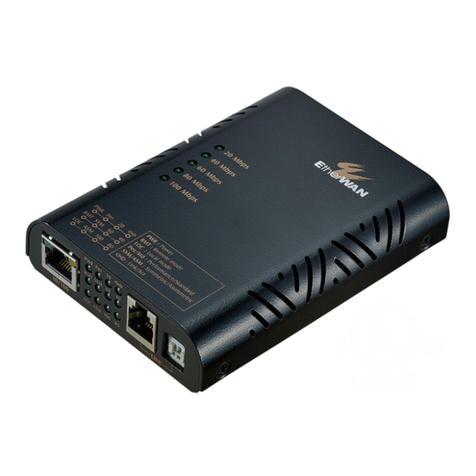
ØOne ED3575 Series hardened managed Ethernet Extender
If items are missing or damaged, notify your EtherWAN
representative. Keep the carton and packing material.
The full product manual can be downloaded from:
https://www.etherwan.com
2What Else You Need
ØCategory 5 or better cable for RJ-45 ports
ØAppropriate cables for fiber and SFP ports
ØTelephone wire (24AWG with minimum 0.5mm diameter) for Ethernet
Extender ports (RJ-11 connector or Terminal Block)
ØPersonal computer with a DB9 straight cable
3Select a Location
ØInstallations: DIN-Rail mount.
ØInstallation must be at a height of at least 6 feet (1.8 meters) above
the floor.
ØIdentify a power source within 6 feet (1.8 meters).
ØChoose a dry area with ambient temperature between -40 and 75ºC (-
40 and 167ºF).
ØKeep away from heat sources, sunlight, warm air exhausts, hot-air
vents, and heaters.
ØBe sure there is adequate airflow.
ØKeep the Ethernet Extender at least 6 ft. (1.83 m) away from the
nearest source of electromagnetic noise, such as a photocopy
machine.
ØThe device can operate at altitudes up to 2000 meters.
4Connect to the Data Ports
Depending on the model, your Ethernet Extender can have the following
ports:
Ø6 10/100BASE-TX ports
Ø2 Gigabit combo ports
Ø2 Ethernet Extender ports (RJ-11 connector or Terminal Block)
10/100BASE-TX Ports
These ports can connect to devices such as an IP surveillance camera.
A. Insert one end of an appropriate cable into a switch port.
B. Connect the other end into the Ethernet port of the device.
C. Repeat steps A and B for each additional device you want to connect
to the switch.
1 Gbps Combo/SFP Ports
If your switch model has combo ports, you can connect them to network
devices such as a computer, printer, network video recorder (NVR),
network storage, or they can connect to the network itself.
Combo ports operate in “either/or” fashion. This means that attaching to
a 1 Gbps combo port renders the equivalent partner combo port
unavailable.
Ethernet Extender Ports
Insert the voice grade copper wire between one pair of Ethernet
Extenders via Ethernet Extender port (RJ-11 connector or Terminal
Block). One device must be set to LOC mode and the other to RMT mode
when two devices are connected.
5Apply Power
The switch has two pairs of power inputs:
ØA 12-48VDC (1.4-0.4A) terminal block
Only one power input is required to operate the switch. However,
redundant power supply functionality is supported.
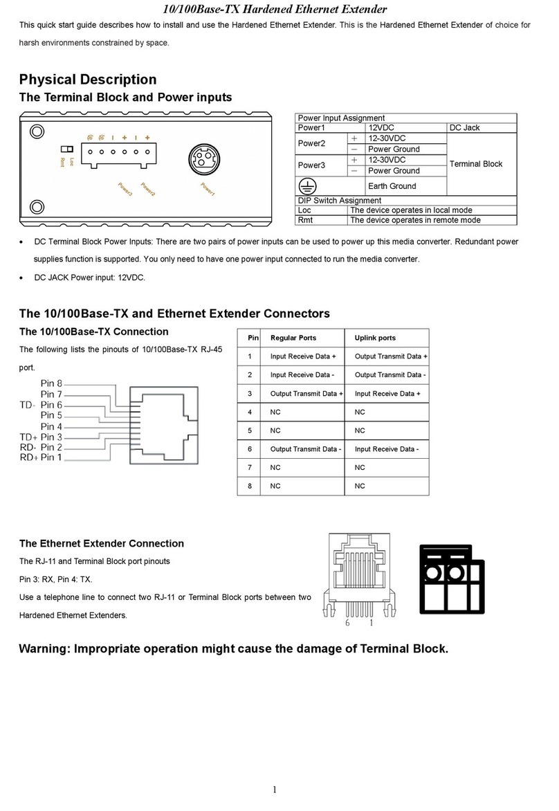
Terminal Block
There are two power inputs on a 12-48VDC (1.4-0.4A) terminal block.
Only one power input is required to operate the Ethernet extender. The
terminal block has 8 terminal posts.
Pin
Description
Power 1
+
12-48VDC (1.4-0.4A)
-
PowerGround
Power 2
+
12-48VDC (1.4-0.4A)
-
PowerGround
Earth Ground
Relay Output Rating
1A@ 24VDC
Power Failure Alarm
A 2-pin terminal block is provided for power failure detection. Do not
connect a power source to these pins.
Power-Up Sequence
When you apply power:
ØAll Link/ACT LEDs blink momentarily.
ØThe Power 1, 2 LED goes ON.
ØLEDs for every port connected to a device flash, as the switch
conducts a brief Power On Self-Test (POST).
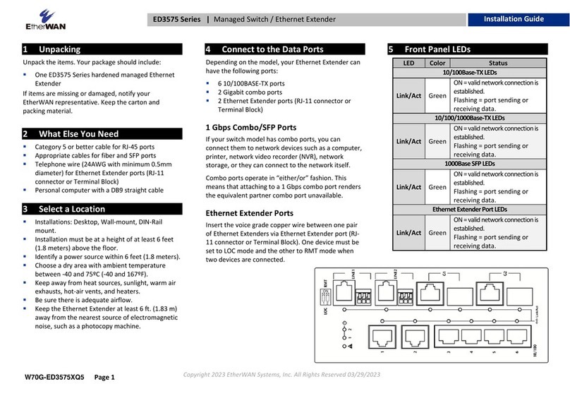
6Front Panel LEDs
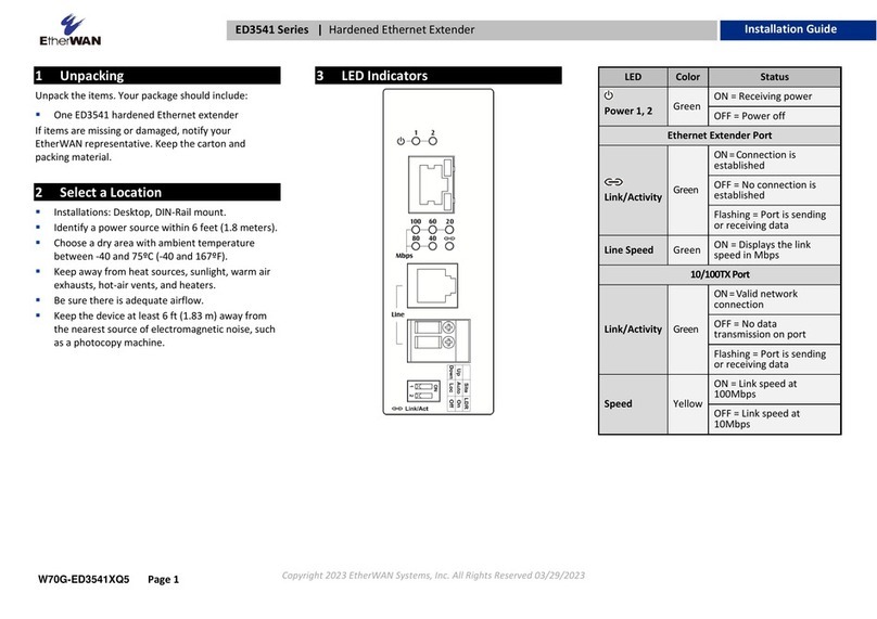
LED
Color
Status
10/100Base-TXLEDs
Link/Act
Green
ON=validnetworkconnectionisestablished.
Flashing= port sendingor receivingdata.
10/100/1000Base-TXLEDs
Link/Act
Green
ON=validnetworkconnectionisestablished.
Flashing= port sendingor receivingdata.
1000BaseSFPLEDs
Link/Act
Green
ON=validnetworkconnectionisestablished.
Flashing= port sendingor receivingdata.
EthernetExtenderPortLEDs
Link/Act
Green
ON=validnetworkconnectionisestablished.
Flashing= port sendingor receivingdata.
ED3575 Managed Ethernet Extender Installation Guide
ED3575 Managed Ethernet Extender Installation
Guide
Copyright 2020 EtherWAN Systems, Inc. Page 2
All Rights Reserved
ED3575V2
02/04/2020
W70G-ED3575XQ5
7DIP Switch
Pin
ON
OFF
DIP Switch 1
RMT mode
LOC mode
DIP Switch 2
RMT mode
LOC mode
Note: Reboot the device to let DIP switch changes take effect.
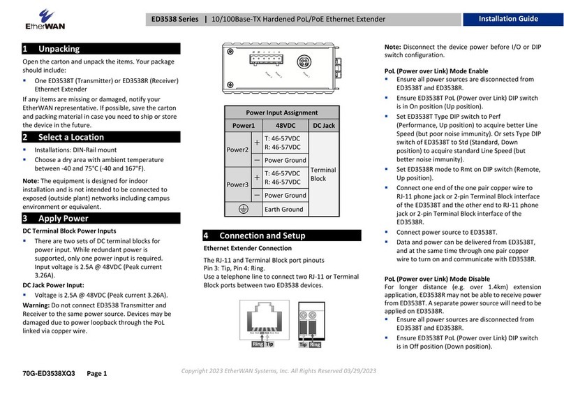
Ethernet Extender Connection
The RJ-11 and Terminal Block port pinouts
Pin 3: Tip, Pin 4: Ring.
Use a telephone line to connect two RJ-11 or Terminal Block ports
between two Hardened Ethernet Extenders.
8Managing the Device
Connect a PC to an available switch port using an appropriate cable, or
use a serial cable to connect to the console port. The IP address of VLAN1
is 192.168.1.10.
The device can also be configured through the Graphical User Interface.
In a web browser, navigate to http://192.168.1.10 and log in.
The default login is “root,” and the default password is blank.
Power wiring information:
Use cable type - AWG (American Wire Gauge) 12-24 and the
corresponding pin type cable terminals. Tighten terminal screws with a
torque value of 7 lb-in. Do not use excessive force when fixing wiring.
The rating of the power wire used must be at least 105°C.
USE COPPER CONDUCTORS ONLY.
If the equipment is used in a manner not specified by the manufacturer,
the protection provided by the equipment may be impaired.
WARNING – Explosion hazard. Do not disconnect the terminal block while
the circuit is live or unless the area is known to be free of ignitable
concentrations.
For repair or maintenance needs, contact EtherWAN directly.
9Other Information
DIN-Rail Assembly Startup, and Dismantling
ØAssembly: Place the media converter on the DIN rail from above using
the slot. Push the front of the device toward the mounting surface
until it audibly snaps into place.
ØStartup: Connect the supply voltage via the terminal block to start
the switch
ØDismantling: Pull out the lower edge
10 Repair and Replacement
Repair and replacement service can be registered at
https://www.etherwan.com/support/rma-request-form
Complete all of the fields on the online form and click submit.
-Before sending in a product for RMA service, please double-check
the following items:
-See if the problem has been addressed in EtherWAN's FAQ database
-Ensure that the device has power and that the power LED indicator
is lit
-Make sure that the product is connected to the network, and that
there is not a problem with the data cable
-Check that the firmware version is the most recent
-Try restoring the device to its factory default settings
Informations de câblage d'alimentation:
Utilisez le type de câble - AWG (American Wire Gauge) 12-24. valeur de
couple de 7 lb-in.
Le calibre du fil d'alimentation utilisé doit être d'au moins 105°C.
DESTINÉ À ÊTRE UTILISÉ AVEC DES CONDUCTEURS EN CUIVRE SEULEMENT.
Si la méthode d'utilisation de l'équipement diffère de celle décrite par le
fabricant, la protection assurée par l'équipement risque d'être altérée.
Contactez-nous pour l'entretien ou la reparation.
AVERTISSEMENT - RISQUE D'EXPLOSION. NE PAS DÉBRANCHER PENDANT
QUE LE CIRCUIT EST SOUS TENSION OU À MOINS QUE L'EMPLACEMENT NE
SOIT EXEMPT DE CONCENTRATIONS INFLAMMABLES.
繁體中文:
線材資訊和注意事項
1. 線材規格需選⽤ 12-24 AWG 和選⽤相對應接頭,接線端螺絲鎖緊軸扭
⼒值為7 lb-in ,請勿過度⽤⼒鎖緊。
2. 線材規格⾄少要 105°C。
3. 線材需為銅導體。
4若設備未依照製造商指定的⽅式使⽤,則設備提供的保護可能會受到損
害。
简体中文
线材资讯和注意事项
1. 线材规格需选⽤12-24 AWG 和选⽤相对应接头,接线端螺丝锁紧轴扭
⼒值为 7 lb-in ,请勿过度⽤⼒锁紧。
2. 线材规格⾄少要 105°C。
3. 线材需为铜导体。
4. 若设备未按制造商指定的⽅式使⽤,则设备提供的保护可能会受到损
害。
日語
注意事項:
1. 推奨する電線の仕様は 12-24AWG と対応するコネクター、ネジの適正な締付
けトルクは 7 lb-in です。
2. 電線の推奨仕様は 105°C 以上です。
3. 電線は銅以外の導体を禁⽌します。
4. メーカー推奨以外の⽅法で設備を使⽤する場合、損壊を与える可能性があり
ます。
Note: The switch can be extremely hot after running under full
load for a while. Please use protective gloves when dismantling or
adjusting the switch.
Remarque: Le commutateur peut êtreextrêmement chaud après avoir
fonctionnéà pleine charge pendantun certain temps. Veuillez utiliser des
gants de protection lors du démontage ou du réglage de l'interrupteur.
Manufacturer information:
ETHERWAN SYSTEMS, INC.
4F-7,No. 79, Sec. 1, Xintai 5thRoad, Xizhi District, New Taipei City
221,Taiwan

Other EtherWAN Extender manuals

EtherWAN ED3538 User manual

EtherWAN

EtherWAN ED3538 User manual

EtherWAN ED3501 User manual

EtherWAN

EtherWAN ED3501 User manual

EtherWAN ED3541 User manual

EtherWAN

EtherWAN ED3541 User manual

EtherWAN ED3238 User manual

EtherWAN

EtherWAN ED3238 User manual

EtherWAN EX3101 User manual

EtherWAN

EtherWAN EX3101 User manual

EtherWAN ED3331 User manual

EtherWAN

EtherWAN ED3331 User manual

EtherWAN ED3575 Series User manual

EtherWAN

EtherWAN ED3575 Series User manual

EtherWAN EMC1600 Series User manual

EtherWAN

EtherWAN EMC1600 Series User manual

EtherWAN ED3501 User manual

EtherWAN

EtherWAN ED3501 User manual

EtherWAN ED3638 User manual

EtherWAN

EtherWAN ED3638 User manual

EtherWAN ED3538 User manual

EtherWAN

EtherWAN ED3538 User manual

EtherWAN ED3541 User manual

EtherWAN

EtherWAN ED3541 User manual

EtherWAN ED3238 User manual

EtherWAN

EtherWAN ED3238 User manual

EtherWAN ED3638 User manual

EtherWAN

EtherWAN ED3638 User manual

EtherWAN ED3501 User manual

EtherWAN

EtherWAN ED3501 User manual

EtherWAN ED3141 User manual

EtherWAN

EtherWAN ED3141 User manual

EtherWAN ED3541 User manual

EtherWAN

EtherWAN ED3541 User manual

EtherWAN ED3538 User manual

EtherWAN

EtherWAN ED3538 User manual

Popular Extender manuals by other brands

TP-Link AC1900 Quick installation guide

TP-Link

TP-Link AC1900 Quick installation guide

MuxLab 500757 Quick installation guide

MuxLab

MuxLab 500757 Quick installation guide

Black Box IC408A user manual

Black Box

Black Box IC408A user manual

Optivisus HE05BT manual

Optivisus

Optivisus HE05BT manual

Black Box Wizard ACU50 A Series user guide

Black Box

Black Box Wizard ACU50 A Series user guide

REI EX-330-K user manual

REI

REI EX-330-K user manual

SureCall Force7 Industrial user guide

SureCall

SureCall Force7 Industrial user guide

TERK Technologies LF-30S owner's manual

TERK Technologies

TERK Technologies LF-30S owner's manual

ENFORCER MVE-AH010Q manual

ENFORCER

ENFORCER MVE-AH010Q manual

Quancom ISA user guide

Quancom

Quancom ISA user guide

Renkforce 94 23 57 operating instructions

Renkforce

Renkforce 94 23 57 operating instructions

LevelOne KVM-9006 user manual

LevelOne

LevelOne KVM-9006 user manual

Manhattan 525695 user manual

Manhattan

Manhattan 525695 user manual

HDanywhere XTND4K100TPC manual

HDanywhere

HDanywhere XTND4K100TPC manual

StarTech.com USB2G4LEXT2 instruction manual

StarTech.com

StarTech.com USB2G4LEXT2 instruction manual

Network Technologies Incorporated ST-C6FOUSB4K-LC product manual

Network Technologies Incorporated

Network Technologies Incorporated ST-C6FOUSB4K-LC product manual

Hunter 9043 user manual

Hunter

Hunter 9043 user manual

PESA PRO-HDMI-CAT user manual

PESA

PESA PRO-HDMI-CAT user manual

manuals.online logo
manuals.online logoBrands
  • About & Mission
  • Contact us
  • Privacy Policy
  • Terms and Conditions

Copyright 2025 Manuals.Online. All Rights Reserved.