PAT EI65 User manual

L-B B5L0082/PAT 031-300-190-015 REVISION D 04/15/99
ANGLE-LENGTH-RADIUS-LOAD
INDICATOR SYSTEM
EI 65
OPERATOR'S AND CALIBRATION
MANUAL
Link-Belt
Construction Equipment
LATTICE BOOM CRANES


GENERAL INFORMATION
L-B B5L0082/PAT 031-300-190-015 REVISION D 04/15/99
i
NOTICE
The information in this document is subject
to change without notice.
PAT makes no warranty of any kind with regard
to this material, including, but not limited
to the implied warranties of merchantability
and fitness for a particular purpose.
PAT shall not be liable for errors contained herein
or for incidental or consequential damages in
connection with the furnishing, performance
or use of this manual.
This document contains proprietary information
which is protected by copyright. All rights are
reserved. No part of this document may be
photocopied, reproduced, or translated to
another language without prior consent of PAT.


OPERATOR’S SECTION
L-B B5L0082/PAT 031-300-190-015 REVISION D 04/15/99
1
Table of Contents
OPERATOR’S SECTION
1. GENERAL INFORMATION...................................................................................................................................... 1
2. WARNINGS.................................................................................................................................................................. 1
3SYSTEM DESCRIPTION ...................................................................................................................................... 2
3.2 OPERATING CONSOLE ............................................................................................................................................... 4
3.3 CONTROL IDENTIFICATION........................................................................................................................................ 5
4PROGRAMMING PROCEDURE ......................................................................................................................... 8
4.1 STARTUP PROCEDURE........................................................................................................................................ 8
3.1.1 Setting of Boom Angle Presets.................................................................................................................... 13
3.1.2 Setting of Boom Height Presets .................................................................................................................. 16
6. OPERATION.............................................................................................................................................................. 21
7. SERVICE AND MAINTENANCE ........................................................................................................................... 21
8 TROUBLESHOOTING.............................................................................................................................................. 22
CALIBRATION SECTION
1GENERAL INFORMATION ............................................................................................................................... 24
2WARNINGS........................................................................................................................................................... 24
3ESSENTIAL INFORMATION AND SETUP FOR CALIBRATION:............................................................. 25
3.1 PRIOR TO POWERING UP THE SYSTEM VERIFY ALL WIRING. ALL UNUSED CHANNELS MUST BE OCCUPIED WITH
DUMMY SIGNALS MEETING THE FOLLOWING REQUIREMENTS........................................................................................ 25
3.1 MECHANICALLY SET THE LENGTH AND ANGLE SENSORS AS FOLLOWS: (SEE APPENDIX A. MECHANICAL
ADJUSTMENT FOR SENSORS)......................................................................................................................................... 25
3.1.1 Setting the line rider output voltage. ............................................................................................. 28


OPERATOR’S SECTION
L-B B5L0082/PAT 031-300-190-015 REVISION D 04/15/99
1
OPERATOR’S SECTION
1. GENERAL INFORMATION
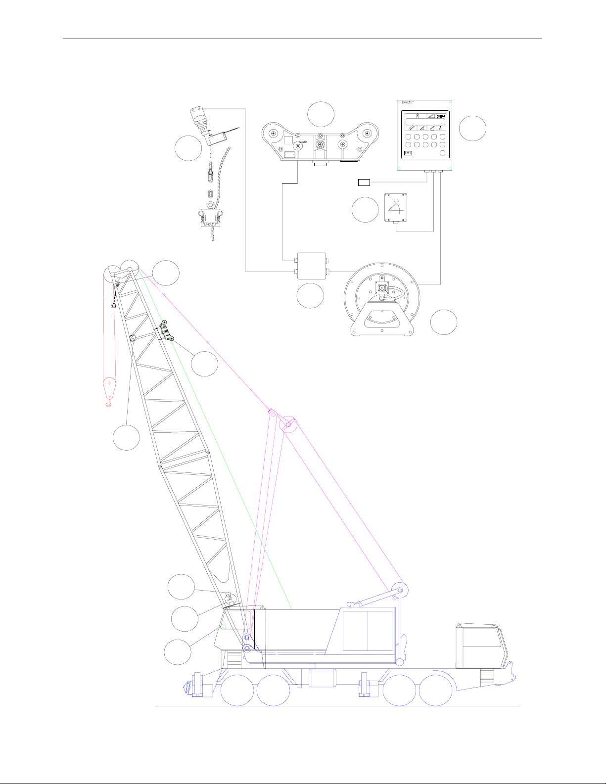
The PAT Length-Angle-Radius-Load Indicator System EI 65 has been designed to provide the
crane operator with the essential information required to enable the machine to be used
within its design parameters. The EI 65 System indicates the length and angle of the boom,
tip height, working radius and the total calculated weight being lifted by the crane.
Using various sensing devices, the EI 65 System warns the crane operator of certain
approaching hazardous conditions which could occur during the operation of his crane.
The purpose of this operator’s manual is to provide information to help him operate, maintain
and troubleshoot the PAT System.
The manual contains the system description, operating, and calibration information.
2. WARNINGS
• The EI 65 is an operational aid that warns a crane operator of certain approaching
hazardous conditions that could cause damage to equipment and personnel.
• The device is not, and shall not be, a substitute for good operator judgment, experience
and use of accepted safe crane operating procedures.
• The responsibility for the safe operation of the crane shall remain with the crane operator
who shall ensure that all warnings and instructions supplied are fully understood and
observed.
• Prior to operating the crane, the operator must carefully and thoroughly read and
understand the information in this manual to ensure that he knows the operation and
limitations of the indicator and crane.
• Proper functioning is dependent upon proper daily inspection and observations of the
operating instructions set forth in this manual.
Always refer to operational instructions and load charts provided by the
crane manufacturer for specific crane operation and load limits.

EI65 OPERATOR’S AND CALIBRATION MANUAL Operator’s Section
L-B B5L0082/PAT 031-300-190-015 REVISION D 04/15/99
2
3 SYSTEM DESCRIPTION
The PAT EI 65 System consists of an operating console with central micro processor unit,
length/angle sensor, force transducers and anti-two block switches.
Boom length and boom angle are registered by the length/angle sensor, mounted inside the
cable reel which is mounted on the boom. The boom length is measured by the cable reel
cable that also serves as an electrical conductor for the anti-two block switches.
The crane load is measured by running line tensiometers attached to the upper side of the
boom.
3.1 System Function
After ignition of the engine, the system starts with an automatic test of all lamps, the audible
alarm and the complete system.
After the system has passed through the system test without errors, the system will request
the operator to confirm the boom and jib configuration data. This allows the operator to
compare the system configuration with the actual crane configuration. (see Section 4.1).
After the operator confirms the system configuration, the console will indicate, on the display
(13), the actual load, tip height, boom length, boom angle, and radius.

OPERATOR’S SECTION
L-B B5L0082/PAT 031-300-190-015 REVISION D 04/15/99
3
Fig. 1: Components of the PAT System EI 65
5
6
2
3
1
4
1
2
3
4
6
5112000
120. 47.5 81.0 16
88.5
EI6
1. EI65 Console
2. Cable Reel
3. An
g
le Sensor
4. Junction Box
5. Linerider
6. A2B Switch

EI65 OPERATOR’S AND CALIBRATION MANUAL Operator’s Section
L-B B5L0082/PAT 031-300-190-015 REVISION D 04/15/99
4
3.2 Operating Console
The console has 2 functions:
• Terminal for input of instructions and information to the system by the crane operator
• Display of crane data and information
The operating console is located in the operator’s cabin in front of the operator. This unit
contains different displays and controls that are described in Section 3.3.
TARE
STOP LIMIT
OK
SELECT
112000lbs
120.0 47.5 81.016
88.5
EI65
12
11
10
789
6
3
2
5
1
4
13
LIMIT
1 Overload Alarm Light
2 Anti-Two Block Alarm Light
3 Limit Alarm Light
4 Audible Alarm
5 Button “Horn OFF” and
Alarm Light
6 Button “SELECT”
7 Button “Reevings/Hoist”
8 Button “LIMIT”
9 Button “TARE”
10 Button “OK”
11 Button “DOWN”
12 Button “UP”
13 Data Display

OPERATOR’S SECTION
L-B B5L0082/PAT 031-300-190-015 REVISION D 04/15/99
5
3.3 Control Identification
The above figure illustrates the controls and displays of the EI 65 Operating Console. The
numbers of the illustration correspond to the numbers in the following list, which describes
the function of each control.
1 Overload Alarm Light
The red Overload Alarm Light (1) will light up when the preprogrammed load
limit is reached. At the same time the Audible Alarm (4) will sound and the
Limit Alarm Light (3) and the alarm light in the button Horn-Off (5) will light up.
The corresponding crane movements will be stopped (Option).
2 Anti-Two Block Warning Light
The red Anti-Two Block Warning Light (2) will light up when the anti-two block
limit switch contacts open, indicating that a two-blocking condition is
approaching. At the same time the Audible Alarm (4) will sound and the alarm
light in the button Horn-Off (5) will light up.
The following crane movements will be stopped simultaneously: hoist up,
telescope out, boom down (Option).
3 Limit Alarm Light
The Limit Alarm Light (3) will light up when one of the preprogrammed limits are
reached. The limits are minimum and maximum limits of boom angle, boom
length, boom height, working radius. At the same time the Audible Alarm (4)
will sound and the alarm light in the button Horn-Off (5) will light up.
The corresponding crane movements will be stopped (Option).
4 Audible Alarm
The Audible Alarm (4) is located on the bottom side of the console. It
sounds during the following conditions:
• Approaching two-block condition
• Preset angle, height, length or radius limits are reached
• Preset load limit is reached
• System error.
The alarm can be silenced for 15 seconds by pushing the button (5).
STOP
LIMIT

EI65 OPERATOR’S AND CALIBRATION MANUAL
L-B B5L0082/PAT 031-300-190-015 REVISION D 04/15/99
6
5 Button “Horn Off” and Alarm Light
The Button “Horn Off” (5) allows the audible alarm to be silenced for approx.
15 seconds by pressing this button. At the same time the corresponding Alarm
Light (5) goes out.
6 Button “Select”
The button “Select” (6) is used for indicating and setting the values of the
Operating conditions.
After pressing this button the display indicates a part of the “Select Menu”. It
is possible to move through the different points and pages of the menu step by
step by pushing the button “DOWN” (11).
The procedure for indicating and setting the Operating Conditions is described in Section 4.2
7 Button “Reevings/Hoist”
The button “Reevings/Hoist (7) is used for setting the number of reevings (parts
of line) and selecting the hoist winch.
After pressing the button one time the operator is requested to enter the actual
number of parts of line by using the button “Up” (12) and “Down” (11).
After pressing the button two times the operator can select the actual hoist winch by using
the button “Up” (12) and “Down” (11).
The procedure for setting the reevings and selecting the hoist winch is described in Section
4.2
8 Button “Limit”
The button “Limit” (8) is used for activating the setting procedure of the preset
limits. This limits are minimum and maximum limits of boom length, boom
angle, boom height, working radius and maximum limit of load.
The procedure for setting the limits is described in Section 4.3
SELECT
LIMIT

OPERATOR’S SECTION
L-B B5L0082/PAT 031-300-190-015 REVISION D 04/15/99
7
9 Button “Tare”
The button “Tare” (9) is used to indicate the net load on the display. Net load is
the actual load, less lifting tackle and hook block. The button “Tare” has to be
activated before lifting.
After pushing the button “Tare” (9) before lifting the load display will be set to
zero (tare) and the lamp in the button lights up. After lifting a load the load display shows the
net load (pay load).
The net load display will return to the normal load display when the button “Tare” (9) is
pressed a second time.
10 Button “OK”
This button (10) is used to confirm values and data which are used as input for
the system. The instruction to use this button will always be given on the
display.
11 Button “Down”
The button “Down” (11) is used to get an decrease of a numerical value at the
display during the programming and setting procedures and to move through
the different menus in “Down”-direction. The instruction to use this button will
be given on the display.
12 Button “Up”
The button “Up” (12) is used to get an increase of a numerical value at the
display during the setting procedure of limits and operating conditions.
TAR E
OK

EI65 OPERATOR’S AND CALIBRATION MANUAL
L-B B5L0082/PAT 031-300-190-015 REVISION D 04/15/99
8
13 Display
The Display (13) will show technical information as well as operating information and
instructions for the operator.
120.0
112000lbs 88.5
81.047.5 16
During crane operation the readout will display the actual load, the tip height, the boom
length, the boom angle, the working radius, the selected hoist winch and the number of
reevings (parts of line). In case of a system error an error code is displayed in place of the
reevings.
During the setting procedure of the Operating Conditions and the limit setting procedure the
display shows the setting values and information for the operator.
4 PROGRAMMING PROCEDURE
During the startup phase the PAT System EI 65 automatically starts with a programming
procedure which relies on the correct entry by the crane operator.
This procedure consists of three parts:
• Startup Procedure
• Setting operating configuration of the crane
• Setting the preset limits
For simple operation, the computer guides the operator through the procedure step by step.
The operator has to read the information displayed and is instructed to answer questions by
using appropriate buttons of the keyboard. During each step of the procedure particular
button lights will come on to identify the possible choices for the step.
4.1Startup Procedure
After ignition of the engine the system starts the Startup Procedure with a self test.
During the Startup Procedure the crane operator will confirm the preset configuration stored
in system memory as described below. The operator will compare the preset operating
configuration values with the actual crane configuration.

OPERATOR’S SECTION
L-B B5L0082/PAT 031-300-190-015 REVISION D 04/15/99
9
If there is a difference between the indicated and the actual condition, the operator must
correction those values by completing step 1 to 14 in Section 4.2.2.
The system stores the preset values for minimal 2 hours when the crane voltage is switched
off. After a loss of the preset values the operator will need to reset these values.
The display shows the previously programmed boom and jib
configuration. The crane operator can compare the preset
Operating Configuration Values with the actual crane
configuration. To confirm the displayed values push the button “OK” (10).
To change the configuration values go to one of the following sections. If the system
configurations are correct, go to Section 5 PRE-OPERATION INSPECTION.
• Section 4.2 will allow the operator to change all crane configurations.
• Section 4.2.1 will allow the operator to quickly change Reeving only
• Section 4.2.2 will allow the operator to quickly to change Hoist selection only.
Setting Operating Configuration of the Crane
STEP 1
To enter new values the button “Select” (6) has to be pushed.
The DOWN (11) button can be pressed to skip a step in the following procedure. When the a
particular step is skipped, the configured values of that step remain the same as the
confirmed values in Section 4.1
STEP 2
The operator is requested to enter the boom configuration. To enter
new boom data he has to push the button “OK” (10).
Push Button “OK” (10) for next step.
To continue with the previously entered boom configuration the button DOWN (11) has to be
pushed.
Step 3 to 9 will be skipped, when the button “DOWN” is pressed.
STEP 3
The operator is requested to push the button “DOWN” (11) if the
crane is equipped with a boom extension.
If the crane is equipped only with a main boom (without jib or boom extension) the button OK
(10) has to be pressed.
Step 5 to 9 will be skipped, when the button “OK” is pressed.
MB 115.0 J1 85.0
J2 50.0 0J 15.0 1
SELECT BOOM?
PUSH ↓OR OK
MAIN BOOM?
PUSH ↓OR OK

EI65 OPERATOR’S AND CALIBRATION MANUAL
L-B B5L0082/PAT 031-300-190-015 REVISION D 04/15/99
10
STEP 4
The display shows the previously programmed or default length of the
main boom.
To enter a new main boom length, the operator has to select the value by pushing the
buttons “UP” (12) or “DOWN” (11).
Go to Step 10 HOIST SELECT.
STEP 5
The operator is requested to enter the jib configuration.
To enter new jib data, push the button “OK” (10).
Push Button “OK” (10) for next step.
If the operator wants to continue with the previously programmed jib configuration or the
default values he has to push the button “DOWN” (11).
STEP 6
The display shows the previously programmed or default length of jib
1.
To enter a new jib length, the operator has to select the value by pushing the buttons “UP”
(12) or “DOWN” (11). If no jib 1 is used the value 0.0 has to be selected.
If the operator wants to continue with the displayed length of jib 1 he has to confirm by
pushing the button “OK” (10).
Push Button “OK” (10) for next step.
Note: Jib 1 is a boom extension with fixed length and without offset angle.
STEP 7
The display shows the previously programmed or default length of the
jib 2.
To enter a new jib length, the operator has to select the value by pushing the buttons “UP”
(12) or “DOWN” (11). If no jib 2 is used the value 0.0 has to be selected.
If the operator wants to continue with the displayed length of jib 2 he has to confirm by
pushing the button “OK” (10).
Push Button “OK” (10) for next step.
BOOM LGTH?
PUSH ↓↑ OR OK
JIB SELECT?
PUSH ↓OR OK
JIB LGTH_1: 45
PUSH ↓↑ OR OK
JIB LGTH_2: 25
PUSH ↓↑ OR OK

OPERATOR’S SECTION
L-B B5L0082/PAT 031-300-190-015 REVISION D 04/15/99
11
Note: Jib 2 is an extension with fixed length and with different offset angles.
STEP 8
The previously programmed or default offset angle of jib 2 is
displayed.
To enter a new offset angle, the operator has to select the value by pushing the buttons “UP”
(12) or “DOWN” (11).
If the operator wants to continue with the displayed offset angle of jib he has to confirm by
pushing the button “OK” (10).
Push Button “OK” (10) for next step.
STEP 9
If the main boom length is correct, push the button “DOWN” (11). To
change the main boom length the button OK (10) has to be pressed.
Confirm jib values entered in Steps 6 to 9, by pressing the button “OK”.
STEP 10
Step 11 will be skipped, if the crane is not equipped with an Auxiliary
Hoist.
The crane operator is requested to enter the actual hoist winch.
Push Button “OK” (10) for next step.
If the operator wants to continue with the previously used or default hoist he has to push
button “DOWN” (11).
Step 11 will be skipped, when the button “DOWN” is pressed.
STEP 11
To select either the Main Hoist or the Auxiliary Hoist the operator
has to use the button “DOWN” (11).
If the operator wants to continue with the displayed hoist he has to
confirm by pushing the button “OK” (10).
Push Button “OK” (10) for next step.
STEP 12
The crane operator is requested to enter the number of reevings
(parts of line) being used.
JIB OFFSET_2: 15
PUSH ↓↑ OR OK
MAIN BOOM?
PUSH ↓OR OK
HOIST SELECT?
PUSH ↓OR OK
MAIN HOIST?
PUSH ↓OR OK
AUXILIARY HOIST?
PUSH ↓OR OK
REEVING?
PUSH ↓OR OK

EI65 OPERATOR’S AND CALIBRATION MANUAL
L-B B5L0082/PAT 031-300-190-015 REVISION D 04/15/99
12
Push Button “OK” (10) for next step.
If the operator wants to continue with the previously programmed or default number of
reevings he has to push button “DOWN” (11). Step 13 will be skipped, when the button
“DOWN” is pressed.
STEP 13
The display shows the previously programmed or default number of reevings (parts of line).
To enter a new number of reevings the operator has to select the value by pushing the
buttons “UP” (12) or “DOWN” (11).
If the operator wants to continue with the displayed number of reevings (parts of line) he has
to confirm by pushing the button “OK” (10).
Push Button “OK” (10) for next step.
STEP 14
The Setting Procedure is completed. The crane operator has the possibility to accept the
conditions programmed on Step 1 to 12, or to correct the values.
For correction of the preset conditions the Button “DOWN” (11) has to be pushed. In this
case the system starts again the Startup Procedure.
If the displayed conditions are O.K. the crane operator has to push Button “OK” (10).
Then the display will show the actual crane data.
Setting of Reevings
The setting procedure can be activated by the operator by pushing the button “Reevings/Hoist
Winch” (7).
After pushing the button one time an asterisk will appear on the display beside the
number of reevings, indicating that the procedure of setting the reevings is
activated. To enter a new number of reevings the operator has to select the value
by pushing the buttons “UP” (12) or “DOWN” (11).
If the operator wants to continue with the displayed number of reevings (parts of
line) he has to confirm by pushing the button “OK” (10).
After pushing the button “OK” (10) the procedure for Number of Reevings is completed and
the display will show the actual crane data.
4.2.2 Selecting the Hoist Winch
The procedure for selecting the hoist winch can be activated by the operator by pushing the
button “Reevings/Hoist Winch” (7) two times.
16 *

OPERATOR’S SECTION
L-B B5L0082/PAT 031-300-190-015 REVISION D 04/15/99
13
After pushing the button two times an asterisk will appear on the display
beside the symbol for the hoist winch.
Select either the main hoist “UP” (12) or the auxiliary hoist using the button
“DOWN” (11).
Select the actual used hoist winch, and confirm by pushing the button “OK” (10).
The display will show the actual crane data.
Activating and Setting of Preset Limits
The PAT System EI 65 is equipped with the following presets:
• limit for maximum hook load
• limits for maximum and minimum boom angle, boom length and working radius.
The operator has the possibility to activate the load limit and/or the maximum and minimum
limit of one of the above geometric dimensions. The limit which is activated is identifiable by
an blinking colon.
For simple operation the computer guides the operator through the procedure step by step.
The operator has to read the information displayed and is instructed to answer questions by
using appropriate buttons of the keyboard. During the Setting Procedure the lamp in the
particular button lights up.
After a loss of the preset values the system sets the values of the Preset Limits on maximum
or minimum and deactivates all preset limits. This can happen, when the system is longer
than 2 hours without supply voltage.
The Activating and Setting Procedure can be started by the crane operator by pushing the
Button LIMIT (8).
3.1.1 Setting of Boom Angle Presets
STEP 1
This message appears after pushing the Button “LIMIT” (8). For activating the Setting
Procedure of Boom Angle Limits the operator has to push Button “DOWN” (11).
Push Button “DOWN” (11) for next step.
STEP 2
To select the Boom Angle Preset Programming Procedure push the button “OK” (10).
Push Button “OK” (10) for next step.
To skip the angle preset limit push the button “DOWN” (11).
Step 3 to 6 will be skipped, when the Button DOWN is pressed. The system continues with
Radius Limit Preset Programming Procedure (see Section 4.3.2)
*

EI65 OPERATOR’S AND CALIBRATION MANUAL
L-B B5L0082/PAT 031-300-190-015 REVISION D 04/15/99
14
STEP 3
The actual value of the Minimum Boom Angle Preset is displayed.
To enter a new value of the Minimum Boom Angle Preset, the operator has to push the
button “UP” (12) for increase and the button “DOWN” (11) for decrease the displayed value.
If the crane operator wants to continue with the displayed value, he has to confirm by
pushing the button “OK” (10).
Push Button “OK” (10) for next step.
STEP 4
The actual value of the Maximum Boom Angle Preset is displayed.
To enter a new value of the Maximum Boom Angle Preset, the operator has to push the
button “UP” (12) for increase and the button “DOWN” (11) for decrease the displayed value.
If the crane operator wants to continue with the displayed value, he has to confirm by
pushing the button “OK” (10).
Push Button “OK” (10) for next step.
STEP 5
For verification of the previously set values the Maximum and Minimum Boom Angle Preset is
displayed.
Push Button “OK” (10) for next step.
STEP 6
The Setting Procedure for the Boom Angle Presets is completed. The display shows the actual
crane data. To remind the crane operator of the activated Boom Angle Preset the display of
the actual boom angle shows a intermittent colon.
Other manuals for EI65
1
Table of contents
Other PAT Construction Equipment manuals
Popular Construction Equipment manuals by other brands

Avantco
Avantco 180 Operator's manual

Avantco
Avantco Dozer blade 1400 Operator's manual

Avantco
Avantco A36304 Operator's manual for Attachment

Haufftechnik
Haufftechnik HSI150 MA Series installation instructions

Haufftechnik
Haufftechnik MSH Basic-FUBO-E-SR4 Assembly instruction

Toro
Toro MMX-658K-P Operator's manual