PAT DS 50 Programming manual

1
TSM DS 50-003/REV.C/031-300-190-003/04-20-07
DS50 TROUBLE SHOOTING MANUAL LEVEL 3
Overload Warning
System DS 50
Trouble Shooting Manual
Level 3
- Calibration Adjustments
-
Grove

2
TSM DS 50-003/REV.C/031-300-190-003/04-20-07
DS50 TROUBLE SHOOTING MANUAL LEVEL 3
NOTICE
The information in this document is subject to change without notice.
PAT makes no warranty of any kind with regard to this material, including,
but not limited to the implied warranties of merchantability and fitness for
a particular purpose.
PAT shall not be liable for errors contained in this manual or for incidental
or consequential damages in connection with the furnishing, performance,
or use of this manual. This document contains proprietary information
which is protected by copyright. All rights are reserved.
No part of this document may be photocopied, reproduced or translated
to another language without the prior written consent of PAT.

3
TSM DS 50-003/REV.C/031-300-190-003/04-20-07
DS50 TROUBLE SHOOTING MANUAL LEVEL 3
Table of contents
Item Content Page
1. Introduction to troubleshooting the PAT Overload Warning System DS50
1.1 System outline 6
1.2 System operation 8
1.3 Troubleshooting care 9
2.1 The hand terminal 11
2.2 The hand terminal connection 13
3.1 The start up menu 14
3.2 Displaying data and messages 15
3.3 The test program 17
3.4 The on-line mode 19
4 Adjusting calibration data 21
5 Identify the problem 22
6 Adjusting overload cut off factor 23
7 Adjusting empty hook load display 25
8 Adjusting radius display under load 27
9 Adjusting load display 29
10 Transferring EEPROM data 31
11 Error code messages 41
12 Removing test and calibration Equipment 45

4
TSM DS 50-003/REV.C/031-300-190-003/04-20-07
DS50 TROUBLE SHOOTING MANUAL LEVEL 3
CAUTION !
The use of the equipment and the procedures in the following sections allow data
change of the microprocessor system DS50 and its calibration.
Therefore only trained and authorized service personnel shall proceed with the
procedures and data adjustments described in this manual. Incidental errors in the
calibration or software change may result in a fatal accident. Always verify software
change or calibration change results.

5
TSM DS 50-003/REV.C/031-300-190-003/04-20-07
DS50 TROUBLE SHOOTING MANUAL LEVEL 3
NOTICE
THIS TROUBLE SCHOOTING MANUAL “DS 50 - LEVEL 3” IS DESIGNED TO
ASSIST THE SERVICE OR MAINTENANCE PERSONNEL IN ADJUSTING THE
EXISTING CALIBRATION DATA AND TRANSFERRING CALIBRATION DATA INTO
A REPLACEMENT DS 50 CENTRAL UNIT.
THIS TROUBLE SHOOTING MANUAL DOES NOT REPLACE ANY CALIBRATION
INSTRUCTION. THEREFORE IT SHOULD NOT BE USED AS A CALIBRATION
MANUAL.
IN ORDER TO PERFORM THE ADJUSTMENTS IN THIS TROUBLE SHOOTING
MANUAL YOU REQUIRE A SPECIAL TOOL SET. THE TOOL SET CONSISTS
OF A HAND TERMINAL AND A SET OF CABLES FOR COMMUNICATING WITH
THE DS50 CPU BOARD. WE ASSUME THAT REGULAR MAINTENANCE AND
SERVICE TOOLS AND A DIGITAL VOLTMETER ARE AVAILABLE ON SITE.
THIS TROUBLE SHOOTING MANUAL DS 50 - LEVEL 3- IS THE CONTINUATION
OF TROUBLE SHOOTING MANUAL DS 50 - LEVEL 1- AND -LEVEL 2- AND
ASSUMES THE KNOWLEDGE OF THE CONTENT OF THE PREVIOUS LEVELS .
WE SUGGEST THAT ONLY TRAINED MAINTENANCE AND SERVICE PERSONNEL
PROCEED WITH THE TROUBLE SHOOTING DESCRIBED IN THIS MANUAL.

6
TSM DS 50-003/REV.C/031-300-190-003/04-20-07
DS50 TROUBLE SHOOTING MANUAL LEVEL 3
1. INTRODUCTION TO TROUBLESHOOTING THE PAT DS 50
1.1. SYSTEM OUTLINE
The PAT Overload Warning System Model DS 50 is designed to disable the
boom down and up, hoist up and tele out crane functions when the crane
attempts to lift over its limits. These limits are specified in the load capacity
chart provided by the crane manufacturer.
When the DS 50 system detects an overload condition the following crane
functions are disabled immediately.
a. telescope out
b. boom up and boom down
c. hoist up
To remove the overload condition the operator must achieve a safe working
condition. This can be achieved by lowering the load and repositioning the
crane or decreasing the radius by telescoping in. Observe that the radius can
not be decreased by lifting the boom. The boom up function is disabled while
attempting to overload the crane.
The system design allows you to operate the crane in an emergency situation
or system failure without the DS 50 system in operation. In this situation leave
the crane electric switch in the off position and press the override button while
you operate the crane manually. The DS 50 Overload Warning System is not
operative and can not warn the operator with the electric power switch in off
position.
Warning
Bypassing the DS 50 Overload Warning system
may results in property damage, injury or death.
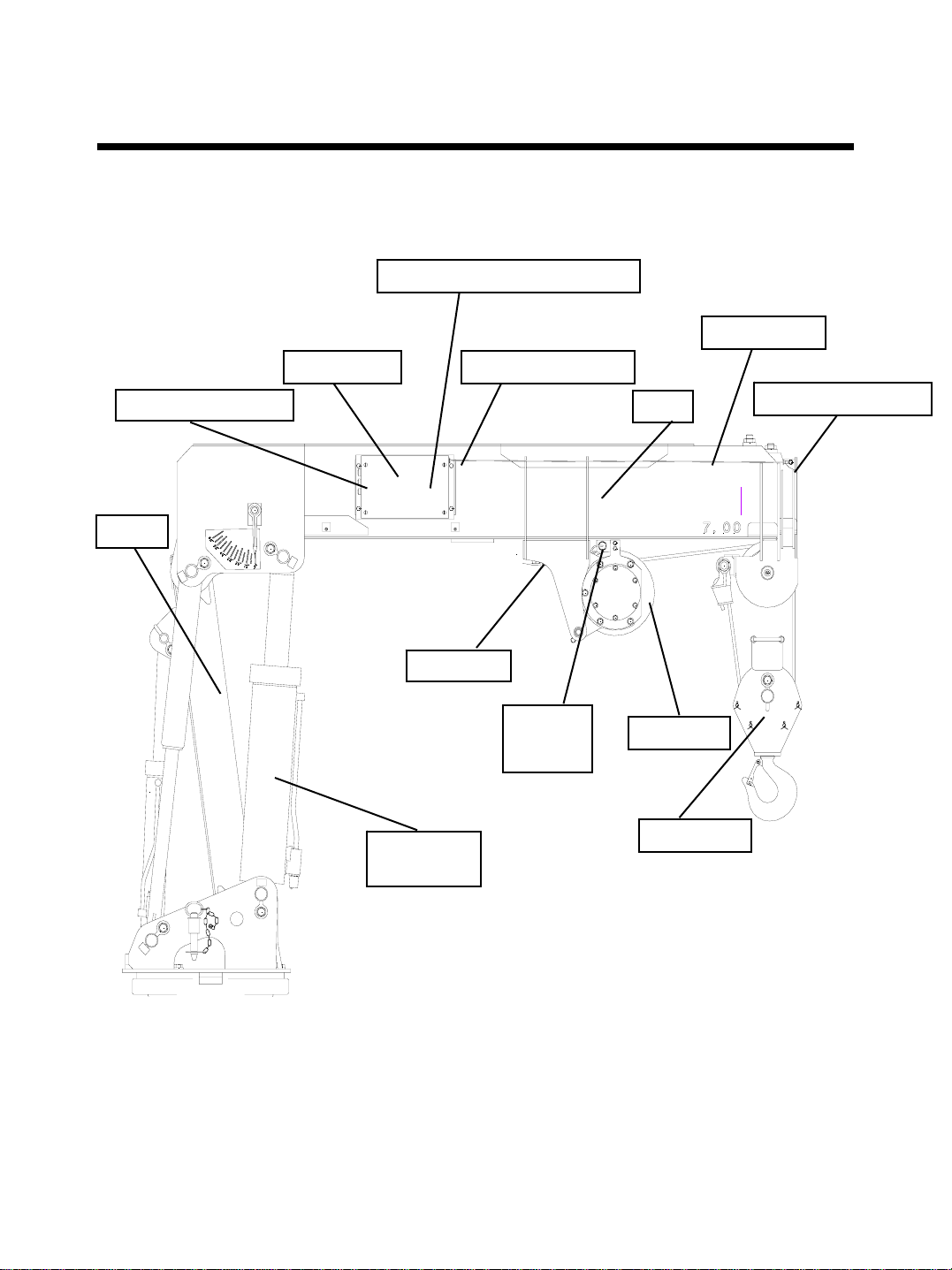
The DS 50 system contains a central unit with integrated length and angle
sensor. The load cell is supporting the hoist drum and used to measure the
load on hook.

7
TSM DS 50-003/REV.C/031-300-190-003/04-20-07
DS50 TROUBLE SHOOTING MANUAL LEVEL 3
1. INTRODUCTION TO TROUBLESHOOTING THE PAT DS 50
DS 50 SYSTEM
LENGTH CABLE
BOOM
LOAD CELL
PROXIMITY
SWITCH
BOOM LIFT
CYLINDER
HOOK BLOCK
MAST
LENGTH CABLE MOUNT
LENGTH CABLE ENTRY
HOIST DRUM
CABLE CONNECTORS
LENGTH SENSOR - UNDER COVER-
Note: The drawing shows
the model FMTV-W.
The FMTV-C has only single
line capability.
DRAWING 1.1 - SYSTEM LOCATION (FMTV-WRECKER)

8
TSM DS 50-003/REV.C/031-300-190-003/04-20-07
DS50 TROUBLE SHOOTING MANUAL LEVEL 3
1. INTRODUCTION TO TROUBLESHOOTING THE PAT DS 50
1.2 SYSTEM OPERATION
The Microprocessor Central Unit operates as the control center of the system.
The length cable is connected to the boom nose. During telescoping the length
cable spools off a drum which turns the length potentiometer using a gear
assembly. The length potentiometer is a variable resistor which varies linearly
with the boom length. An angle sensor is built into the central unit which senses
the boom angle. The load cell provides the signal to calculate the load on hook.
The proximity switch located on the hoist drum switches to a different calibration
factor during spooling off the hoist rope. This will allow a steady load calculation
and compensates for the difference in the lever arm. All together the signals get
processed in the central Microprocessor unit where actual and rated load are
compared. The system de-energizes a relay and disables the appropriate crane
functions when the actual load exceeds the rated load by more than 10%.

9
TSM DS 50-003/REV.C/031-300-190-003/04-20-07
DS50 TROUBLE SHOOTING MANUAL LEVEL 3
1. INTRODUCTION TO TROUBLESHOOTING THE PAT DS 50
1.3. Troubleshooting Care
• Keep in mind while troubleshooting high quality electronic
components to use caution and necessary care while testing and
measuring DS 50 components and circuits of the crane electric's.
• Tools and test equipment must be in good order and shall be inspected
on a regular basis.
• Follow all safety instructions according to crane manufacturer’s
handbooks and safety instructions. Obey recommended practice and
safety standards applying to the job site.
• Secure the working area prior to testing and servicing the system.
• Never remove the load cell without firm support holding the hoist drum.
• Never let the length cable snap back to the central unit. The length
sensor drum is under high tension.
Warning
DS 50 Overload Warning System service and repair work
shall be performed by trained and authorized personnel only.

10
TSM DS 50-003/REV.C/031-300-190-003/04-20-07
DS50 TROUBLE SHOOTING MANUAL LEVEL 3
1. INTRODUCTION TO TROUBLESHOOTING THE PAT DS 50
Crane power switch Crane electric
junction box
Outrigger extend
proximity switches-
FMTV-Cargo only.
Hook block storage position
DRAWING 1.2 - Crane storage position
Note: The drawing shows
the model FMTV-W.
The FMTV-C has only single
line capability.
Caution !
Crane is shown folded for transportation.
For lifting operations the mast has to be in full upright position
and the hook lifted out of the transportation storage.

11
TSM DS 50-003/REV.C/031-300-190-003/04-20-07
DS50 TROUBLE SHOOTING MANUAL LEVEL 3
2.1 THE HAND TERMINAL
The key board of the hand terminal is divided in three main areas.
Refer to drawing 2.1.1 and locate the keys which are described in the text below.
• Numerical key pad: Used to enter numerical data.
• Alphabetical key pad: Used to enter commands (letters).
• Function keys: Used to correct, delete or confirm an entry or display.
Some keys are assigned to special hand terminal functions.
•Control LEDs: The LEDs above the numerical key pad light up to confirm the
on-line status and various key function. In example the green
file LED lights up after the shift key was pressed.
• The display (LCD): Indicates data and messages.
The use of the hand terminal in connection with the DS 50 System is described in
the course of the following instructions. Part of the hand terminal is a cable. The
DB9 connector at the end of the cable shall be connected to the DS 50 main board.
Refer to section 2.2 and drawing 2.2.1 and 2.2.2 for hand terminal connection.
CAUTION: The DB 9 connector is wired especially for the DS 50 interface.
Do not attempt to connect the hand terminal to any device other
than the DS 50.

12
TSM DS 50-003/REV.C/031-300-190-003/04-20-07
DS50 TROUBLE SHOOTING MANUAL LEVEL 3
2.1 THE HAND TERMINAL
Plus / Minus
Drawing 2.1.1

13
TSM DS 50-003/REV.C/031-300-190-003/04-20-07
DS50 TROUBLE SHOOTING MANUAL LEVEL 3
2.2 THE HAND TERMINAL CONNECTION
In order to connect and use the hand terminal for data read-out or data adjustment
the DS 50 hardware must be prepared as follows:
• Switch the truck power off. Remove both the DS 50 central unit cover and the
CPU board cover carefully as described in manual level 1&2.
• Plug the female DB 9 connector of the hand terminal cable into the male DB 9
connector on the DS50 CPU board.
• Secure the hand terminal cable with cable ties to avoid cable stress or pulling off
connections while operating the crane.

14
TSM DS 50-003/REV.C/031-300-190-003/04-20-07
DS50 TROUBLE SHOOTING MANUAL LEVEL 3
3.1 THE START UP MENU
Follow the instructions described in section 2.2 to connect the on-line equipment.
Switch the truck power on. A cursor appears on the top left of the hand terminal
display and the red ‘online’ LED lights up. After the DS 50 system has passed the
self test routine, the display shows the start up menu. Refer to drawing 3.1.
The following letters allow the user to select the desired program.
• D = Data output to PC terminal mode. Not used for hand terminal operation.
• H = Data output to hand terminal.
• O = Select the on-line mode. The on-line mode must be selected to adjust
calibration data.
• T = Select the test mode. The test mode allows the user to initialize the EEPROM
prior to a new calibration only and to test the digital inputs such as the function
of the hoist layer switch.
Caution: Do not initialize a calibrated system. Initialization of the EEPROM
results in loss of calibration data and a recalibration becomes
necessary.
Refer to the appropriate section in this manual to distinguish what letter key of the
start up menu to select.
Drawing 3.1.1

15
TSM DS 50-003/REV.C/031-300-190-003/04-20-07
DS50 TROUBLE SHOOTING MANUAL LEVEL 3
3.2 DISPLAYING DATA AND MESSAGES
Follow the instructions in section 2.2 and 3.1
In order to identify the need for a data adjustment, internally calculated data must
be compared with the actual measured data.
The DS 50 is an overload shut down system and is not classified as a scale. The
consideration of government specified tolerances is part of the trouble shooting
process. Crane and truck manufacturing tolerances do not allow calibrating an
overload shut down system with 0% tolerance.
To select the read out of geometrical data, load data and error messages press
the >H< key of the alphabetical key pad. The following information is now displayed.
Refer to drawing 3.2.1 to identify the displays described in the text below.
• Utilization of the lifting capacity in percentage. Overload cut off should be active
between 100% and 110%. The sample drawing 3.2.1 indicates an utilization of 84%.
• Maximum load capacity ( in lb/1000) for the actual boom position. The sample
drawing 3.2.1 indicates a maximum load capacity of 5,000 lb.
• Actual load on hook (in lb/1000). Note that the hook is not part of the load. The
sample drawing 3.2.1 indicates an actual load of 4,200 lb.
• Main boom length (in ft). The distance between the center of the boom pivot pin and
and the center of the sheave wheel pin.The sample drawing 3.2.1 indicates a
main boom length of 14.2 ft.
Refer to table below for fully retracted and fully extended boom length indication.
Indicated length
Crane model: retracted extended
FMTV Cargo 7.3 15.7
FMTV Wrecker 7.3 18.4
FMTV FRSH 7.3 18.4
• Main boom angle (in degree) in reference to the horizontal line. The sample drawing
3.2.1 indicates a boom angle of 65.5 degree.
• Radius (in ft.). Radius is defined as the distance between center line of crane rotation
and the center line of the load freely suspended. The sample drawing 3.2.1 indicates
a radius of 15.7 ft.
• In the event of a malfunction, an overload condition, or an out of load chart condition,
the radius display becomes replaced by the Error message. Refer to the error code
list to decode the message.

16
TSM DS 50-003/REV.C/031-300-190-003/04-20-07
DS50 TROUBLE SHOOTING MANUAL LEVEL 3
3.2 DISPLAYING DATA AND MESSAGES
Drawing 3.2.1

17
TSM DS 50-003/REV.C/031-300-190-003/04-20-07
DS50 TROUBLE SHOOTING MANUAL LEVEL 3
3.3 THE TEST PROGRAM
The test program is designed to initialize the E-EPROM prior to a new calibration
and to test the function of the digital inputs such as the hoist layer switch function.
Press the key >T< to start the test program. Refer to drawing 3.3.1 and 3.3.2.
The program allows to select the test routine:
• Press 4 to initialize the E-EPROM
CAUTION: DO NOT INITIALIZE A CALIBRATED SYSTEM. YOU WILL LOSE
ALL CALIBRATION DATA IF YOU PRESS THE >Y< KEY AFTER
THE MESSAGE “OVERWRITE ? (Y/N)”. ALWAYS CONFIRM WITH
THE >N< KEY IF YOU ENTERED THE ROUTINE BY MISTAKE.
WHEN TRANSFERRING DATA TO A REPLACEMENT SYSTEM IT
MAY BECOME NECESSARY TO INITIALIZE THE REPLACEMENT
SYSTEM BEFORE DATA TRANSMISSION.
• Press 8 to test digital inputs
The hand terminal display indicates the actual status of the digital input.
DI 1
1
A >1< means the digital input is powered on and a >0< means the digital input is
not powered on. In the example above the DI 1 is powered by the hoist layer switch.
Switch off the hoist layer switch by lowering the hoist and you can see the >1<
changing to >0<. For correct adjustment of the switch refer to documentation in
level 1 &2.
To return to the main menu press the >ESC< key or the letter key for the program
you wish to select.

18
TSM DS 50-003/REV.C/031-300-190-003/04-20-07
DS50 TROUBLE SHOOTING MANUAL LEVEL 3
3.3 THE TEST PROGRAM
Drawing
3.3.1
Drawing 3.3.2

19
TSM DS 50-003/REV.C/031-300-190-003/04-20-07
DS50 TROUBLE SHOOTING MANUAL LEVEL 3
3.4 THE ON-LINE MODE
The calibration equipment and the system must be switched into on-line mode for
calibration adjustments. From the start up menu, select the on-line mode by pressing
the >O< key. The hand terminal displays the message >SYSTEM READY<. The
operating mode code and the actual length step >OM= 0101, LS = 7.33< confirms
the operation of the on-line mode.
Refer to the example in drawing 3.4.1.
A calibration adjustment is possible for a length step only. A length step is the main
boom length shown in each load chart column.
You can exit the on-line mode any time. Exit the on-line mode by pressing the
>SHIFT< key and then the > ^ < key. The hand terminal confirms with the message
>End online mode<.
Once in the start up display of the on-line mode there are two calibration functions
available.
• Press the >U< key to change calibration data for the actual length step.
• Press the >V< key to change load calibration data for the actual length step.
Refer to the flowchart diagrams of this manual for detailed information how to use
the two calibration functions.
• Press the >K< key to return to the start up menu. Message > End online mode<.
• Press either >U< or >V< key to switch between the two calibration functions.

20
TSM DS 50-003/REV.C/031-300-190-003/04-20-07
DS50 TROUBLE SHOOTING MANUAL LEVEL 3
3.4 THE ON-LINE MODE
Drawing 3.4.1
Other manuals for DS 50
4
Table of contents
Other PAT Construction Equipment manuals