PATHFINDER 2400 TRS User manual

1
Maverick Boat Group
3207 Industrial 29th St. • Fort Pierce, Florida 34946
(772)-465-0631 •Pathfinderboats.com
2400 TRS Owner’s Manual
Revised May 2020

2
Maverick Boat Group
3207 Industrial 29th St. • Fort Pierce, Florida 34946
(772)-465-0631 •Pathfinderboats.com
Welcome to the Pathfinder Family!
Thank you for choosing a Pathfinder boat to transport
you to your angling dreams. We believe the
Pathfinder 2400 TRS is the best all-purpose boat on
the market, and we’re sure that you’ll be completely
satisfied with the unmatched performance, quality
and fishability of your new boat.
We value your input, not just at the time of the sale,
but throughout the entire boat ownership period, and
we’ve taken steps to allow you to share that
information. Over the next year or so, you will receive
at least two questionnaires to fill out and return.
Be sure to visit our website www.pathfinderboats.com
to find information on company events like our
Owner’s Tournaments and Corporate Calendar. You’ll
find a wealth of information on our Forum, where you
can ask questions, get answers and join other
Pathfinder owners to discuss all applications of your
boat. We’re proud to have you as a member of the
Pathfinder family!
Tight lines and screaming drags!
Scott Deal
President and CEO

3
Maverick Boat Group
3207 Industrial 29th St. • Fort Pierce, Florida 34946
(772)-465-0631 •Pathfinderboats.com
Table of Contents
2400 TRS Specifications...........................................................................................................................4
Pre-Operation Checklist.........................................................................................................................5
Maintenance & Cleaning .....................................................................................................................6
Engine Break-In Period ...........................................................................................................................7
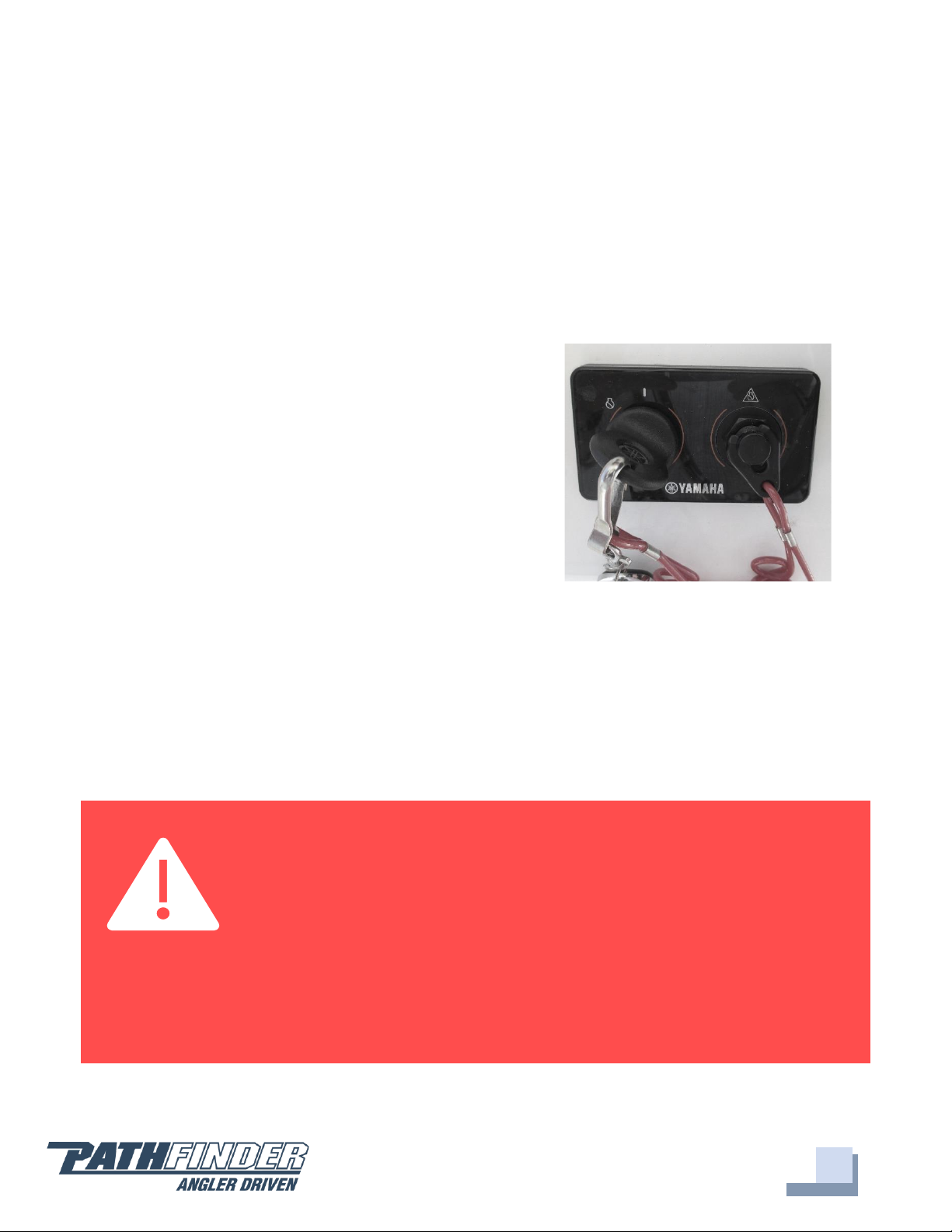
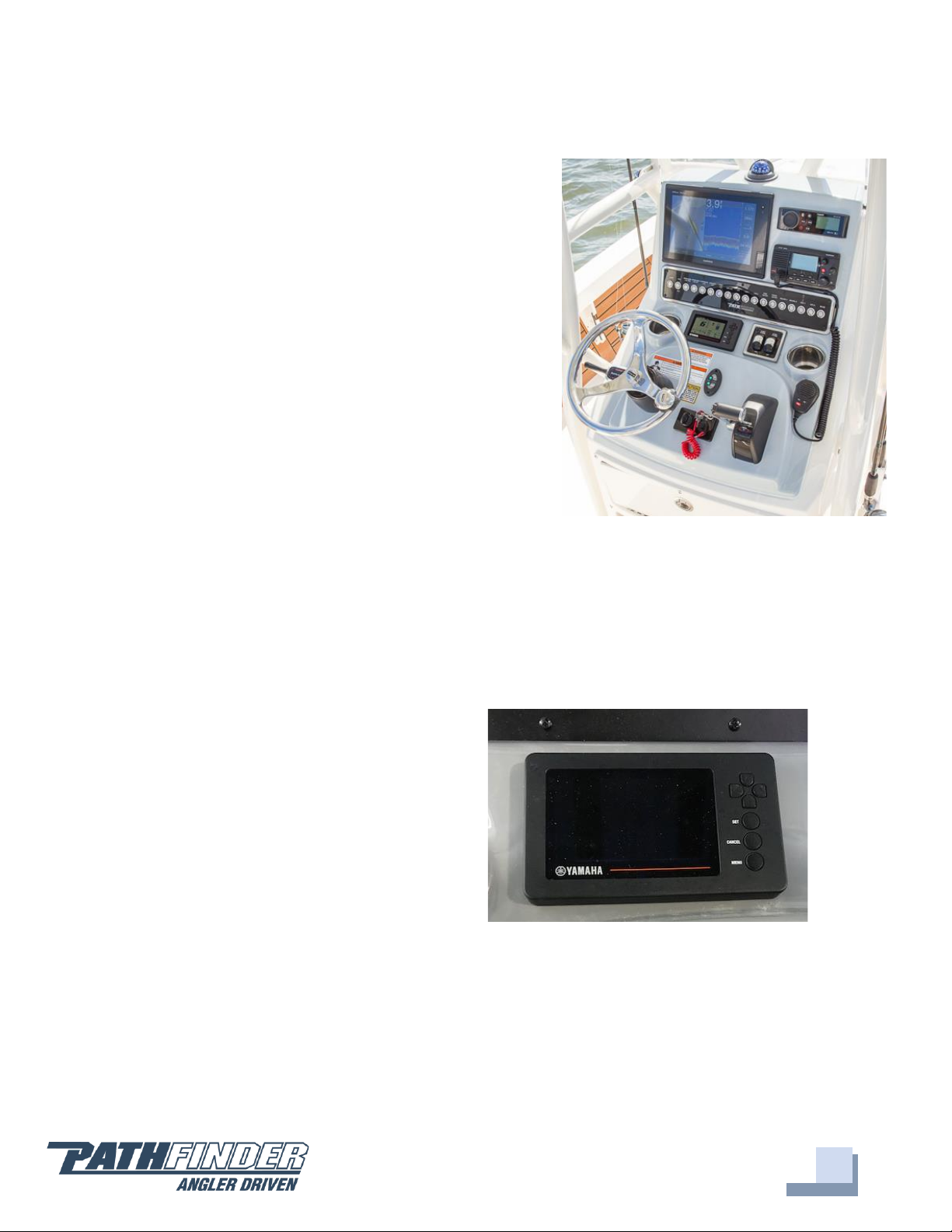
Switch Panel & Helm...............................................................................................................................8
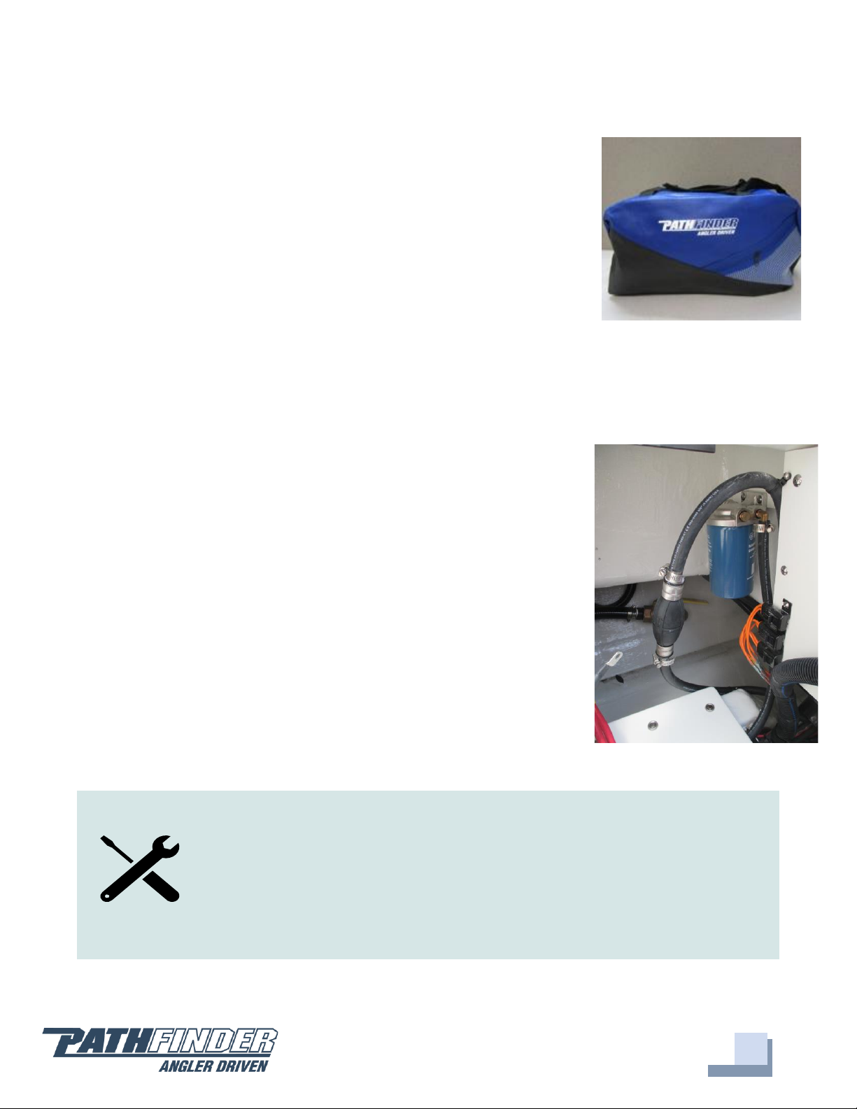
Fuel-Water Separator & Drain ..............................................................................................................9
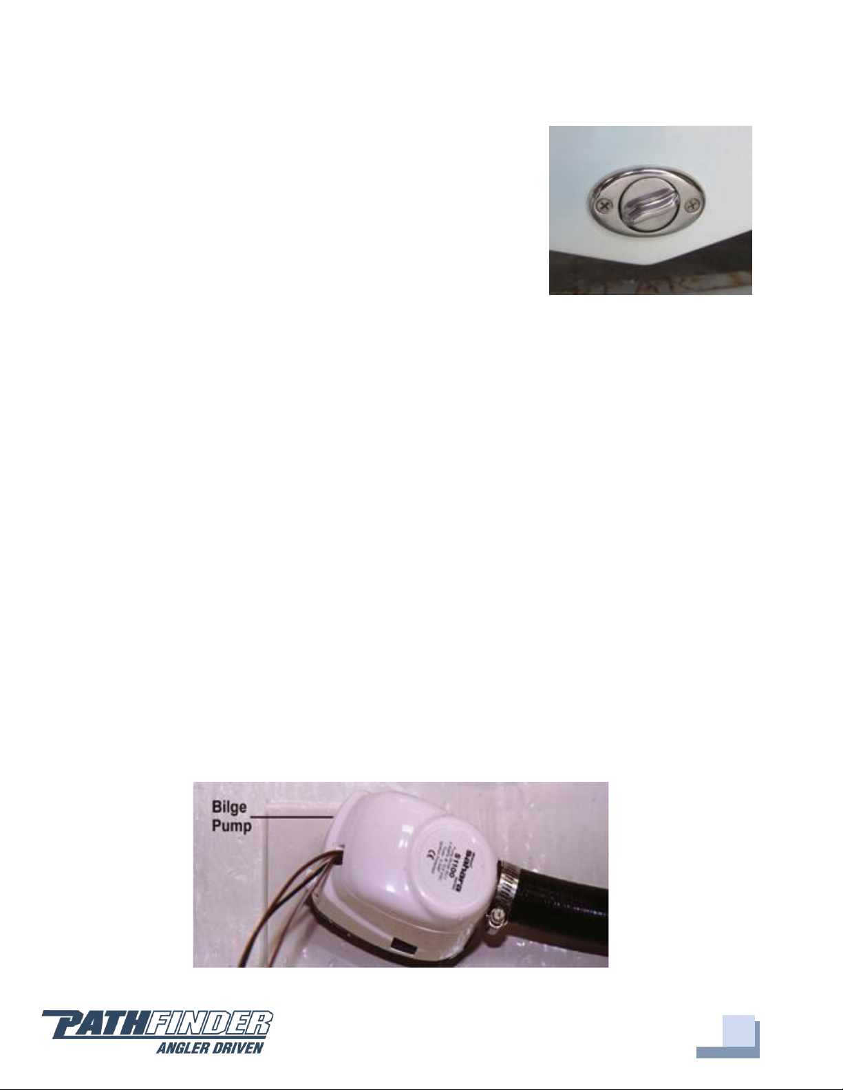
Bilge ...........................................................................................................................................................10
Systems......................................................................................................................................................12
Backing Plates & Trolling Motor Wiring.............................................................................................13
Battery Switch and Breaker Panel.....................................................................................................13
Ladder & Props.......................................................................................................................................15
Fuel System ..............................................................................................................................................16
Self-Bailing Cockpit & Livewell ...........................................................................................................16
Wiring.........................................................................................................................................................18
Standard Features .................................................................................................................................20
Optional Features ..................................................................................................................................23
2400 TRS Optional Trolling Motor with Battery Charger and Wire Routing.............................24
2400 TRS Reinforcements .....................................................................................................................25
2400 TRS Power Pole Plate...................................................................................................................26
Upholstery Care & Cleaning Guide..................................................................................................27
Warranty...................................................................................................................................................28

4
Maverick Boat Group
3207 Industrial 29th St. • Fort Pierce, Florida 34946
(772)-465-0631 •Pathfinderboats.com
2400 TRS Specifications
L.O.A......................................................................................................................23’ 11”
BEAM......................................................................………………….…...................8’ 06”
DRAFT..........................................................................................................................12”
DEADRISE……………………………………………………………………………….15 DEG.
WEIGHT W/ ENGINE.........................................................................................3,300 LBS.
FUEL CAPACITY....................................................................................................73 GAL.
MAXIMUM H.P............................................................................................................300
MAX CAPACITIES…………………………………..…...…….…9 PERSONS OR 2,000 LBS.
Aft Deck Flip-Up
Seating (Rigging
Access Under Seat)
Anchor Locker
Leaning
Post
Locking Rod
Storage
Cooler with
Seat Cushion
Livewell
Fuel Fill
Livewell
Console Rod
Rack

5
Maverick Boat Group
3207 Industrial 29th St. • Fort Pierce, Florida 34946
(772)-465-0631 •Pathfinderboats.com
Pre-Operation Checklist
We recommend you print this document and store it at the helm station.

6
Maverick Boat Group
3207 Industrial 29th St. • Fort Pierce, Florida 34946
(772)-465-0631 •Pathfinderboats.com
Maintenance & Cleaning
Maintenance
Pathfinder advises owners that maintenance and repairs should be performed at an
authorized Pathfinder Dealer. The following information is general in nature and should
not be considered a repair manual or guidelines set forth by Maverick Boat Group.
Cleaning
Each Pathfinder boat is constructed using the finest materials and components
available. However, no material is immune to the ravages of the saltwater environment.
After each use, your boat should be rinsed thoroughly with fresh water. Refer to page 27
for upholstery care and cleaning instructions. A light coat of lubricant on metal railing,
screws and electrical connections will help prevent electrolysis. The same holds true for
your trailer. To improve the longevity of your gel coat, it is recommended that you wax
your boat once a year using an approved fiberglass wax.

7
Maverick Boat Group
3207 Industrial 29th St. • Fort Pierce, Florida 34946
(772)-465-0631 •Pathfinderboats.com
Engine Break-In Period
New engines require a period of break-in to allow the surfaces of the moving parts to
mate evenly. Different engines require different break-in periods and methods. For
instructions on break-in methods, refer to your Yamaha Engine Owner’s Manual for the
correct break-in procedures and times for your model engines.
Engine Stop Switch
If activated, the spring-loaded engine stop switch
will automatically shut down the engine during
emergency situations to prevent uncontrolled or
unattended operation. Certain emergency
conditions (e.g., turbulent water, wakes,
unanticipated movement) may impair a person’s
ability to operate the craft safely. The switch, located
on the helm, must have the safety lanyard attached
at its base. This activates the protective shutdown
circuitry.
Securely attach the other end of the lanyard to the operator of the boat. If the operator
moves, falls or is at an unsafe distance from the steering wheel, tension on the lanyard
will pull it from the switch. When the lanyard is removed, the engine stop switch is
released and automatic engine shutdown occurs.
Engine Stop Switch
DANGER:
An engine stop switch system that is not used or does not function
properly can cause death or serious injury. DO NOT operate the boat if
the engine stop switch system does not function properly. Go to a
Pathfinder Dealer to have this resolved immediately.
The lanyard should be securely attached to the boat operator at all times that
the engine is on.

8
Maverick Boat Group
3207 Industrial 29th St. • Fort Pierce, Florida 34946
(772)-465-0631 •Pathfinderboats.com
Switch Panel & Helm
Switch Panel & Helm
At the helm of your Pathfinder, you have a main
switch panel, which is located above the steering
wheel. This panel controls your lights, horn,
accessories, livewell, and your bilge. The bilge switch
is an on-demand switch to run your bilge pump and
is used as a backup in case the float indicator in your
bilge pump becomes clogged.
To the right of the steering wheel you have your two
trim tab switches, which are standard on the 2400
TRS. The boat also comes standard with a compass
mounted on top of the console.
Gauges
The instrument panel on your Pathfinder 2600 TRS is composed of one Yamaha digital
gauge and a series of dual activation switches. The switches come with accessory plug-
ins for wiring additional electronics, pumps or electrical circuits.
The standard digital gauge includes a
Yamaha tachometer and a Yamaha
speedometer on one screen. The
tachometer has several built-in features
including an engine temperature monitor,
oil level monitor and engine trim indicator.
The speedometer includes a digital readout
of the speed, an hour meter, trip meter and
clock. For more information on the
specifics of your Yamaha gauges, see your
Yamaha owner's manual.
Helm & Switch Panel
Yamaha Digital Gauge

9
Maverick Boat Group
3207 Industrial 29th St. • Fort Pierce, Florida 34946
(772)-465-0631 •Pathfinderboats.com
Pathfinder Duffel Bag
Along with your boat, you received a Duffel Bag with your new
Pathfinder. Inside the Duffel Bag are the following items:
oLarge Livewell Standpipe
oShort Livewell Standpipe
o1.5” Livewell Pacifier Plug
o2 ignition Keys and Emergency Kill Cord /Engine Stop Lanyard
oEngine Start Cord
o1 Garboard Drain Plug
o1 Gas Fill Key
o2 Glove Box Keys
oVarious Accessories Manuals
Fuel-Water Separator & Drain
Fuel-Water Separator
Each Pathfinder 2400 TRS is equipped with a fuel water
separator to ensure maximum performance and protect the
outboard engine from contaminated gasoline. The fuel separator
is a metal, cylindrical unit secured to the transom section of
your starboard aft rigging box.
The fuel separator can be checked by removing it from the
mounting bracket in the rigging locker and dumping it into an
approved waste collection device. If there appears to be an
excessive amount of water, the filter component should be
changed. See your authorized Pathfinder dealer for replacement
parts.
Maintenance Note: Yamaha recommends replacing the 10-
micron fuel filter on new boats after the first 10 hours or 1 month of
operation and every 50 hours or every 6 months thereafter. In
areas of high humidity where water in fuel supplies is a problem or
extensive engine operation occurs, more frequent replacement
may be necessary.
Fuel-Water Separator
Pathfinder Duffel Bag

10
Maverick Boat Group
3207 Industrial 29th St. • Fort Pierce, Florida 34946
(772)-465-0631 •Pathfinderboats.com
Garboard Drain Plug
The garboard drain plug is the small metal plug located at
the lowest point on the hull, at the bottom of the transom
right above the keel. The drain has been designed so that it
can be loosened by hand while the hull is out of the water
for draining. This allows the plug to stay in contact with
the surrounding frame so you’ll never misplace or lose it.
You can completely remove the insert by pulling back and
continue turning in a counter-clockwise motion. It is
manufactured with a rubber seal in place to ensure your bilge is watertight. Always
make sure before putting the boat in the water that this plug is hand tightened firmly.
Excess water in the bilge may be an indication of a problem with this plug or the
automatic bilge pump.
Bilge
Bilge
The bilge of your Pathfinder should always be checked before and after a launch. While
checking the bilge, note that a small amount of water in the bilge is normal. However, a
large amount of water or any signs of fuel or oil requires immediate attention. If such a
situation exists, the boat should be taken to a certified marine technician
immediately. Never pump fuel or oil overboard while your boat is in the
water.
Large quantities of water in the bilge may be an indication of a leak or that the bilge
pump and/or automatic float switch is not functioning properly due to a jam, clog or
electrical issue. The automatic float switch is wired to the 24-hour side of the battery
Drain Plug
Bilge Pump is Mounted to ABS Plastic

11
Maverick Boat Group
3207 Industrial 29th St. • Fort Pierce, Florida 34946
(772)-465-0631 •Pathfinderboats.com
switch through the “BILGE” breaker on the battery switch panel. When functioning
properly, the float switch activates the bilge pump to pump water overboard once water
in the bilge reaches a level that submerges the switch.
If the bilge pump does not come on when the float switch is submerged, attempt to
manually turn it on through your switch panel. If the bilge pump comes on and
evacuates the water, it is clear that the float switch is not functioning properly. If the
bilge pump does not come on via the switch panel, check the breaker on the battery
switch panel to see if a breaker has been tripped. If the breaker has been tripped, reset it
and turn the switch on again, listening for the bilge pump to turn on. Additionally, the
automatic float switch has an independent fuse located by the batteries.
If the bilge pump fails to turn on, turn the battery switch to the OFF position, then
unhook the bilge pump from its cradle by pressing down on the blue tabs on the cradle
and gently turning the top of the pump. You will feel the pump release from the cradle.
The entire bilge pump and wiring should release from the cradle. After removing the
pump, check the underside and impeller areas for miscellaneous items that might clog
the pump. If any obstructions are present remove the debris and set the pump back into
the cradle. Once set back in the cradle, press the blue tab down and rotate the pump
until you feel it snap back in place. Once this is completed you can try to turn the pump
on again.
If the bilge pump still does not turn on, it likely needs to be replaced. It is not
recommended to use your boat if the bilge pump and/or float switch are not functioning
properly.
Note: Your bilge pump is equipped with an anti-airlock nozzle that
exhausts any air that may cause the pump to air lock. It is normal to
see mist or spray escaping while the pump is running as it is still
functioning properly.

12
Maverick Boat Group
3207 Industrial 29th St. • Fort Pierce, Florida 34946
(772)-465-0631 •Pathfinderboats.com
Systems
Ball Valves
Ball valves can be used to serve several purposes. They allow
seawater to enter the boat, in the case of livewells, and they
also act as a safeguard to stop water from entering. To tell
which position a ball valve is in, open or closed, look at the
valve and determine the direction of flow. When the ball
valve handle is in the same position as the direction of flow,
the valve is in the “OPEN” position. When the ball valve
handle appears to cross the direction of flow, the valve is in
the “CLOSED” position.
2400 Deckdrain System
The deckdrain system is equipped with 1 1/2” thru hull fittings through the aft port and
starboard hull sides. These fittings have to be installed lower than the drains in the
cockpit floor so that gravity will allow the cockpit to drain free of water. This puts these
fittings very close to the water line of the hull. These drains are rigged with ball valves
that can be opened and closed to control the flow of water. The ball valves can be
accessed through the pie eyes on the port starboard side of the transom. In the open
position, these ball valves will allow water to flow freely from the cockpit, thus making
the boat “self-bailing”. When closed, no water will be allowed to travel to or from the
cockpit.
2400 Livewell Pump Assembly
The livewell pump assembly is composed of a scoop
strainer mounted to the bottom of the hull, a thru hull
fitting, ball valve assembly, and the pump. As you can
see, the ball valve assembly is in the “OPEN” position.
This is the correct position for the operation of the
livewell.
Livewell Pump Assembly in the “OPEN” Position

13
Maverick Boat Group
3207 Industrial 29th St. • Fort Pierce, Florida 34946
(772)-465-0631 •Pathfinderboats.com
Backing Plates & Trolling Motor Wiring
Backing Plates
The diagrams on pages 25-26 show all the screw-retention backing plates (trolling
motor, T-Top, Leaning Post) originally placed in the deck of a Pathfinder 2400 TRS
during the construction process.
Trolling Motor/Wiring System
Your Pathfinder 2400 TRS comes standard with a 36V trolling motor wiring system. A
trolling motor mounting plate was built into the bow of your Pathfinder during the
manufacturing process. To attach a trolling motor, please go to your nearest Pathfinder
dealer. All trolling motors should be attached by drilling through the mounting plate
with a 13/64” drill bit and 1/4” tap and using 1/4” #20 machine screws. The plate is
designed to accommodate the mounting patterns of all trolling motor brands on the
market currently. See page 24 for optional trolling motor system with battery charger
and wire routing.
Battery Switch and Breaker Panel
The battery switch and main breaker panel is located in the glove box. The top 50-amp
breaker is the main power for the boat, which feeds the switch panel on the helm and its
associated accessories along with engine power. The 7-amp breaker below that is for the
bilge and the remaining two 15-amp breakers are for adding additional accessories.
Between each breaker and its label there is a small LED light which will be illuminated if
that breaker and its corresponding system is receiving power. When the battery switch is
on the “off” position, only the light for the bilge should be on, as the bilge pump and
float switch are wired directly to the batteries so that they remain operational at all
times. (refer to page 10 for bilge pump instructions). When the boat is not in use, it is
recommended to leave the battery switch in the off, “0’, position to ensure that the main
battery is not drained over the long term by minor current flows.
Your Pathfinder is rigged at the factory so that the primary battery or "house battery" is
tied to setting “1” on the battery switch. When the switch is in this position, your main
breaker LED light should be illuminated. If that is not the case, determine if the breaker
has been tripped by pressing in the right side of 50-amp switch labeled with the “I”. This

14
Maverick Boat Group
3207 Industrial 29th St. • Fort Pierce, Florida 34946
(772)-465-0631 •Pathfinderboats.com
will close the circuit and should result in the LED light coming on. In the event there is
still no main power, this could be an indication of a dead battery, loose connection from
this battery to the battery switch, or the need for a new 50-amp breaker.
All Pathfinders are rigged standard with a 36 volt trolling motor wiring system. The
battery switch allows for pulling from one of the trolling motor batteries or a secondary
battery to supplement or totally replace the house battery. In the event that there is not
enough power to crank the engine from battery “1”, turning the battery switch to the
“1+2” position will allow you to pull power from both batteries simultaneously. If this is
required to start the engine, it is recommended to change the switch back to the “1”
position once the engine is running so that the engine’s alternator can recharge the
primary battery.
Battery Access
Easy access to the back of the helm can be achieved by opening
the top dutch door. To access the console floor where the
batteries are kept simply move the cooler and open the lower
door.
Battery Switch
Console Access

15
Maverick Boat Group
3207 Industrial 29th St. • Fort Pierce, Florida 34946
(772)-465-0631 •Pathfinderboats.com
Ladder & Props
Stainless Boarding Ladder
The 2400 TRS comes with the Swim/Dive Platform mounted in the stern of the boat.
This platform provides for an easier and safer entry and exit from the boat. To operate
the platform simply lift the metal ladder from the platform, extend the ladder to its full
length, and let the ladder fall into the water.
Props
Prop selection on your 2400 TRS is determined by your local
Pathfinder Dealer, but all props are based on
recommendations from Pathfinder Boat Company and
Yamaha Marine in order to give your boat maximum overall
performance. The needs of your prop will determine the prop
design and size that best fits your performance requirements.
For instance, a prop with a smaller pitch will increase speed
out of the hole (jumping onto plane) but will produce a
decreased overall speed compared to a prop with a larger
pitch. Four bladed props may increase overall speed or allow
the boat to run shallower, and some props can decrease cavitation at high speeds. Your
individual prop needs will determine the prop design and size that best fits your
performance requirements.
Always inspect the engine and prop prior to launching your boat with the engine off. Key
prop issues include tangled fishing line or other types of debris, cracked blades or fluid
leaking out of the seal. Look for fishing line tangled around the prop or lower unit seal.
Consult your Yamaha Owner’s Manual to address these issues.
Engine Prop
DANGER:
No passenger should attempt to enter or exit the boat by
the ladder or by any other means while the engine is on.

16
Maverick Boat Group
3207 Industrial 29th St. • Fort Pierce, Florida 34946
(772)-465-0631 •Pathfinderboats.com
Fuel System
Fuel System
Your Pathfinder 2400 TRS comes with a 73-gallon aluminum
fuel cell stationed midship between the stringers just below
and in front of the console. The fuel fill receptacle is on the
port gunwale forward of the console. There's also a recessed
fuel overflow vent on the port side of the boat just below the
fuel receptacle.
We regularly pressure test each fuel system when it is initially
received at the factory and until it leaves the factory as a
component on a new boat. Should you experience any fuel related problems or suspect
problems with the fuel system, immediately take your boat to your local Pathfinder
dealer.
Self-Bailing Cockpit & Livewell
Self-Bailing Cockpit
The cockpit on the Pathfinder 2400 TRS is designed to be self-bailing, meaning that all
the water that comes into the cockpit will be directly drained overboard. This keeps the
boat from acquiring standing water and allows the boat to drain at all times, including
while the boat is docked.
DANGER:
Do not smoke while filling the tank. Be sure to turn off the engines
and all electrical equipment when fueling the boat to prevent
accidental discharges of static electricity. Use only the
recommended gasoline (see Yamaha Owner’s Manual). Do not
use fuels with alcohol or alcohol related derivatives that can
cause marine fuel system hoses to deteriorate.
Fuel Fill Receptacle

17
Maverick Boat Group
3207 Industrial 29th St. • Fort Pierce, Florida 34946
(772)-465-0631 •Pathfinderboats.com
Water drains out of the cockpit through the two aft cockpit drains located at each of the
back corners of the cockpit. The drains run water via hoses out of the sides of the hull.
None of this water is drained into the bilge. Refer to page 12 for operation of the ball
valve associated with this system.
The bilge is designed to drain any water entering the inside of the hull. Livewell and
cockpit drains are closed systems that flush water out the drain scuppers in the stern. All
hoses are sealed and double clamped during construction. Continuous or periodic
running of the automatic bilge pump may be an indication of a hose leak or break in a
seal and should be investigated by a Pathfinder Dealer immediately. Refer to page 10 for
further information regarding bilge pump operation and maintenance.
Livewell System
The new and improved livewell system on the 2400 TRS keeps bait alive longer than any
other system on the market. It has a dual inflow system and a unique drain system that
prevents dead zones and quickly expels any harmful chemicals (such as ammonia) from
the water.
The boat is shipped with the shut-off valve turned to the “off” position (at a 90-degree
angle). To start using your livewell, turn the shut-off valve counterclockwise so that it is
in line with the pipe to open the system to water flow. This shut-off valve is also in place
in case of the unlikely event of a leak while out on the
water.
Your Pathfinder 2400 TRS comes with two standpipes
and a pacifier-style drain plug to control water levels
inside the livewell. The smaller standpipe is for use with
crustaceans like shrimp and crabs that prefer a lower
water level. The taller standpipe is for baitfish, and the
drain plug is to hold water or seal the compartment. The
standpipes should be placed in the hole located in the
starboard aft section of the livewell. Make sure that the
standpipe is firmly secured before covering the area with
the plexiglass cover. Make sure that the bigger holes in
the plexiglass cover are at the bottom before it is secured. Secure the cover by twisting
the tabs located on both sides. On rare occasions, the livewell will not pump water even
though the switch is turned on, the system is open and the livewell pump is running. If
that occurs shift the throttle into reverse and back the boat several feet to purge a
Livewell

18
Maverick Boat Group
3207 Industrial 29th St. • Fort Pierce, Florida 34946
(772)-465-0631 •Pathfinderboats.com
possible air pocket in the system. If there appears to be a clog in the drain, remove the
grate and clear the top of the standpipe of any detritus.
Your boat might come with an optional recirculation system. This is a closed system that
recycles the water already within the well. This system is also controlled by a switch on
the switch panel and allows the boat operator to operate the livewell without an outside
feed. This is ideal if you are transporting bait from different water extremes.
Wiring
A wiring diagram of your Pathfinder has been included to help troubleshoot any
electrical problems or to add additional electronics or electrical connections. We
recommend you use a trained marine electrician for all electrical issues.
Inside the console on the starboard side is the ground terminal and the breaker panel is
located in the glove box. All the grounds lead to the ground terminal and then to the
battery via a large diameter black wire.
Always use the recommended breaker/fuse amp sizes. Oversizing or using larger
breakers/fuses than required can lead to electrical shorting and possible damage or
destruction of the entire electrical system.
There are open slots on both the ground block and the breaker panel for additional
electrical hook-ups. The accessory switches should be used for any additional hook-ups
to protect the entire electrical system. All additional electrical hook-ups should be
performed by a qualified marine electrician.
As a standard practice, we run pull cords forward and aft for any additional wiring
needs. For your convenience and ease we have included a nylon rigging string that runs
through the rigging tubes and terminates in the bow. The nylon string will allow you to
easily run any additional wiring through the rigging tubes, thus protecting them from
outside elements. We also run a string aft to the rigging box.
Note: Be sure to turn the shut-off valve to the 90-degree off position
BEFORE doing any work on the livewell pump or plumbing that could
potentially allow the inflow of water. Failure to do so will result in
outside water entering the bilge area.

19
Maverick Boat Group
3207 Industrial 29th St. • Fort Pierce, Florida 34946
(772)-465-0631 •Pathfinderboats.com
Pathfinder Main Harness
To Console
Pin # Function Wire Color AWG
1. Nav Lts (Instrumentation) Grey 16
2. Nav Lts Grey 16
3. Anc Lt (Console) Grey/White 16
4. Anc Lt (T‐TOP) Grey/White 16 Pin C T‐Top Recept
5. Horn Orange/White 16
6. Spreader Lt Blue/Black 16 Pin A T‐Top Recept
7. Overhead Lts Blue/Green 16 Pin B T‐Top Recept
8. PANEL GROUND Black 16 Console Ground Bus
To Accessories Main Harness
Pin # Function Wire Color AWG
1. Bilge Brown 14
2. L/W‐1 Brown/White 14
3. RECIRC‐1 Red/White 14
4. L/W‐2 Brown/Yellow 14
5. RELEASE WELL Brown/Orange 14
6. RECIRC‐2 Red/Yellow 14
7. BUBBLER Red/Orange 14
8. SALT WATER Brown/Green 14
9. FRESH WATER Brown/Black 14
10. LIVEWELL LTS Blue/White 16
11. COCKPIT LTS Blue/Red 16
12. COMPARTMENT LTS Blue/Black 16
8 PIN Plug
Pin # Function
1 ACC‐1
2 ACC‐2
3 ACC‐3
4 ACC‐4
5 ACC‐5

20
Maverick Boat Group
3207 Industrial 29th St. • Fort Pierce, Florida 34946
(772)-465-0631 •Pathfinderboats.com
Standard Features
Trim Tabs
Trim tabs are standard on the Pathfinder 2400 TRS.
We use integrated 9 X 12-inch Bennett electric trim
tabs which can enhance the boat’s performance.
Because the tabs are electric, there is no hydraulic trim
tab pump, thus eliminating the possibility for fluid
leaks as with other trim tab manufacturers.
Trim tabs allow the boat operator to get the maximum
performance from the boat and are also great for balancing weight in the boat and for
lifting or lowering the hull to accommodate for different running situations.
Your port trim tab switch will affect the port side of the boat, and the starboard switch
will affect the starboard side, although they are operating tabs on the opposite sides. For
instance, lowering the port trim tab creates stern lift on the port side, thus lowering the
starboard bow. Raising the starboard trim tab lowers the stern on the starboard side and
lifts the port bow. Use the tabs to adjust the attitude of the boat so that it sits evenly and
to raise or lower the bow to control running performance.
Lightly tap the tabs with your fingers to allow the boat to adjust in response to the tabs
without a dramatic change. Once the bow has been lowered or raised to the point that
the ride has been adjusted for comfort and safety, tapping individual tabs can even
improve the overall effects.
Pushing on the top of the switch (Down) will lower the trim tab and force the bow down,
which is important for running through heavy seas or a stiff chop. In most instances,
both tabs should be lowered for an even bow down ride.
Pushing the bottom of the switch (Up) will raise the tabs and lift the bow out of the
water for better running performance. To achieve the best running performance with
your Pathfinder 2400 TRS, use the engine trim in conjunction with your trim tabs to
find the perfect amount of lift and a safe, comfortable ride.
In cases of severe weather or high winds, it is possible to use your trim tabs to lift the
windward side of the boat to avoid spray blowing back onto the passengers. Do this in
conjunction with lowering the bow to improve the overall ride.
Trim Tab
Table of contents
Other PATHFINDER Boat manuals

PATHFINDER
PATHFINDER 2200 TRS User manual

PATHFINDER
PATHFINDER 2400 Open 2022 User manual

PATHFINDER
PATHFINDER 2300 HPS 2012 User manual

PATHFINDER
PATHFINDER 2600 TRS User manual

PATHFINDER
PATHFINDER 2500 Hybrid User manual

PATHFINDER
PATHFINDER 2600 HPS User manual

PATHFINDER
PATHFINDER 2200-V Tournament Edition Owner's manual

PATHFINDER
PATHFINDER 2300 HPS 2012 User manual

PATHFINDER
PATHFINDER 2200 User manual

PATHFINDER
PATHFINDER 2200 User manual