Patlite PHE-3FB3-RYG User manual

T95100260_03
PHE-3FB3-RYG
User's Manual
Interface Converter
For Models
PHE-3FB3-RYG
PHE-3FB3N-RYG

2
Table of Contents
Introduction 3
Notice 3
FCC Compliance 3
Product Checklist 3
For safe application, observe the following: 4
Cautionary Notes 4
1. Part Names and Dimensions 5
1.1.ModelNumberConguration 5
1.2. Part Names 5
1.2.1. Main Unit 5
1.2.2. AC Adaptor 5
1.3. Outer Dimensional Drawing 6
1.3.1. Main Unit 6
1.3.2. AC Adaptor 6
2. Product Installation 7
2.1. Rubber Feet Installation 7
2.2. RS-232C Port Wiring 8
2.3. USB Port Wiring 9
2.4. "Set" Switch 10
2.5. Buzzer Switch 10
2.6. Volume adjustment 11
2.7. "Clear" Switch 12
2.8. Power Activation 12
2.9. About AC Adaptor 13
3. CommunicationSpecications 14
3.1. Communication Set Up 14
3.2. Normal Operation Mode 14
3.2.1. Frame Format 14
3.2.2. Command Explanation 15
3.3. Flash/Alarm Patterns 22
3.3.1. LED Pattern 22
3.3.2. Buzzer Pattern 22
3.4. PHU Compatibility Mode 23
3.4.1. Frame Format 23
4. Specications 24
5. Maintenance and Inspection 25
6. Replacement Parts Option Parts 26
6.1. Replacement Parts 26
6.2. Option Parts 26
6.2.1. Tint Film 26
6.3. About LED Unit and Buzzer Unit 27
6.3.1. How to attach and detach LED Unit and Buzzer Unit 27
7. Troubleshooting 30

Intro
3
Introduction
Thank you for purchasing the PATLITE “PHE-3FB3-RYG” (henceforth, written as “this product”) Interface
Converter. Before installation and use, read this manual (henceforth, written as “this book”) and follow the
cautions and guidelines presented. In addition, store this manual for future reference when performing
maintenance, repairs or inspections. When performing maintenance and repairs, etc., be sure to reread this
book. After reading this book, if there are any questions regarding this product, contact your PATLITE Sales
Representative from the contact list indicated at the end of this book.
Notice
FCC Compliance
This equipment has been tested and found to comply with the limits for a Class A digital device, pursuant to Part 15
of FCC Rules and RSS-Gen of IC Rules. These limits are designed to provide reasonable protection against harmful
interference when the equipment is operated in a commercial environment. This equipment generates, uses and can
radiate radio frequency energy and, if not installed and used in accordance with the instruction manual, may cause
harmful interference to radio communications. Operation of this equipment in a residential area is likely to cause harmful
interference in which case the user will be required to correct the interference at his own expense.
Product Checklist
The following items are contained with this product.
■Main Unit (1 Body)
■Installation Manual (1 Sheet)
■Rubber Feet (4 pcs.)
■AC Adaptor (1 Unit) (PHE-3FB3-RYG Model Only).
■Sound Reduction sheet (1 pcs.)
►The copyrights of this book is owned by the PATLITE Company, Inc. (henceforth, referred to as “our
company”). Any reproduction, duplication, alteration, or extracting portions of this book, etc., without written
permission from our company is forbidden.
► Specications,thedesign,andothercontentswritteninthisbookmaybechangedforimprovements
without prior notice and may result in differences from the actual product purchased.
►This product meets severe quality control and inspection requirements prior to shipment, but if some failure
or defect is found, please contact the place of purchase, or your PATLITE Sales Representative (indicated
on the last page) to solve the issue.
►Please understand that our company does not take any responsibility for damage and other disadvantages
this product (software is included) has caused due to the customer using this product outside its designed
application,suchasforhome,ofceandindustrialuse,highsecurityapplicationssuchasmedicalorsystems
related to human life, directly or inderectly, or from claims from any third parties. Please understand prior to
use that no responsibility is taken at our company for damages or other disadvantages, due to customers
using this product beyond the scope of its general application, or from any claims from third parties. When
using this product for applications in which equipment of higher reliability than the general application
demands, such as a computer system, etc., use suitable safety design countermeasures against system
failure, etc.
►Please understand that our company does not take any responsibility for damage and other disadvantages
this product (software is included) has caused due to the customer using this product, or any claims from
third parties.
►This product, and the AC Adaptor included, contains no contents of controlled substances which exceeds
the threshold of the RoHS Directive.

Intro
4
For safe application, observe the following:
Thefollowingsymbolsclassifesthefollowingintodifferentcatagoriesandexplainsthelevelofharminictedifthe
cautions are disregarded.
Warning Indicates an imminently dangerous condition: failure to follow the instructions may lead to
death or serious injury.
Caution Indicates a potentially dangerous condition: failure to follow the instructions may lead to
slight injury or property damage.
Prohibited This symbol indicates “Prohibited”, which should not be carried out by any means.
Enforced This symbol indicates “Enforced”, which should be observed and carried out by all means.
MEMO Notice regarding supplementary information or convenient explanation is indicated.
Cautionary Notes
Prior to installation, read all notes and use this product correctly.
Warning
• Donotmodifyordisassemblethisproduct.Failuretofollowtheseinstructionscouldresultinreor
electric shock.
• Do not use this product when there is condensation. Failure to follow these instructions could result in
reorelectricshock.
• Do not leave or use this product while the LED unit are detached or broken. Doing so may result in
electric shock.
• Do not touch the electric socket with wet hands. It may result in electric shock.
• Donotallowthevoltagetoexceedthespeciedvoltagetolerance.Exceedingthevoltageratings
beyondtheratedvoltagewillcauseinternalcircuitrydamage.Moreover,possibleremayalsooccur.
• Do not disconnect and re-insert the DC plug while the AC adaptor is plugged in. Possible electric shock
and damage may occur.
• Always use a power supply within the operating voltage range. Failure to follow this instruction could
resultinreorproductfailure.
• In the unlikely event that there is an abnormal situation such as smoke or odors emitting from the
product, immediately cut the power supplied to the product. Continued use of the product in this
conditioncouldresultinreorelectricshock.
• When plugging into the power receptacle, be sure to check there is no dust accumulation on the plug,
andinsertintothepowerreceptaclecompletely.Byallowingdusttoadhere,itcanbetheresultofre
or failure from short-circuiting.
• Since dust can accumulate After a long time, and with moisture, can cause the dust to become
conductive, in order to prevent the phenomenon of ignition from dust accumulation, it is best to
periodically wipe the transformer and socket terminal with a damp cloth. By allowing dust to adhere to
thepowerreceptical,itcanbetheresultofreorfailurefromshort-circuiting.
• When an unusual odor, sound or smoke comes out of the product, immediately disconnect the power,
then contact your nearest PATLITE Sales Representative.
• When an unusual odor, sound or smoke comes out of the product, immediately disconnect the power,
then contact your nearest PATLITE Sales Representative.
• In order to prevent serious effects on human life and property etc. caused by malfunction of this
product,ensuresufcientsafetysuchasusingincombinationwithotherequipment.
Caution
• Donotexposeittohightemperatures,suchasnearareanddonotuseitinhumidplaces.Moreover,
do not use this machine in locations where corrosive or combustible gas is present.
• If foreign substances, such as water, medicine; or metals, such as copper, low carbon steel wire, fall
into this product, please do not use it. Possible cause of failure may occur.
• Do not bend the power supply cables or signal wires recklessly. Failure to comply will result in possible
malfunction due to disconnection.
• Do not install or run wiring near, or where equipment (such as solenoids, etc.) generate strong electric
ormagneticelds,ornearanypowerlines.Failuretocomplymayresultinmalfunctionduetoinductive
noise.
• Do not place any part of this product (Body, AC Adaptor, Rubber Feet) where infants can reach it. If
it is swallowed accidentally, it could be detrimental. If it is suspected of being swallowed, consult an
emergency medical center immediately.
• Do not use excessive force to set up the switches. Possible damage or malfunction may occur.
• Do not adjust switches with a sharp object.Possible damage to switches may cause it to be impossible
to operate or cause partial movement of the contacts.
• Please place this product on a level surface, such as a desk etc.
• Wheninstallinginhighplaces,suchasatopshelf,xtheMainUnitsoitcannotmoveorfall.

5
1. Part Names and Dimensions
1.1. Model Number Conguration
PHE-3FB3 -RYG
1.2. Part Names
1.2.1. Main Unit
Number Name
1 Buzzer Unit
2 Red Unit
3 Amber Unit
4 Green Unit
5 “Clear” Switch
6 “Set” Switch
7 “Buzzer” Switch
8 USB Port (Type-B)
9 RS-232C Port (D-sub 9 pin male)
10 Power LED
11 DC Jack
1.2.2. AC Adaptor
Number Name
1 DC Plug
2 AC Plug
1
④
③
②
①
⑤
⑥
⑧
⑦
⑨
⑩
⑪
①
②
AC Adaptor
None: AC Adaptor included
N: AC Adaptor not Included

6
1.3. Outer Dimensional Drawing
1.3.1. Main Unit
1.3.2. AC Adaptor
1
(Unit: mm)
(Unit mm)
74mm
(1530mm)
43.5mm35.3mm
OD5.5mm / ID2.1mm
24VDC 1A
(Unit: mm)
281.5
253.5
117
100
φ40

7
2. Product Installation
2.1. Rubber Feet Installation
Prior to the installation of this product, attach the enclosed rubber feet (four pieces) to the bottom surface of this
product.
2
Caution
• This product is designed for indoor use. Use this product in a location where it is not exposed to
rain and water. Exposure to rain and water may result in failure and electric shock.
• Install this product where the surface is stable and level. If this product is installed in an unstable
location or on an incline, the product may fall, resulting in damage.
• When installing this product, avoid installating it in the following places:
■Whereit’sexposedtodirectsunlight
■Wherehightemperaturesarepresent,suchasnearre,orinahumidplace
■Wheredrastictemperatureandhumidiychangesarepresent
■Whereit’sexposedtoanenvironmentwithpoorventillation
■Whereit’sexposedtovibrationsexceedingthespecications
■Whereit’sexposedtocorrosivegas
■Whereit’sexposedtoasaltyairenvironment
■Whereit’sexposedtodust,ironpowder,etc.
■Whereit’sexposedtohighconcentrationsofchemicalsoroilmist
■Whereit’sexposedtorain,orothertypesofwetenvironments
Peel off the release paper
and attach to the four corners
Rubber Feet (four pieces)
Main Unit

8
2.2. RS-232C Port Wiring
By connecting the RS-232C (male) of this product to an RS-232C port of a PC with a D-sub 9 pin female-to-
female type cable with a straight wire connection, this product can be controlled via RS-232C transmission.
*The RS-232C cable is not included. Please purchase it separately.
Connect the cables with the connection pin numbers listed below. The pin numbers not showing will not affect the
operation of this product.
Caution
• Do not bundle the RS-232C cable with power supply cords when being used. Failure to comply may
result in malfunction from power line noise.
• Do not connect the RS-232C cables simultaneously.Failure to comply may result in malfunction.
• Please use the RS-232C cable and USB cable one - to - one with the port of the connected equipment
(PC etc.). When used in conjunction with other equipment, malfunction may occur, and the main unit
and connected equipment may be damaged.
2
PHE-3FB3-RYG Control Device
(PC)
D-sub 9 pin female
inch threading
D-sub 9 pin female
inch threading
1
6 9
51
6 9
5
Signal Pin No. Pin No. Signal
TXD 2 2 RXD
RXD 3 3 TXD
GND 5 5 GND
CTS 7 7 RTS
RTS 8 8 CTS

9
2.3. USB Port Wiring
This product can be controlled by connecting the USB (Type B) port from the main unit to the USB port of a PC.
Since this product conforms to USB Bus Power, it can be used without an AC adapter.
This product requires installation of a specialized driver for the PC before being connected to a PC via the USB.
Go to our PATLITE homepage (http://www.patlite.com) to download the installer.
*The USB cable is not included. Please purchase it separately.
Caution
• Do not connect the USB cables simultaneously.Failure to comply may result in malfunction.
• Do not insert or pull out the USB cables while the power supply is turned on.
• Do not bundle the USB cables with power supply cords when being used. Failure to comply may result
in malfunction from power line noise.
• Depending on the feeding power capability of the Main Unit or the USB port of the personal computer,
operation may become unstable. Use an AC Adaptor if this condition occurs.
• Use this product by connecting the USB cable directly, without the use of a USB hub. Failure to comply
may cause unstable operation.
• Do not use devices other than the connected device (PC etc) with the USB cable. If used in combination
with other equipment, it may cause malfunctions, resulting in unstable operation.
MEMO
• When installing exclusive drivers for compatible Operating Systems, etc., refer to the
instructions attached to the drivers.
• It is recommended to use a USB cable with a length of 2m or less. A cable longer than
2m may cause unstable operation due to noise from the surrounding environment.
2

10
2.4. "Set" Switch
The operation mode of this product can be changed by changing the “Set” switch located on the side of this
product, before power activation.
The operation modes available are as follows:
Operation Mode Set Switch Function
1 2 3
Normal Operation Mode OFF OFF OFF Operation by commands of
“3.2. Normal Operation Mode”
PHU Compatible Mode OFF OFF ON Operation by commands of
“3.2. Normal Operation Mode”
Firmware Update Mode ON OFF OFF Updatingrmwareforthisproduct
MEMO • Forinstructionsonupdatingthermware,downloadtheinstructionsfromPatlite’shomepage
and check the manual.
2.5. Buzzer Switch
It is possible to adjust ON or OFF by moving the buzzer switch left and right.
MEMO • If it is set to OFF, the buzzer not sound
Caution
• Duringnormaloperationmodeandrmwareupdatemodeoperation,evenifitsendscommandsduring
thePHUcompatibilitymode,don’toperateit.AfterchangingModeswiththeSetSwitch,re-switchon
the power source before transmitting.
• DuringPHUcompatibilitymode,orrmwareupdatemodeoperation,evenifitsendsthecommandin
normaloperationmode,don’toperateit.AfterchangingModeswiththeSetSwitch,re-switchonthe
power source before transmitting.
2
1 2
ON↓
3
Set Switch
1 2
ON↓
3
DIP Switch
ON
OFF

11
To adjust the volume, use the sound reduction sheet or set the dip switch inside the buzzer unit.
It is written about the installation and removal of the buzzer unit and the LED unit in the instruction manual posted
on our website.
■When using the attached sound reduction sheet
Please paste the sound reduction sheet on the buzzer unit upper part.
Peel off the release paper and paste
the sound reduction sheet.
enlarged view
Paste in the center of
the buzzer unit.
sound reduction sheet
■When using the DIP switch in the buzzer unit
To sound reduction, please turn on DIP switches 1 and 3 as shown below.
DIP Switch
(When down, it is "ON")
Switch is shown by ■. DIP Switch
(When down, it is "ON")
Switch is shown by ■.
■Normal mode (product shipped) ■Sound reduction mode
1
ON
234
OFF OFF OFF
1
ON
234
OFF ON OFF
DIP Switch DIP Switch
Buzzer Unit Underside Do not set the dip switch of the buzzer unit except for the figure below.
Caution
• Do not use excessive force to set up the switches. Possible damage or malfunction may occur.
• Do not adjust switches with a sharp object. Possible damage to switches may cause it to be impossible
to operate or cause partial movement of the contacts.
2.6. Volume adjustment
2

12
Warning
• Do not disconnect and re-insert the DC plug while the AC adaptor is plugged in. Possible electric shock
and damage may occur.
• Do not touch the electric socket with wet hands. Failure to comply will result in electric shock.
• When plugging the AC Adaptor into the power receptacle, be sure to check there is no dust
accumulation on the plug, and be sure to insert it into the power receptacle completely. By allowing
dusttoadheretotheACAdaptorplug,itcanresultinreorfailurefromshort-circuiting.
Caution
• Depending on the capacity of the power supply for the PC or Main Unit USB port, operation may
become unstable. Use an AC Adaptor if this occurs.
• Use this product by connecting it directly, do not use a USB hub. Failure to do so may cause unstable
operation.
MEMO • When operating with USB bus power, the LED units get dark.
All output terminals for this product can be turned “OFF” by pushing down on the “Clear” switch.
Two options for power activation are available for this product, using the AC adapter or USB bus power.
Select among the power sources below that match your environment and turn on the power.
1. When using an AC adaptor:
Insert DC plug into the main body of this product, and insert the AC adapter into an outlet. When
power is switched on, the power LED will light up.
2. When using USB Bus Power
Insert the USB cable into main body of this products and insert the top of the USB cable into the PC
which has compatible bus power. When power is switched on, the power LED will light up.
2.7. "Clear" Switch
2.8. Power Activation
2
Power supply LED
①AC Adaptor ②USB Cable

13
Warning
• When using an AC adaptor other than our AC adapter (ADP-001), be sure to use the AC adaptor
thatconformstotherecommendedspecications.UsinganACadapterthatdoesnotmeetthe
recommendedspecicationscouldresultinreorproductfailure.
• Be sure to use the AC adaptor equipped with the overcurrent protection. Using an AC adaptor that
doesnothaveanovercurrentprotectionfunctioncouldresultinreorproductfailure.
Use the AC adaptor included in the product. To order an AC adaptor separately,
purchase our AC adaptor(ADP-001).
When using N model (AC Adaptor not included) and AC adaptor other than ADP-001,
useACadaptorwiththefollowingspecications.
Voltage : 24V DC ±5%
Current : 0.75A or more and 1A or less
(With overcurrent protection)
Plug Length : 9.5mm or more
Plastic Housing : 10mm dia or less
Plug Connector Outer Diameter : 5.5mm dia.
Plug Connector Inner Diameter : 2.1mm dia.
[RecommendedACAdaptorSpecications]
DC Secondary Output
9.5
∅5.5
∅10
∅2.1
2.9. About AC Adaptor
2
14
3. Communication Specications
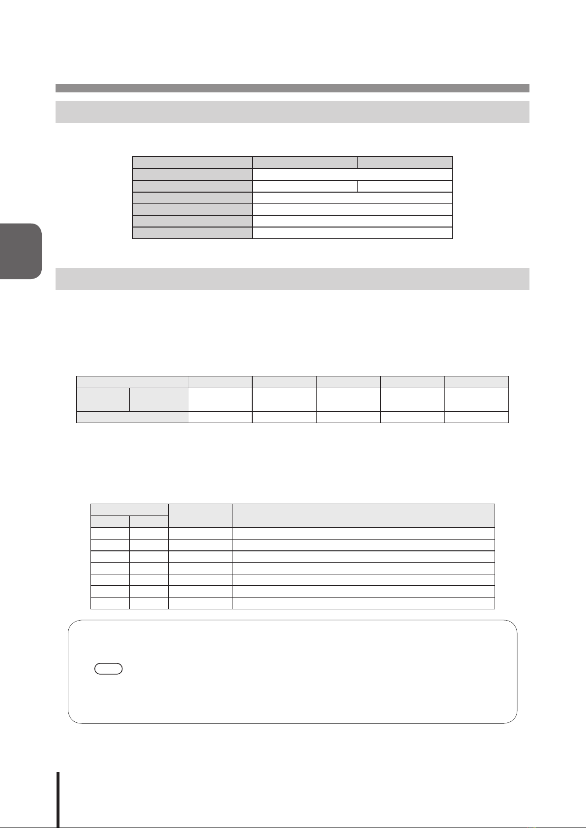
3.1. Communication Set Up
When sending a command to this product, set the communication port as shown below depending on the
operation mode.
Normal Operation Mode PHU Compatible Mode
CommunicationSpecication RS-232C Compliant
Baud Rate 9600bps 19200bps
Data Length 8 bit
Stop Bit 1 bit
Parity None
Flow Control None
3.2. Normal Operation Mode
Normal Operation Mode can control the Signal Tower and buzzer by sending ASCII data to this product in the
following format.
3.2.1. Frame Format
Below,thetransmitdataformatisexplained.BecausetheIdenticationNumber(hereafter,referredtoas“ID”)is
recorded inside this product, the ID will not change, even if the power is turned off.
Header ID * Command Data End Code
Send Data ASCII Code
[HEXCode]
@
[40H]
??
[3FH3FH]
Refer to the
command list By command !
[21H]
Byte Count 1Byte 2Byte 1Byte 0~6Byte 1Byte
* ID (default setting= “??”) set up for this product is as follows.
Refer to “3.2.2.3. <Set ID for this product>” on how to change the ID. Normally using “??” allows execution of
commands irrespective of the main unit ID.
3.2.1.1. <Comand List>
The list of commands and functions which can be used is shown in the table below.
Command Number of
Data Bytes Function
ASCII Hex
1[31H] 2 Bytes TurnsonaspeciedSignalTowerlightandsoundsthebuzzer
0[30H] 2 Bytes TurnsoffaspeciedSignalTowerlightandstopsthebuzzer
?[3FH] 2 Bytes Changes the ID.
S[53H] 6 Bytes Controls the Signal Tower and buzzer operation.
G[47H] 0 Bytes Acquires the Signal Tower and buzzer conditions
C[43H] 0 Bytes Switches off the Signal Tower lights and buzzer.
M[4DH] 0 Bytes Acquires information from the Signal Tower
• The command is compatible with PHE-3FB2.
• Commands “1” and “0” are compatible with PHE-3FBE1.
• Since the “S” command can control Flashing Pattern 2, as well as Buzzer Patterns 3 and 4,
it is recommended to use the “S” command for controlling those operations for this product.
When using the “S” command, do not use the “1” or “0” commands.
• AftersendingacontrolcommandtotheMainUnitasperit’sspecications,ifthecontrol
commands are sent without waiting for the reply data from the Main Unit, it will not operate
normally (Which is how it is supposed to operate when a NAK reply is not received).
MEMO
3

15
3.2.2. Command Explanation
The following are examples on how to send each of the commands from the command list table.
3.2.2.1. <TurnonspeciedSignalTowerlightandsoundbuzzer>
SendingASCIIdatainthefollowingformwillcontrolthespeciedSignalTowerlighttoturnonandsoundthe
buzzer.Thebitinthedatasectionisspeciedas“0”,ofwhichtheSignalTowerandbuzzerwillmaintaintheir
condition,andthebitinthedatasectionspeciedas“1”willturnofftheSignalTowerlightsandsoundthebuzzer.
[TransmissionExample]
Inthisexample,theSignalTowerredshallash,amberwilllightup,andbuzzer
pattern 2 shall sound.
• Send Data
Header ID Command Data End code
@
[40H]
?
[3FH]
?
[3FH]
1
[30H]
3
[33H]
2
[32H]
!
[21H]
• Reply Data
Normal Response
Data
ACK
[06H]
Response Error
Data
NAK
[15H]
The following are conditions in which will get a NAK reply, and the error contents are as follows.
Transmission Condition Error Contents
Command Error Whencommandsotherthanacommandfromthelistarespecied
Data error Whenthedataoutsideof0[30H]-?[3FH],isspecied
Data size error When the number of bytes in the send data is different
Timeout When the reply interval for every byte exceeds 5 seconds after receiving a header
*Do not transmit the following command, before this product transmits reply data. It may not operate
normally.
MEMO
• If Lighting and Flashing are used simultaneously by the same unit, Lighting will take priority.
• If Buzzer pattern 1 and Buzzer pattern 2 are used simultaneously, Buzzer pattern 1 will take
priority.
3
15 14 13 12 11 10 9 8 7 6 5 4 3 2 1 0
0 0 1 1 0 0 1 1 0 0 1 1 0 0 1 0
Red Unit Lighting
Amber Unit Lighting
Green Unit Lighting
Buzzer Pattern 1
Buzzer Pattern 2
Red Unit Lighting
Amber Unit Lighting
Green Unit Lighting

16
3.2.2.2. <TurnoffspeciedSignalTowerlightandstopbuzzersound>
SendingASCIIdatainthefollowingformwillcontrolthespeciedSignalTowerlighttoturnoffandstopthebuzzer.
Thebitinthedatasectionisspeciedas“0”,ofwhichtheSignalTowerandbuzzerwillmaintaintheircondition,
andthebitinthedatasectionspeciedas“1”willturnofftheSignalTowerlightsandstopthebuzzer.
[TransmissionExample]
Inthisexample,theSignalTowerredashingandamberlightingshallbeturned
off, and buzzer pattern 2 shall stop.
• Send Data
Header ID Command Data End code
@
[40H]
?
[3FH]
?
[3FH]
0
[30H]
5
[35H]
1
[31H]
!
[21H]
• Reply Data
Normal Response
Data
ACK
[06H]
Response Error
Data
NAK
[15H]
The following are conditions in which will get a NAK reply, and the error contents are as follows.
Transmission Condition Error Contents
Command Error Whencommandsotherthanacommandfromthelistarespecied
Data error Whenthedataoutsideof0[30H]-?[3FH],isspecied
Data size error When the number of bytes in the send data is different
Timeout When the reply interval for every byte exceeds 5 seconds after receiving a header
*Do not transmit the following command, before this product transmits reply data. It may not operate
normally.
3
15 14 13 12 11 10 9 8 7 6 5 4 3 2 1 0
0 0 1 1 0 1 0 1 0 0 1 1 0 0 0 1
Red Unit Lighting
Amber Unit Lighting
Green Unit Lighting
Buzzer Pattern 1
Buzzer Pattern 2
Red Unit Lighting
Amber Unit Lighting
Green Unit Lighting

17
3.2.2.3. <Set ID for this product>
Sending ASCII data in the following form will change the ID of this product. Two ASCII bytes are designated in the
datasectiontochangetoanewID.Thecongurationrangeforeachbyteofdatainthedatasectioncansetup
from0[30H]to?[3FH].
[TransmissionExample]
In this example, theIDsetat56[35H36H]shallbechangedto21[32H31H].
• Send Data
Header ID Command Data End Code
@
[40H]
5
[35H]
6
[36H]
?
[3FH]
2
[32H]
1
[31H]
!
[21H]
• Reply Data
Normal Response
Data
ACK
[06H]
Response Error
Data
NAK
[15H]
The following are conditions in which will get a NAK reply, and the error contents are as follows.
Transmission Condition Error Contents
Command Error Whencommandsotherthanacommandfromthelistarespecied
Data error Whenthedataoutsideof0[30H]-?[3FH],isspecied
Data size error When the number of bytes in the send data is different
Timeout When the reply interval for every byte exceeds 5 seconds after receiving a header
*Do not transmit the following command, before this product transmits reply data. It may not operate
normally.
3

18
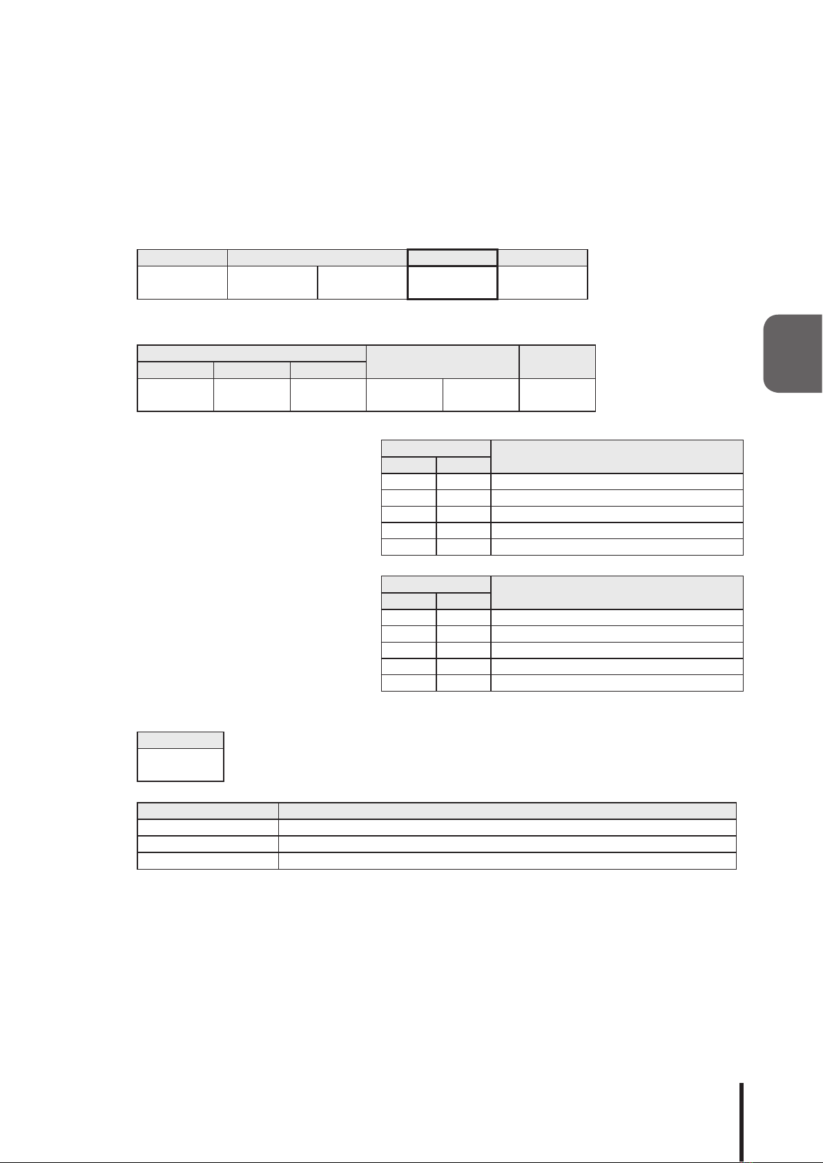
3.2.2.4. <Control Signal Tower and buzzer operation>
Sending ASCII data in the following form will transmit data to control the Signal Tower and buzzer.
[TransmissionExample]
In this example,theredisturnedon,ambermaintainsit’sconditionandgreenisturned
offonthespeciedSignalTower,andthebuzzersoundsPattern4.
• Send Data
Header ID
Command
Data End
Code
Signal Tower *1 Unused *2
Buzzer *3
Red Amber Green
@
[40H]
?
[3FH]
?
[3FH]
S
[53H]
1
[31H]
9
[39H]
0
[30H] --4
[34H]
!
[21H]
*1ListofspecieddataforSignalTower
Command Function
ASCII Hex
0[30H] Turns Signal Tower Lighting off
1[31H] Turns Signal Tower Lighting on
2[32H] Turns on Signal Tower Flashing Pattern 1
3[33H] Turns on Signal Tower Flashing Pattern 2
9[39H] No Change in Conditon
*2Thisvalueisundened.
*3Listofspecieddataforbuzzer
Command Function
ASCII Hex
0[30H] Mutes the Buzzer
1[31H] Turns on Buzzer Pattern 1
2[32H] Turns on Buzzer Pattern 2
3[33H] Turns on Buzzer Pattern 3
4[34H] Turns on Buzzer Pattern 4
9[39H] No Change in Conditon
• Reply Data
Normal Response
Data
ACK
[06H]
Response Error
Data
NAK
[15H]
The following are conditions in which will get a NAK reply, and the error contents are as follows.
Transmission Condition Error Contents
Command Error Whencommandsotherthanacommandfromthelistarespecied
Data error Whenthedataoutsideof0[30H]-?[3FH],isspecied
Data size error When the number of bytes in the send data is different
Timeout When the reply interval for every byte exceeds 5 seconds after receiving a header
*Do not transmit the following command, before this product transmits reply data. It may not operate
normally.
3
19
3.2.2.5. <Acquire Signal Tower and buzzer conditions>
When ASCII data is transmitted in the following format, the reply data will return with a 6 byte ASCII value to
indicate the Signal Tower and buzzer status.
[TransmissionExample]
In this example, the acquisitioned data obtained indicate the condition in which red is
“off”,amberis“on”andgreenisashingpattern2onthesignaltower,withthebuzzer
sounding pattern 3.
• Send Data
Header ID Command End Code
@
[40H]
?
[3FH]
?
[3FH]
G
[47H]
!
[21H]
• Reply Data
Normal Response
Signal Tower *1 Unused Buzzer *2
Red Amber Green
0
[30H]
1
[31H]
3
[33H]
0
[30H]
0
[30H]
3
[33H]
*1 List of reply data for Signal Tower
Command Function
ASCII Hex
0[30H] Signal Tower Lighting is turned off
1[31H] Signal Tower Lighting is turned on
2[32H] Signal Tower Flashing Pattern 1 is turned on
3[33H] Signal Tower Flashing Pattern 2 is turned on
9[39H] No Change in Conditon
*2 List of reply data for buzzer
Command Function
ASCII Hex
0[30H] Buzzer is muted
1[31H] Buzzer Pattern 1 is turned on
2[32H] Buzzer Pattern 2 is turned on
3[33H] Buzzer Pattern 3 is turned on
4[34H] Buzzer Pattern 4 is turned on
Response Error
Data
NAK
[15H]
The following are conditions in which will get a NAK reply, and the error contents are as follows.
Transmission Condition Error Contents
Command Error Whencommandsotherthanacommandfromthelistarespecied
Data size error When the number of bytes in the send data is different
Timeout When the reply interval for every byte exceeds 5 seconds after receiving a header
*Do not transmit the following command, before this product transmits reply data. It may not operate
normally.
3

20
3.2.2.6. <Turn off Signal Tower light and stop the buzzer>
Sending ASCII data in the following form will control the Signal Tower light to turn off and stop the buzzer.
[TransmissionExample]
In this example, the Signal Tower lights are turned off and the buzzer is stopped.
• Send Data
Header ID Command End Code
@
[40H]
?
[3FH]
?
[3FH]
C
[43H]
!
[21H]
• Reply Data
Normal Response
Data
ACK
[06H]
Response Error
Data
NAK
[15H]
The following are conditions in which will get a NAK reply, and the error contents are as follows.
Transmission Condition Error Contents
Command Error Whencommandsotherthanacommandfromthelistarespecied
Data size error When the number of bytes in the send data is different
Timeout When the reply interval for every byte exceeds 5 seconds after receiving a header
*Do not transmit the following command, before this product transmits reply data. It may not operate
normally.
3
This manual suits for next models
2
Table of contents
Other Patlite Media Converter manuals

Popular Media Converter manuals by other brands


H&B
H&B TX-100 Installation and instruction manual

Bolin Technology
Bolin Technology D Series user manual

IFM Electronic
IFM Electronic Efector 400 RN30 Series Device manual

GRASS VALLEY
GRASS VALLEY KUDOSPRO ULC2000 user manual

Linear Technology
Linear Technology DC1523A Demo Manual

Lika
Lika ROTAPULS I28 Series quick start guide

Weidmuller
Weidmuller IE-MC-VL Series Hardware installation guide

Optical Systems Design
Optical Systems Design OSD2139 Series Operator's manual

Tema Telecomunicazioni
Tema Telecomunicazioni AD615/S product manual

KTI Networks
KTI Networks KGC-352 Series installation guide

Gira
Gira 0588 Series operating instructions

Lika
Lika SFA-5000-FD user guide