Patlite PHC-D08 User manual

T95100238 C
PHC-D08
User's Manual
Interface Converter
Model
PHC-D08
PHC-D08N

2
Table of Contents
Introduction 4
Notice 4
FCC Compliance 4
Product Checklist 4
For safe application, observe the following: 5
Cautionary Notes 5
1. Part Names and Dimensions 6
1.1.ModelNumberConguration 6
1.2. Part Names 6
1.2.1. Main Unit 6
1.2.2. AC Adaptor 6
1.3. Outer Dimensional Drawing 7
1.3.1. Main Unit 7
1.3.2. AC Adaptor 7
2. Product Installation 8
2.1. Rubber Feet Installation 8
2.2. Terminal Wiring 9
2.2.1. Output Terminal Wiring 9
2.2.2. Output Power Supply Terminal Wiring 10
2.3. RS-232C Port Wiring 11
2.4. USB Port Wiring 12
2.5. "Set" Switch 13
2.6. "Clear" Switch 13
2.7. Power Activation 14
2.8. Wiring Example 15
3. CommunicationSpecications 16
3.1. Communication Setting 16
3.2. Frame Format 16
3.2.1. <Comand List> 16
3.3. Command Explanation 17
3.3.1. <TurnONSpeciedOutputTerminal> 17
3.3.2. <TurnOFFSpeciedOutputTerminal> 18
3.3.3. <Set ID for this product> 19
3.3.4. <ControlSpeciedOutputTerminal> 20
3.3.5. <Obtain Output Terminal Condition> 21
3.3.6. <Turn all Output Terminals OFF> 22
3.3.7. <Obtain Information on this product> 23

3
4. Maintenance 24
4.1. Setup Test Mode 24
5. Specications 25
5.1.GeneralSpecications 25
5.2.FunctionalSpecications 26
6. Maintenance and Inspection 27
7. Replacement Parts 28
8. Troubleshooting 29

Intro
4
Introduction
Thank you for purchasing the PATLITE “PHC-D08” (henceforth, written as “this product”) Interface Converter.
Before installation and use, read this manual (henceforth, referred to as “this book”) and follow the cautions and
guidelines presented. In addition, store this manual for future reference when performing maintenance, repairs or
inspections. When performing maintenance and repairs, etc., be sure to reread this book.
After reading this book, if there are any questions concerning this product, feel free to contact your PATLITE Sales
Representative indicated at the end of this book.
Notice
►The copyrights of this book is owned by the PATLITE Company, Inc. (henceforth referred to as “our company”).
Any reproduction, duplication, alteration, or extracting portions of this book, etc., without written permission
from our company is forbidden.
► Specications,thedesign,andothercontentswritteninthisbookmaybechangedforimprovementswithout
prior notice and may result in differences from the actual product purchased.
►This product meets severe quality control and inspection requirements prior to shipment, but if some failure or
defect is found, please contact the place of purchase, or your PATLITE Sales Representative (indicated on the
last page) to solve the issue.
► Thisproduct(softwareisincluded)isfortheuseofgeneralofcework,homeandforpersonaluse,ithasbeen
developed, designed and manufactured for general applications, such as for industry, and it is not designed
for applications which demands high safety requirements, such as medical application equipment or systems
used in connection directly, or indirectly, with human life. Please understand prior to use that no responsibility
is taken at our company for damages or other disadvantages, due to customers using this product beyond the
scope of its general application, or from any claims from third parties. When using this product for applications
in which equipment of higher reliability than the general application demands, such as a computer system, etc.,
use suitable safety design countermeasures against system failure, etc.
►Please understand that our company does not take any responsibility for damage and other disadvantages
this product (software is included) has caused due to the customer using this product, or any claims from third
parties.
►This product (Body only) conforms to EN standards and shows the CE Markings.
►The AC Adaptor included does not conform to the EN standards, therefore does not show CE Markings.
FCC Compliance
This equipment has been tested and found to comply with the limits for a Class A digital device, pursuant to Part 15
of the FCC Rules. These limits are designed to provide reasonable protection against harmful interference when the
equipment is operated in a commercial environment. This equipment generates, uses and can radiate radio frequency
energy and, if not installed and used in accordance with the instruction manual, may cause harmful interference to radio
communications. Operation of this equipment in a residential area is likely to cause harmful interference in which case
the user will be required to correct the interference at his own expense.
Product Checklist
The following items are contained with this product.
■Main Unit (1 Body)
■Installation Manual (1 Sheet)
■Product Assurance Provisions (1 Sheet)
■Rubber Feet (4 Pieces)
■AC Adaptor (1 Unit- for PHC-D08 only)
Intro
5
For safe application, observe the following:
Thefollowingsymbolsclassifesthefollowingintodifferentcatagoriesandexplainsthelevelofharminictedifthe
cautions are disregarded.
Warning Indicates an imminently dangerous condition: failure to follow the instructions may lead to
death or serious injury.
Caution Indicates a potentially dangerous condition: failure to follow the instructions may lead to injury
or damage to property.
Prohibited This symbol indicates “Prohibited”, which should not be carried out by all means.
Enforced This symbol indicates “Enforced”, which should be observed and carried out by all means.
MEMO Notice regarding supplementary information or convenient explanation is indicated.
Cautionary Notes
Prior to installation, read all notes and use this product correctly.
Warning
Prohibited
• Donotdisassembleoraltertheproduct.Failuretocomplymayresultinre,electricshock,orfailure.
• Do not touch the electric socket with wet hands. Failure to comply will result in electric shock.
• The power supply rating for the AC Adaptor is 100-240VAC. Do not allow the voltage to exceed the
speciedvoltagetolerance.Failuretocomplywillresultininternalcircuitrydamageorre.
• After mounting this product on the machine, do not remove the cover, or hook anything onto the
product, or use the product as a step when climbing onto the machinery. Failure to comply may result
in falling off the machinery, or product damage may occur.
• Do not insert or pull out the DC plug while power for the AC Adaptor is on. It may cause electrical
shock, failure, etc.
Enforced
• When plugging the AC Adaptor into the power receptacle, be sure to check there is no dust
accumulation on the plug, and insert into the power receptacle completely. By allowing dust to adhere
totheACAdaptor,itcanbetheresultofreorfailurefromshort-circuiting.
• Since dust can accumulate after a long time, and with moisture, can cause the dust to become
conductive, in order to prevent the phenomenon of ignition from dust accumulation, it is best to
periodically wipe the AC Adaptor and power receptacle with a damp cloth. By allowing dust to adhere
totheACAdaptor,itcanbetheresultofreorfailurefromshort-circuiting.
• Perform wiring work only after turning off power of the equipment to be connected and this product.
There is a risk of internal circuit damage due to short-circuit or electrical shock.
• When an unusual odor, sound or smoke comes out of the product, immediately disconnect the power,
then contact your nearest PATLITE Sales Representative.
Caution
Enforced
• Please place this product on a level surface, such as a desk etc.
• When installing it in high places, such as on top of a shelf, use the rubber feet included on the bottom
of the body to prevent it from sliding around and falling.
Prohibited
• Donotexposeittohightemperatures,suchasnearareanddonotuseitinhumidplaces.Moreover,
do not use this product in locations where corrosive or combustible gas is present.
• If foreign substances, such as water, chemicals; or metals, such as copper, low carbon steel wire, fall
into this product, do not use it. Possible cause of failure may occur.
• Do not disassemble or attempt to repair this product by any means. Failure to comply will result in
equipmentdamageorre.
• Do not bend the power supply cables or signal wires recklessly. Disconnection will result in this product
breaking down.
• Do not install or run wiring near, or where equipment (such as solenoids, etc.) generate strong electric
ormagneticelds,ornearanypowerlines.Failuretocomplymayresultinmalfunctionduetoinductive
noise.
• Do not place any part of this product (Body, AC Adaptor, Rubber Feet) where infants can reach it. If it is
swallowed accidentally, it could be detrimental. If it is suspected of being swallowed, please consult an
emergency medical center immediately.
6
1
1. Part Names and Dimensions
1.1. Model Number Conguration
PHC-D08
1.2. Part Names
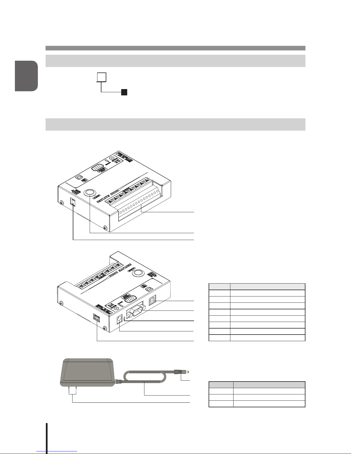
1.2.1. Main Unit
Number Name
1Output Terminal Buss
2 “Clear” Switch
3 “Set” Switch
4 USB Port (Type-B)
5 RS-232C Port (D-sub 9 pin male)
6 Power Supply LED
7 DC Jack
8 Power Supply Output Terminal
1.2.2. AC Adaptor
Number Name
1 DC Plug
2 Power Supply Cable
3 Outlet Plug
: AC Adaptor
Blank: AC Adaptor included
N: AC Adaptor not included
①
②
③
④
⑤
⑥
⑧
⑦
①
②
③

7
1
1.3. Outer Dimensional Drawing
1.3.1. Main Unit
1.3.2. AC Adaptor
49
37
1650
76
(Unit: mm)
117
28
100
(Rubber feet
not included)
(Unit: mm)

2
8
2. Product Installation
Caution
Prohibited
• This product is designed for indoor use. Use this product in a location where it is not exposed to
rain and water. Exposure to rain and water may result in failure and electric shock.
• Install this product where the surface is stable and level. If this product is installed in an unstable
location or on an incline, the product may fall, resulting in damage.
• When installing this product, avoid installating it in the following places:
■Whereit’sexposedtodirectsunlight
■Wherehightemperaturesarepresent,suchasnearre,orinahumidplace
■Wheredrastictemperatureandhumidiychangesarepresent
■Whereit’sexposedtoanenvironmentwithpoorventillation
■Whereit’sexposedtovibrationsexceedingthespecications
■Whereit’sexposedtocorrosivegas
■Whereit’sexposedtoasaltyairenvironment
■Whereit’sexposedtodust,ironpowder,etc.
■Whereit’sexposedtohighconcentrationsofchemicalsoroilmist
■Whereit’sexposedtorain,orothertypesofwetenvironments
2.1. Rubber Feet Installation
Prior to the installation of this product, locate a stable and level location, then attach the enclosed rubber feet (four
pieces) to the bottom surface of this product.
Peel off the release paper
and paste to four corners.
Rubber Feet (4 pieces)
Main Unit

9
2
2.2. Terminal Wiring
Warning
Enforced
• Perform wiring work only after turning off power of the equipment to be connected and this product.
There is a risk of internal circuit damage due to short-circuit or electrical shock.
• Screw-less terminal blocks are used in this product; be sure to use wires which characteristics such
as wire type, wire diameter, and strip length are described in this manual. Failure to do so may
cause contact failure, heat generation and loose wires, since the wire is not securely connected.
• Be sure to insert the entire conductive part of the wire. If a stranded wire is sticking out from the wire
inlet,orabarewiretouchesthecase,itmaycausefailureandpossibleretothemainunitbyshort
circuiting.
• Payattentiontoavoidwrongconnections,apossibilityofreordamagemayresult.
Caution
Enforced
• Do not push the actuator part of the terminal block too hard. Doing so may result in the damage or
failure of the terminal block and main unit.
• After completing the wiring, make sure that there are no loose, disconnected or bare lead wires.
2.2.1. Output Terminal Wiring
Wire the output terminal according to the following steps.
[Wiring Method]
1. Useaminusdrivertopushinthetabofthecontrolunit’sterminalbussslot.
2. Insert a signal line lead wire into the slot. (Keep pushing the tab while inserting)
3. Release the minus driver to lock the lead wire in place.
Applicable Wires
Solid Wire: Diameter 0.4 mm to 1.2 mm (AWG26 to AWG18)
Stranded Wire: Diameter 0.2 mm2to 0.75 mm2(AWG24 to AWG20)
* Single wire diameter shall be 0.18 mm or more for stranded wire.
Wire Coating
Strip Length 9mm
Suitable Actuator Tool Widthofatheadscrewdriverbit:1.5to2.5mm
Thickness of bit: 0.5 to 0.7 mm
Caution
• Do not connect AC power to the Output Terminal Block. Failure to comply may result in a
short-circuitandre.
• UsetheOutputTerminalBlockwithinthecontact’sratedcapacity.Failuretocomplymay
resultinmalfunctionandpossiblere.
• Iftheinrushloadcurrentexceedsthecontact’sratedcapacity,scorchingand
welding of
the contacts may occur. Therefore, do not apply such a load.
Rated Contact Capacity DC30V 3A
②
①
③

2
10
2.2.2. Power Supply Output Terminal Wiring
The Power Supply Output Terminal can be used to control an external load when an AC Adaptor is used. When
using the Power Supply Output Terminal, wire in accordance to the directions indicated below.
[Wiring Method]
1. Useaminusdrivertopushinthetabofthecontrolunit’sterminalbussslot.
2. Insert a lead wire into the slot. (Keep pushing the tab while inserting)
3. Release the minus driver to lock the lead wire in place.
Applicable Wires
Single Wire: Diameter 0.4 mm to 1.2 mm (AWG26 to AWG18)
Stranded Wire: Diameter 0.2 mm2to 1.25 mm2(AWG24 to AWG16)
* Single wire diameter shall be 0.18 mm or more for stranded wire.
Wire Coating
Strip Length 9mm
Suitable Actuator Tool Widthofatheadscrewdriverbit:1.5to2.5mm
Thickness of bit: 0.5 to 0.7 mm
Caution
• Do not connect any voltage to the Power Supply Output Terminal. Failure to comply will
resultindamagetotheproductandpossiblere.
• Maintain the consumption current of the equipment linked to the Power Supply Output
Terminal so as to not exceed the ratings indicated below. Do not connect any equipment
which consumes more current than the rated capacity. Failure to comply may result in
malfunction or damage.
Power Output Voltage DC24V
Power Output Current 500mA or less
MEMO • The Power Supply Output Terminal cannot be used without an AC Adaptor used. Be sure to
connect an AC Adaptor when using the Power Supply Output Terminal.
①
③
②
+-
11
2
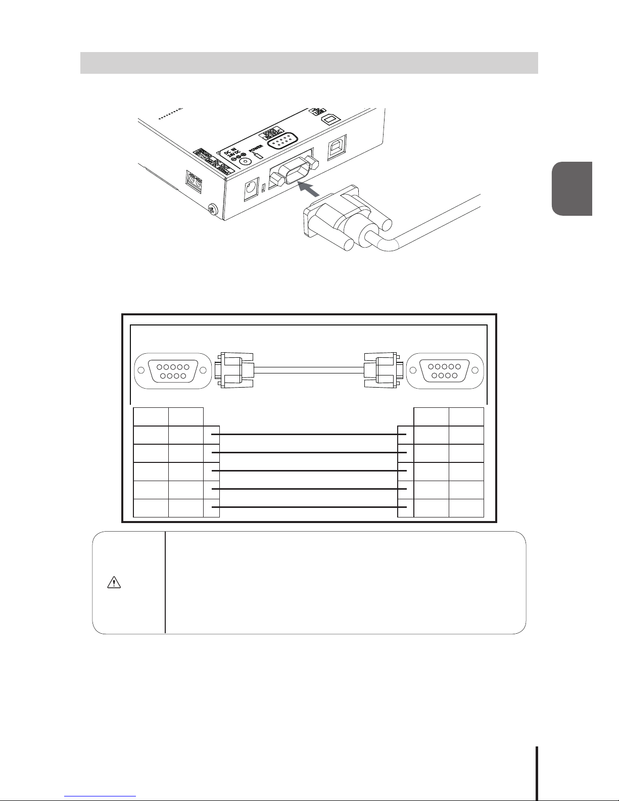
2.3. RS-232C Port Wiring
By connecting to the RS-232C (male) of this product and the RS-232C port of a PC with a D-sub 9 pin female-to-
female type cable with straight wire connection, this product can be controlled via RS-232C transmission.
*The RS-232C cable is not included. Please purchase it separately.
Connect the cables with the connection pin numbers listed below. The pin numbers that are not shown will not
affect the operation of this product.
Caution
• Use a straight RS-232C cable when connecting to the connection devices (PC). This
product may malfunction and cause failure to the Main Unit and other connected devices if
they are used together with other devices.
• Do not bundle the RS-232C cable with power supply cords when being used. Failure to
comply may result in malfunction from power line noise.
• Do not connect the RS-232C and USB cables simultaneously. Failure to comply may
result in malfunction.
• Do not pull out or insert the RS-232C cable while the power supply is turned on.
PHC-D08 Control Device
(PC)
2
3
5
7
8
RXD
TXD
GND
RTS
CTS
RXD
TXD
GND
RTS
CTS
2
3
5
7
8
Pin No. Pin No. SignalSignal
D-sub 9 pin female
inch thread
D-sub 9 pin female
inch thread
1
6 9
51
6 9
5
Signal Pin No. Pin No. Signal
TXD 2 2 RXD
RXD 3 3 TXD
GND 5 5 GND
CTS 7 7 RTS
RTS 8 8 CTS
2
12
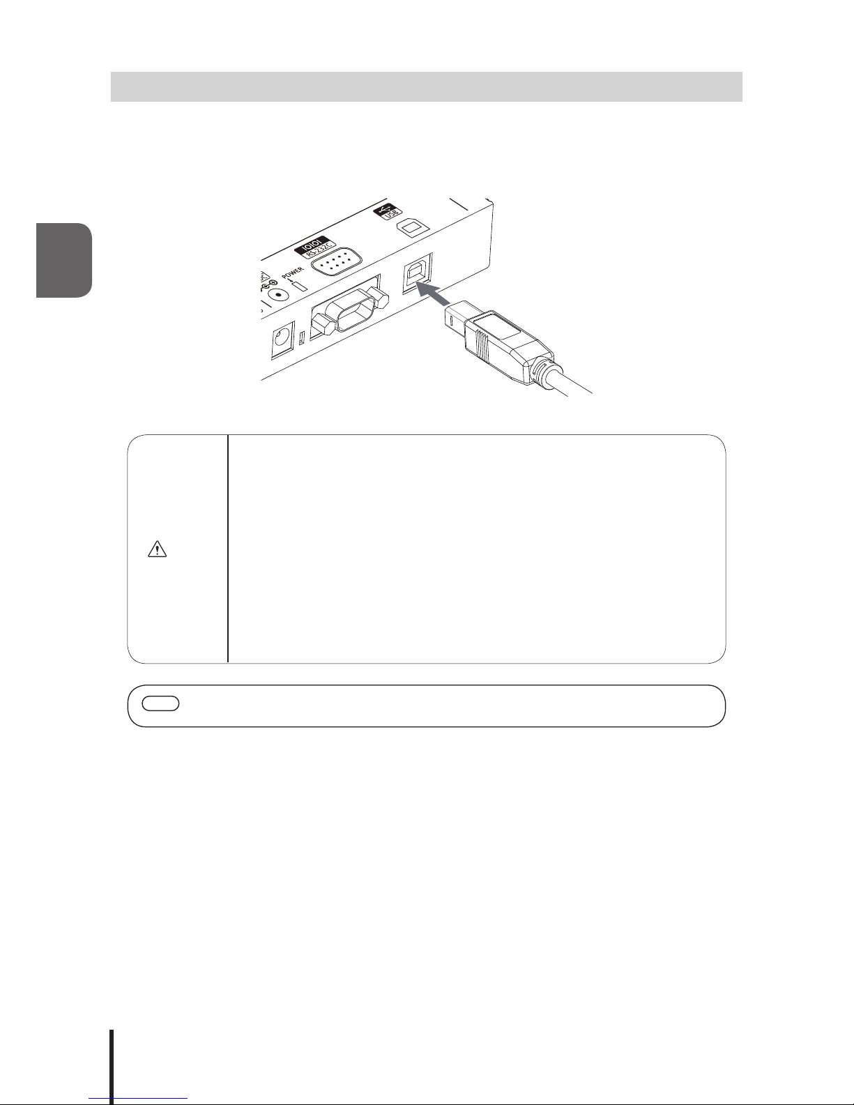
2.4. USB Port Wiring
This product can be controlled via USB transmission by connecting a USB (Type B) cable from the main unit to the USB
port of a PC. Since this product can operate on USB Bus Power, it can be used without an AC Adaptor. However, this
product requires installation of a specialized driver for the PC before being connected to a PC via the USB. Go to our
PATLITE homepage (http://www.patlite.com) to download the installer.
*The USB cable is not included. Please purchase it separately.
Caution
• UseastraightUSBcablewhenconnectingtotheconnectiondevice’sport(PC).
This product may malfunction and cause failure to the Main Unit and other connected
devices if they are used together with other devices.
• Do not bundle the USB cable with power supply cords when being used. Failure to comply
may result in malfunction from induced noise.
• Do not connect the USB and RS-232C cables simultaneously. Failure to comply may
result in malfunction.
• Do not insert or pull out the USB cable while the power supply is turned on.
• Depending on the feeding power capability of the Main Unit or the USB port of the personal
computer, operation may become unstable. Use an AC Adaptor if this condition occurs.
• Use this product by connecting the USB cable directly, without the use of a USB hub.
Failure to comply may cause unstable operation.
• It is recommended to use a USB cable with the length of 2m or less. Cables longer than 2m
may cause unstable operation due to induced noise from the surrounding environment.
MEMO • When installing exclusive drivers for compatible Operating Systems, etc., refer to the
instructions attached to the drivers.
13
2
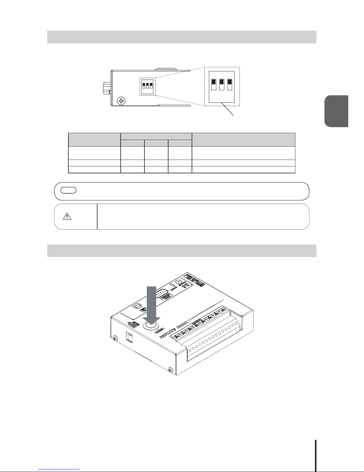
2.5. "Set" Switch
The operation mode of this product can be changed by changing the set switch located on the side of this product,
before power activation.
The operation modes available are as follows:
Operation Mode Set Switch Function
123
Normal Operation OFF OFF OFF Operation by commands of
“3.2. Frame Format”
Setup Test OFF ON OFF Operation by “4. Setup Test Mode”
Firmware Update ON OFF OFF Updatingrmwareofthisproduct
MEMO • Forinstructionsonupdatingthermware,downloadtheinstructionsfromPatlite’shomepage
and check the manual.
Caution
• When in the “Setup Test” and “Firmware Update” Modes, the commands for the “Normal
Operation Mode” will not work. Therefore, put the “Set” Switches in the “Normal Operation
Mode” and reactivate the power before sending commands.
2.6. "Clear" Switch
Pressing the “Clear” switch will turn off the output terminals.
1 2
ON↓
3
Set Switch
1 2
ON↓
3

2
14
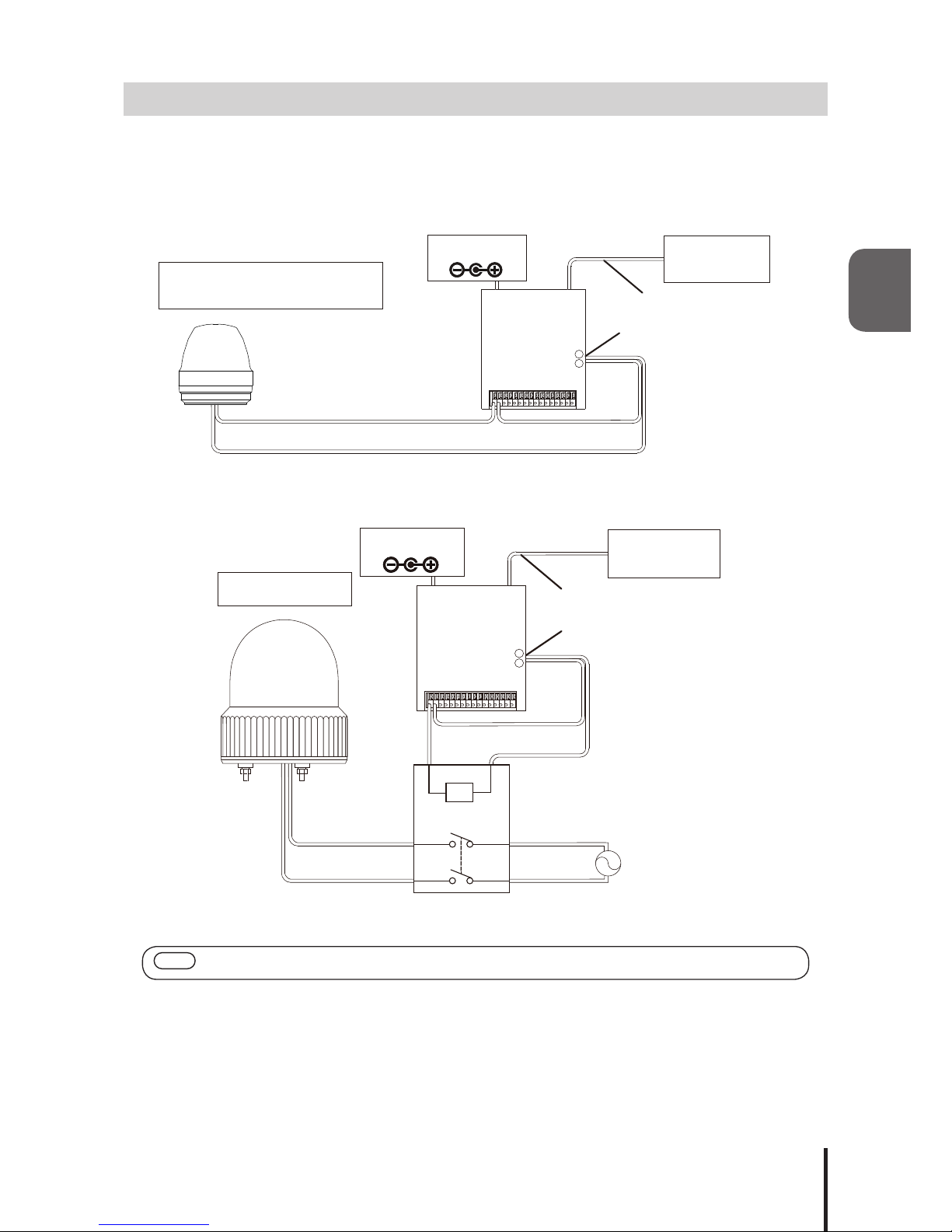
2.7. Power Activation
Two options for power activation are available for this product, using the AC Adaptor or USB Bus Power. Select
among the power sources below that match your environment and turn on the power.
1. When using an AC Adaptor:
Insert DC plug into the main body of this product, and insert the AC adapter into an outlet. When power is
switched on, the Power Supply LED will light up.
2. When using USB Bus Power
Insert the USB cable into the main body of this product and insert the top of the USB cable into the PC which
has compatible bus power. When power is switched on, the Power Supply LED will light up.
Warning
• Do not insert or pull out the DC Plug while power for the AC Adaptor is on. Failure to
comply may result in electrical shock or product malfunction, etc.
• When plugging the AC Adaptor into the power receptacle, be sure to check there is no
dust accumulation on the plug, and insert it into the power receptacle completely. By
allowing dust to adhere to the AC Adaptor plug or Power Supply Terminal, it may result in
reordamagefromshort-circuiting.
• Do not touch the electric socket with wet hands. Failure to comply will result in electric
shock.
Caution
• Depending on the feeding power capability of the Main Unit or the USB port of the personal
computer, operation may become unstable. Use an AC Adaptor if this condition occurs.
• Use this product by connecting the USB cable directly, without the use of a USB hub.
Failure to comply may cause unstable operation.
• The
Power Supply Output Terminal cannot be used when the USB
Bus Power is used.
Connect an AC Adaptor in order to use the Power Supply Output Terminal.
Power Supply LED
1. AC Adaptor 2. USB Cable
15
2
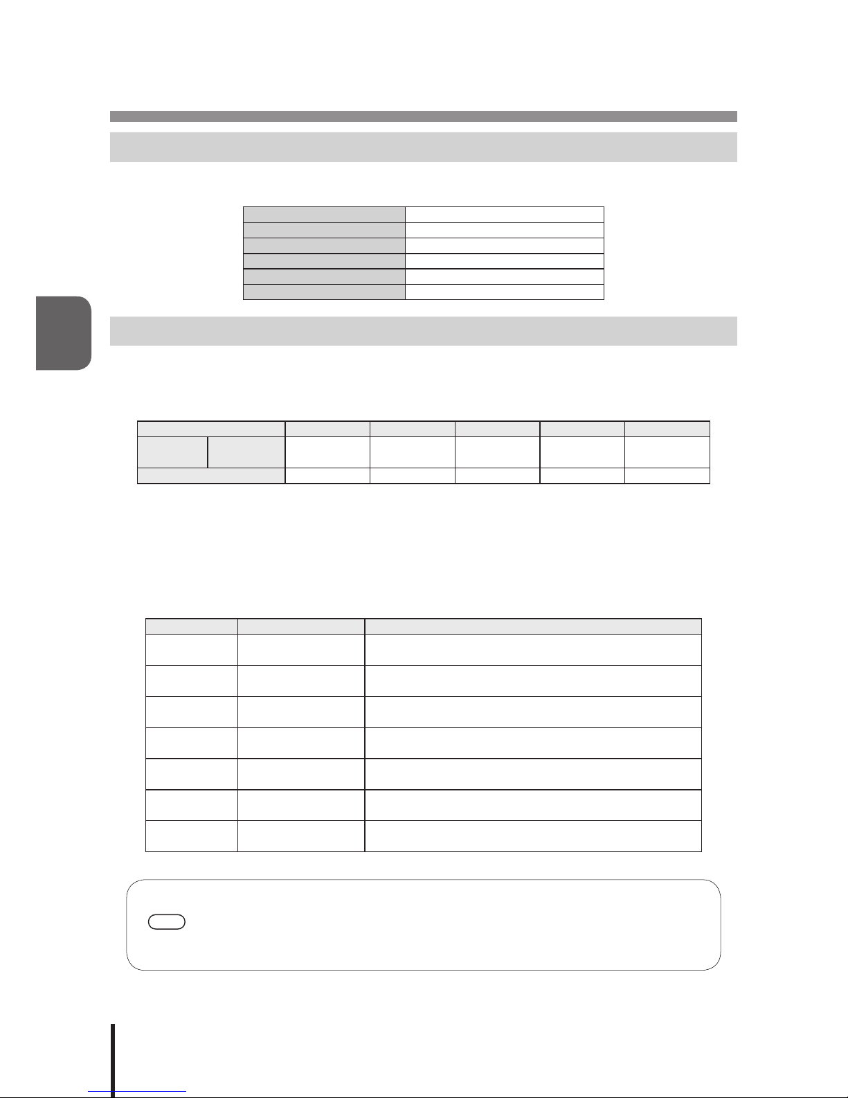
2.8. Wiring Example
The internal contacts are non-voltage relay contacts. Operate the Terminal Buss below a contact capacity of
DC30V at 3A. In addition, since each contact is independent, different voltages can be connected to the product
for each contact. The Power Supply Output Terminal can supply a maximum current of 500mA at DC24 Volts.
2.8.2.1. <DC Load Products>
2.8.2.2. <AC Load Products>
MEMO • Use the AC Adaptor when using the
Power Supply Output Terminal
in the wiring example.
<PHC-D08>
Power Supply Wire (Positive)
Power Supply Wire (Negative)
Signal Light, Signal Tower,
Alarm/ Voice Synthesizer
Power Supply
Output Terminal
USB or RS-232C
Cable
+
-
Control Device
(PC)
AC Adaptor
<PHC-D08>
AC Load Products
Power Supply
Output Terminal
USB or RS-232C Cable
+
-
Control Device
(PC)
AC Adaptor
Relay AC Power Supply
16
3
3. Communication Specications
3.1. Communication Setting
When transmitting a command to this product from a personal computer, be sure to set up the communication
settings as followed.
CommunicationSpecication RS-232C Conformity
Communication Speed 9600bps
Data Length 8 bit
Stop bit 1 bit
Parity None
Flow Control None
3.2. Frame Format
The Output Terminal Buss is controllable by transmitting the data in the following format to this product from a personal
computer.BecausetheIdenticationNumber(hereinafter,referredtoas“ID”)isrecordedinsidethisproduct,theIDwill
not change even if the power is turned off.
Header ID * Command Data End Code
Send Data ASCII Code
[HEX Code]
@
[40H]
??
[3FH 3FH]
Refer to the list
of commands By command !
[21H]
byte count 1Byte 2Byte 1Byte 0~8Byte 1Byte
* ID (default setting= “??”) set for this product is as follows.
When changing the ID number for this product, refer to “3.2.3 Set ID for this Product.”
Since“??”canbeusedtoexecuteacommandirrespectiveoftheproduct’sID,use“??”whenexecuting
commands.
3.2.1. <Comand List>
The list of commands and functions which can be used is shown in the table below.
Command Number of Data bytes Function
1
[31H] 2Byte TohavethespeciedOutputTerminalON
0
[30H] 2Byte TohavethespeciedOutputTerminalOFF
?
[3FH] 2Byte To set the ID of this product
S
[53H] 8Byte TocontrolspeciedOutputTerminalasspeciedconditions
G
[47H] 0Byte To obtain the condition of the Output Terminal
C
[43H] 0Byte To have all Output Terminals OFF
M
[4DH] 0Byte To obtain information on this product
MEMO
• A “1” and “0” Command has compatibility with the PC Output Relay Unit, PHC-100A.
• Since command “S” can control the ON/OFF of the Output Terminals simultaneously, it is
recommended to use the “S” command for controlling those operations for this product.
• AftersendingacontrolcommandtotheMainUnitasperit’sspecications,ifthecontrol
commands are sent without waiting for the reply data from the Main Unit, it will not operate
normally (Which is how it is supposed to operate when a NAK reply is not received).

17
3
3.3. Command Explanation
The following are examples on how to send each of the commands from the command list table.
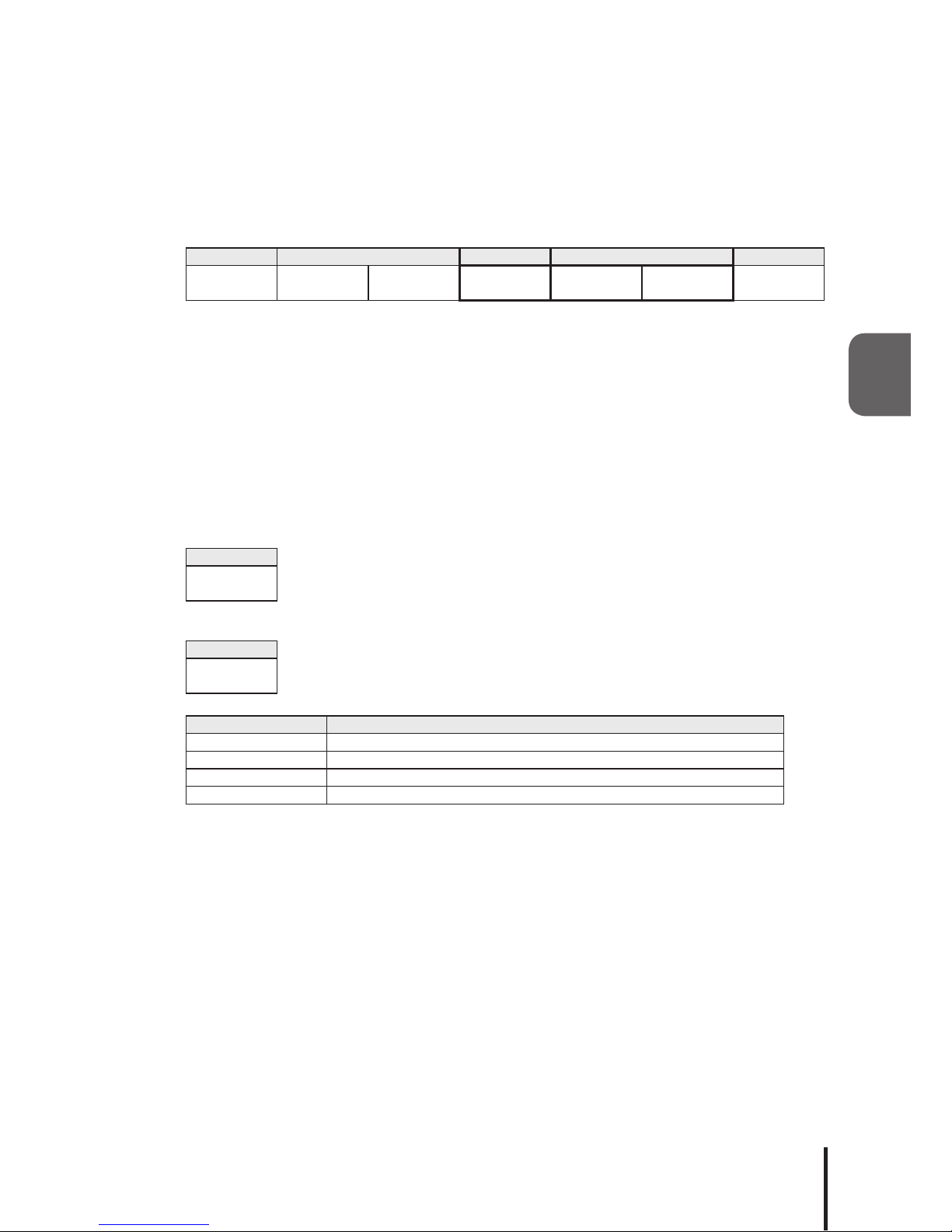
3.3.1. <Turn ON Specied Output Terminals>
SendingdatainthefollowingformatwillcontrolthespeciedOutputTerminaltoturn“ON.”Thebitinthedata
sectionspeciedas0,willmaintainthespeciedOutputTerminal’scondition,andthebitinthedatasection
speciedas1willturnonthespeciedOutputTerminal.
[Transmission Example]
In this example, the Output Terminals 2, 5, and 6 are turned ON.
• Send Data
Header ID Command Data End Code
@
[40H]
?
[3FH]
?
[3FH]
1
[30H]
3
[33H]
2
[32H]
!
[21H]
• Reply Data
Normal Response
Data
ACK
[06H]
Response Error
Data
NAK
[15H]
The following are conditions which will get a NAK reply and the error contents.
Transmission Condition Error Contents
Command error Whenacommandotherthanonthelistofcommandsisspecied
Data error When data, other than 0[30H] - ?[3FH], is used
Data size error When the number of bytes in the send data is different
Timeout Reply interval between data is more than 5 seconds after receipt of header
* Do not transmit the following command, before this product transmits reply data. It may not operate
normally.
15 14 13 12 11 10 9 8 7 6 5 4 3 2 1 0
0 0 1 1 0 0 1 1 0 0 1 1 0 0 1 0
Output Terminal 1
Output Terminal 2
Output Terminal 3
Output Terminal 4
Output Terminal 5
Output Terminal 6
Output Terminal 7
Output Terminal 8

18
3
3.3.2. <Turn OFF Specied Output Terminals>
SendingdatainthefollowingformatwillcontrolthespeciedOutputTerminaltoturn“OFF.”Thebitinthedata
sectionspeciedas0,willmaintainthespeciedOutputTerminal’scondition,andthebitinthedatasection
speciedas1willturnoffthespeciedOutputTerminal.
[Transmission Example]
In this example, the Output Terminals 1, 5, and 7 are turned OFF.
• Send Data
Header ID Command Data End Code
@
[40H]
?
[3FH]
?
[3FH]
0
[30H]
5
[35H]
1
[31H]
!
[21H]
• Reply Data
Normal Response
Data
ACK
[06H]
Response Error
Data
NAK
[15H]
The following are conditions which will get a NAK reply and the error contents.
Transmission Condition Error Contents
Command error Whenacommandotherthanonthelistofcommandsisspecied
Data error When data, other than 0[30H] - ?[3FH], is used
Data size error When the number of bytes in the send data is different
Timeout Reply interval between data is more than 5 seconds after receipt of header
* Do not transmit the following command, before this product transmits reply data. It may not operate
normally.
15 14 13 12 11 10 9 8 7 6 5 4 3 2 1 0
0 0 1 1 0 1 0 1 0 0 1 1 0 0 0 1
Output Terminal 1
Output Terminal 2
Output Terminal 3
Output Terminal 4
Output Terminal 5
Output Terminal 6
Output Terminal 7
Output Terminal 8
19
3
3.3.3. <Set ID for this product>
Sending data in the following form will change the ID of this product. Two ASCII bytes are designated in the data
sectiontochangetoanewID.Thecongurationrangeforeachbyteofdatainthedatasectioncansetupfrom0
[30H] to ? [3FH].
[Transmission Example]
In this example, the ID set at 56 [35H 36H] shall be changed to 21 [32H 31H].
• Send Data
Header ID Command Data End Code
@
[40H]
5
[35H]
6
[36H]
?
[3FH]
2
[32H]
1
[31H]
!
[21H]
• Reply data
Normal response
Data
ACK
[06H]
Response Error
Data
NAK
[15H]
The following are conditions which will get a NAK reply and the error contents.
Transmission Condition Error Contents
Command error Whenacommandotherthanonthelistofcommandsisspecied
Data error When data, other than 0[30H] - ?[3FH], is used
Data size error When the number of bytes in the send data is different
Timeout Reply interval between data is more than 5 seconds after receipt of header
* Do not transmit the following command, before this product transmits reply data. It may not operate
normally.

20
3
3.3.4. <Control Specied Output Terminal>
Sending data in the following format will transmit data to control the output terminal conditions to; “OFF”, “ON”,
and “No Change.”
The ASCII data is divided into 0 [30H] to designate the output terminal as “OFF”, as 1 [31H] to designate it as “ON”,
and 9 [39H] to maintain the status condition as “No Change.”
[Transmission Example]
In this example, Output Terminal 1 is set to ON, Output Terminal 3 set to OFF and all
others are unchanged.
• Send data
Header ID Command Data (Output Terminal Block) End
Code
1 2 3 4 5 6 7 8
@
[40H]
?
[3FH]
?
[3FH]
S
[53H]
1
[31H]
9
[39H]
0
[30H]
9
[39H]
9
[39H]
9
[39H]
9
[39H]
9
[39H]
!
[21H]
• Reply data
Normal response
Data
ACK
[06H]
Response Error
Data
NAK
[15H]
The following are conditions which will get a NAK reply and the error contents.
Transmission Condition Error Contents
Command error Whenacommandotherthanonthelistofcommandsisspecied
Data error When data, other than 0[30H] - ?[3FH], is used
Data size error When the number of bytes in the send data is different
Timeout Reply interval between data is more than 5 seconds after receipt of header
* Do not transmit the following command, before this product transmits reply data. It may not operate
normally.
This manual suits for next models
1
Table of contents
Other Patlite Media Converter manuals


