Patria Ailon Ailonet 100 User manual

MANUAL 21846
AILONET 100 6.6.2002
AILONET USER MANUAL Done
Copyright Patria Ailon Oy 2002. All rights reserved. 1/24
Prepared JTU 6.6.2002
Checked JNU
Approved TSU
AILONET 100 EVALUATION USER MANUAL
Change Record
Revision Date Page affected Description of Change
019.02.2002 All Initial issue
16.6.2002 All Support for new user interface

MANUAL 21846
AILONET 100 6.6.2002
AILONET USER MANUAL Done
Copyright Patria Ailon Oy 2002. All rights reserved. 2/24
This equipment has been tested and found to comply with the limits for a Class B digital device, pursuant to Part 15 of
the FCC Rules. These limits are designed to provide reasonable protection against harmful interference in a residential
installation. This equipment generates, uses and can radiate radio frequency energy and, if not installed and used in
accordance with the instructions, may cause harmful interference to radio communications. However, there is no guar-
antee that interference will not occur in a particular installation. If this equipment does cause harmful interference to ra-
dio or television reception, which can be determined by turning the equipment off and on, the user is encouraged to try to
correct the interference by one or more of the following measures:
–Reorient or relocate the receiving antenna.
–Increase the separation between the equipment and receiver.
–Connect the equipment into an outlet on a circuit different from that to which the receiver is con-
nected.
–Consult the dealer or an experienced radio/TV technician for help.
This device complies with Part 15 of the FCC Rules and with RSS-210 of Industry Canada.
Operation is subject to the following two conditions:
(1) this device my not cause harmful interference, and
(2) this device must accept any interference received, including interference that may cause undesired
operation.
Warning: Changes or modifications made to this equipment not expressly approved by PATRIA AILON may void the
FCC authorization to operate this equipment.
The contents of this document are provided "as is". Except as required by applicable law, no warranties of any kind, ei-
ther express or implied, including, but not limited to, the implied warranties of merchantability and fitness for a particular
purpose, are made in relation to the accuracy, reliability or contents of this document. Patria Ailon reserves the right to
revise this document or withdraw it at any time without prior notice.
FCC Radiation Exposure Statement
The Access Point complies with FCC radiation exposure limits for uncontrolled environment. This equipment must be
installed and operated with a minimum distance of 20 cm between radiator and users body. If not expressly approved the
transmitter must not be co-located or operating in conjunction with any other antenna or transmitter.

MANUAL 21846
AILONET 100 6.6.2002
AILONET USER MANUAL Done
Copyright Patria Ailon Oy 2002. All rights reserved. 3/24
Contents
1. OVERVIEW ...............................................................................................4
1.1 Features .................................................................................................................. 4
1.2 Physical Interfaces................................................................................................... 5
1.2.1 Connectors........................................................................................................ 5
1.2.2 Indicators .......................................................................................................... 5
1.2.3 Switches............................................................................................................ 6
1.3 System Setup .......................................................................................................... 7
1.3.1 First Connection Using Serial Port .................................................................... 7
1.3.2 First Connection Using Bluetooth...................................................................... 7
1.3.3 First Connection Using 802.11b........................................................................ 7
1.3.4 First Connection Using Ethernet ....................................................................... 8
1.3.5 After First Connection Is Established ................................................................ 8
1.3.6 Selecting User Interface Language................................................................... 8
1.3.7 Selecting Internet Interface ............................................................................... 9
1.3.8 Security............................................................................................................. 9
1.4 Supported PC Cards............................................................................................... 11
2. ADMINISTRATION ..................................................................................12
2.1 Shutdown And Restart............................................................................................ 12
2.1.1 Shutdown......................................................................................................... 12
2.1.2 Restart ............................................................................................................. 12
2.2 Plug-ins................................................................................................................... 13
2.2.1 Installing a Plug-in............................................................................................ 13
2.2.2 Removing a Plugin........................................................................................... 13
2.3 Settings................................................................................................................... 14
2.3.1 Time and Date ................................................................................................. 14
2.3.2 System Update ................................................................................................ 14
2.3.3 Internet Interface.............................................................................................. 15
2.3.4 Bluetooth.......................................................................................................... 16
2.3.4.1 Settings ...................................................................................................... 16
2.3.4.2 Security ...................................................................................................... 16
2.3.4.3 Device Discovery ....................................................................................... 17
2.3.5 802.11b............................................................................................................ 18
2.3.6 Ethernet Settings ............................................................................................. 19
2.3.7 Serial Port Settings .......................................................................................... 20
2.3.8 PC-Card Modem Settings ................................................................................ 21
2.3.9 Password ......................................................................................................... 22
2.3.10 Firewall ......................................................................................................... 23
2.3.10.1 Interfaces ................................................................................................. 23
2.3.10.2 Advanced................................................................................................. 23
2.3.10.3 Factory settings ....................................................................................... 24

MANUAL 21846
AILONET 100 6.6.2002
AILONET USER MANUAL Done
Copyright Patria Ailon Oy 2002. All rights reserved. 4/24
1. OVERVIEW
1.1 Features
Processor, Memory and Operating System:
–Processor: Motorola PowerPC, 105 MIPS
–RAM: 32 or 64 MB
–Flash: 8 or 16 MB
–Battery backed real-time clock
–Internal UPS (keeps Ailonet alive for 30 seconds after power break)
–Linux 2.2.14 or 2.4 Operating System
Connectors:
–Ethernet 10BASE-T/100BASE-TX
–RS-232 serial port, 115 kbps max., CTS/RTS handshaking
–PC Card slot with 16-bit PCMCIA bus, Type II
–Bluetooth 1.1 Class 3, 0 dBm
–12 VDC power input (8-14 VDC acceptable), nominal power dissipation without
PCMCIA card 3 W
Services:
–Apache Web Server
–LAN Access profile according to Bluetooth 1.1 specification
–3rd party application (Plug-in) API
–DHCP (Dynamic Host Control Protocol) Server
–NAT (Network Address Translation)
MANUAL 21846
AILONET 100 6.6.2002
AILONET USER MANUAL Done
Copyright Patria Ailon Oy 2002. All rights reserved. 5/24
1.2 Physical Interfaces
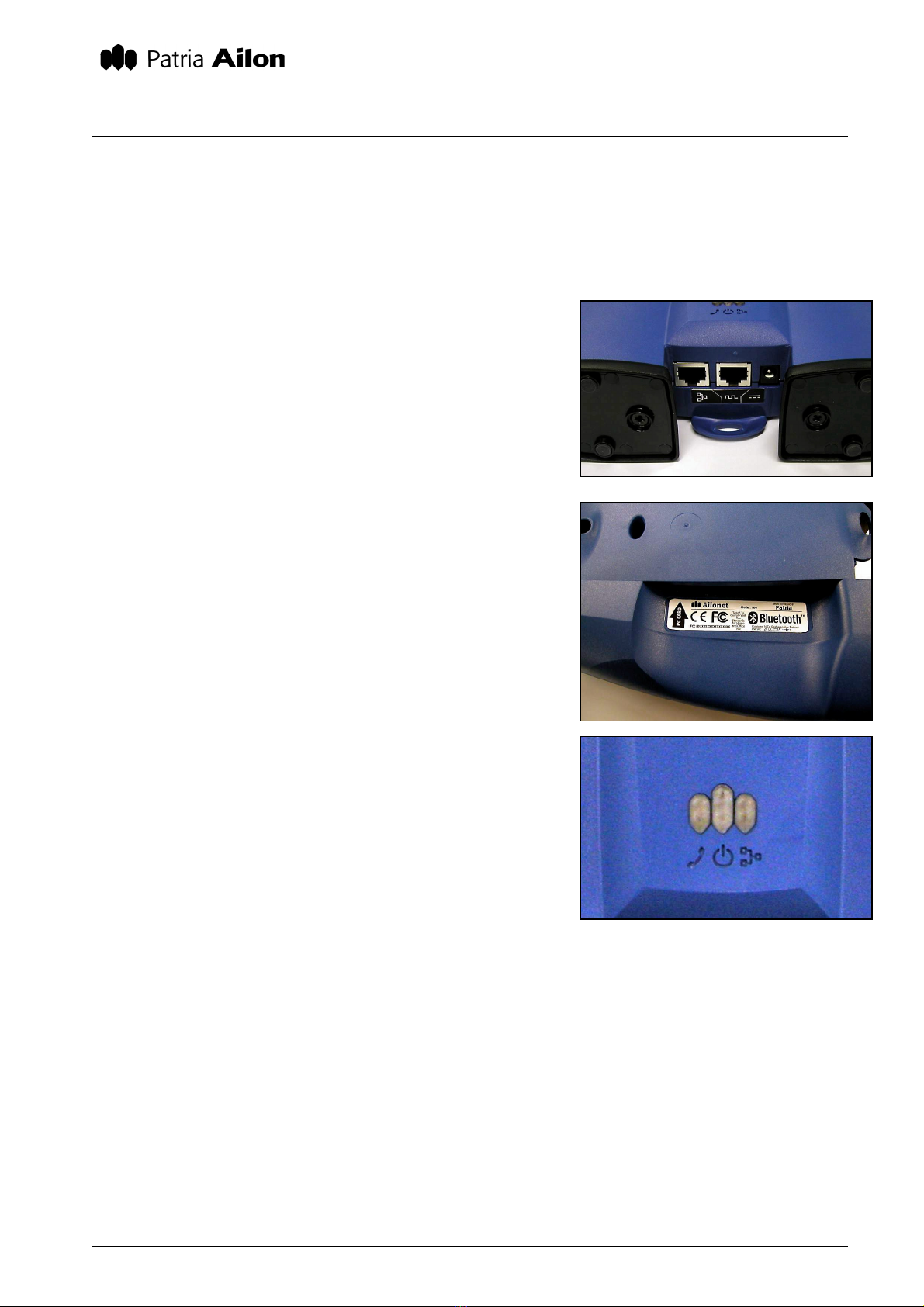
1.2.1 Connectors
All wire connectors are located on the bottom of Ailonet.
Ethernet (on the left) supports 10BASE-T and 100BASE-TX
connections, so it works with all modern Ethernet switches,
hubs, PC Ethernet cards, ADSL and cable modems. When
connecting Ailonet directly to a computer, use a special
twisted Ethernet cable.
Serial port (in the middle) supports RS-232 standard with
CTS/RTS handshake. The maximum speed of the serial port
is 115 kbps. Serial port can be used for initial setup or for
connecting external peripherals such as X10 controller.
Power input (on the right) accepts 8-14 VDC and supports
center negative feed.
PC Card slot can be found from behind of Ailonet. It supports
16-bit PCMCIA PC Cards. Cards must be installed and
removed when Ailonet is off. Refer to section “Supported PC
Cards” for further information about PC Card compatibility.
1.2.2 Indicators
The left-most led marked with a phone ear piece in this
revision of SW indicates a Bluetooth connection.
The led in the middle is power for indication. If the led blinks,
Ailonet is either starting up or shutting down.
The right-most led indicates for Ethernet connection. If the
led is lit half bright Ethernet link to network is established. If
the led blinks, data is been transferred.

MANUAL 21846
AILONET 100 6.6.2002
AILONET USER MANUAL Done
Copyright Patria Ailon Oy 2002. All rights reserved. 6/24
Figure 1 . Factory settings switch
is located on the back of Ailonet.
1.2.3 Switches
There are two switches located on the back of Ailonet. The
right-most switch is reserved for future use. The left-most
switch sets Ailonet into default factory mode in boot phase
erasing all user settings, installed plug-ins and any additional
information that is not part of Ailonet platform core software.
The switch can be used if the unit gets in a state where it
can’t be accessed normally. However, it is not
recommended to use the factory settings switch unless
the unit is absolutely dead and cannot be accessed in
any other method. In many cases prototype Ailonets
contain plug-in like additions tailored for customer use and these settings will be removed in factory
settings mode as well.
In order to set Ailonet into factory settings mode, the unit must be started with the factory settings
switch in down (ON) position. User defined settings done in factory settings mode are store nor-
mally, but the switch must be switched in up (OFF) position before the unit is restarted.

MANUAL 21846
AILONET 100 6.6.2002
AILONET USER MANUAL Done
Copyright Patria Ailon Oy 2002. All rights reserved. 7/24
1.3 System Setup
1.3.1 First Connection Using Serial Port
By default Ailonet serial port is configured for a PC with direct cable connection. Use supplied se-
rial port cable (RJ45 – D9) to make the physical connection between Ailonet’s and PC’s serial
ports. To configure Windows 98/Me/2000/XP properly for direct cable connection, refer to Windows
help (Start->Help) with keyword “Direct Cable Connection”.
Make the direct cable connection using the following parameters:
Speed: 38 400 bps
Handshaking: CTS/RTS (or Hardware)
Data bits: 8
Stop bits: 1
Parity: None
Username: dialin
Password: dialin
1.3.2 First Connection Using Bluetooth
The Ailonet Bluetooth network is configured by default to be discovered publicly. Ailonet Bluetooth
device name, PIN code (optional) and IP address can be found from CONFIGURATION STATUS
LIST – AILONET SAMPLE INFORMATION document delivered with the unit.
To access Ailonet from a Bluetooth enabled PC or PDA, use web browser to connect to
https://192.168.5.1/
(please verify the IP address from CONFIGURATION STATUS LIST – AILONET SAMPLE IN-
FORMATION)
1.3.3 First Connection Using 802.11b
Ailonet can be accessed via 802.11b network, if both PC/PDA and Ailonet are equipped with IEEE-
802.11b network PC Cards. See section “Supported PC Cards” for further information.
DHCP configuration, network name, encryption key and possible fixed IP address can be found
from CONFIGURATION STATUS LIST – AILONET SAMPLE INFORMATION document delivered
with the unit.
NOTICE: If Ailonet is configured to be a DHCP Client for 802.11b, it can not be accessed from
802.11b network – it can only act as a gateway from another interface (Bluetooth, Ethernet, etc.) to
802.11b. This is due to fact that there’s no easy way of finding out Ailonet’s 802.11b IP address.
To access Ailonet via 802.11b, use web browser to connect to
https://192.168.102.1/
(please verify the IP address from CONFIGURATION STATUS LIST – AILONET SAMPLE IN-
FORMATION)

MANUAL 21846
AILONET 100 6.6.2002
AILONET USER MANUAL Done
Copyright Patria Ailon Oy 2002. All rights reserved. 8/24
1.3.4 First Connection Using Ethernet
PC can be connected directly to Ailonet using so called twisted Ethernet cable. PC and Ailonet can
also be connected together with a hub using traditional Ethernet cables.
DHCP configuration and possible fixed IP address can be found from CONFIGURATION STATUS
LIST – AILONET SAMPLE INFORMATION document delivered with the unit.
NOTICE: If Ailonet is configured to be a DHCP Client for Ethernet, it can not be accessed from
Ethernet – it can only act as a gateway from another interface (Bluetooth, 802.11b, etc.) to
Ethernet. This is due to fact that there’s no easy way of finding out Ailonet’s Ethernet IP address.
To access Ailonet via Ethernet, use web browser to connect to
https://192.168.100.1/
(please verify the IP address from CONFIGURATION STATUS LIST – AILONET SAMPLE IN-
FORMATION)
1.3.5 After First Connection Is Established
When the first connection is established, your web browser might ask a confirmation for a certifi-
cate. You must accept it in order to proceed. After that Ailonet asks for administrator’s username
and password. These can be found from CONFIGURATION STATUS LIST – AILONET SAMPLE
INFORMATION document delivered with the unit. It suggested that the password is changed dur-
ing the first connection. For further information, see section 1.3.8, Security.
If there’s trouble in connecting Ailonet in the future, original factory settings can be restored using
Factory Settings Switch. See section 1.2.3 Switches for further details.
1.3.6 Selecting User Interface Language
User interface language can be changed from the top right corner of the screen by clicking appro-
priate flag. Currently English and Finnish are supported.

MANUAL 21846
AILONET 100 6.6.2002
AILONET USER MANUAL Done
Copyright Patria Ailon Oy 2002. All rights reserved. 9/24
1.3.7 Selecting Internet Interface
Internet interface means the network Ailonet uses to connect to outside world. Quite often the in-
terface is connected to Internet via Internet Service Provider. From Ailonet’s side there can only be
one external interface, which is one of the following:
–Ethernet
–802.11b
Internet interface is selected in Ailonet user interface by browsing to SETTINGS->Internet Inter-
face.
Internet interface can not be used for local/personal area network (LAN/PAN) at the same time. For
example if Ethernet is selected to be Internet interface, only Bluetooth and 802.11b can be used as
local interfaces (for LAN/PAN), if network traffic is intended to be routed through Ailonet.
1.3.8 Security
All the wireless interfaces are unprotected in factory settings in order to ease the initial setup. First
thing for administrator is to make sure the wireless connections are safe and unauthorized parties
can not use them.
Administrator and Dial-in Passwords:
Administrator’s username (admin) and password are common for all interfaces. For dial-in connec-
tion through a modem, PPP authentication username (dialin) and password are separate from ad-
ministrator’s password. Change both of these passwords by browsing to SETTINGS->Password.
Protecting Bluetooth Connections:
Bluetooth security features can be configured at SETTINGS->Bluetooth Security. There are three
different security features available: Encryption, PIN code and Mode. PIN code usage is defined by
the authentication selection on the top of screen:
–No authentication means that connection without prior pairing is allowed
–Authentication means that PIN code is requested and pairing required
–Authentication & Encryption means that PIN code is requested, pairing required
and the data transfers are encrypted if one of the connecting parties request it
PIN code is set by entering the code into “New PIN” and “Re-enter PIN” fields. Old PIN code must
be entered into “Old PIN” field. Refer to CONFIGURATION STATUS LIST – AILONET SAMPLE
INFORMATION for correct PIN number. Maximum length for PIN code is 16 characters and it can
contain numbers and letters.
Mode controls how Ailonet advertises itself in Bluetooth network. Non Discoverable/Non Connect-
able means that Ailonet do not respond to Bluetooth inquiries and do not allow incoming connec-
tions. Connectable means that Ailonet allows incoming Bluetooth connections with earlier paired
devices, but does not respond to inquiries. Discoverable/Connectable means that it responds to
inquiries and allows incoming connections.

MANUAL 21846
AILONET 100 6.6.2002
AILONET USER MANUAL Done
Copyright Patria Ailon Oy 2002. All rights reserved. 10/24
Protecting 802.11b Connections:
The actions protecting 802.11b connections must first be done in Ailonet and after that in terminal
(PC, PDA). Browse to SETTINGS->802.11b Settings and enter your private network name into
Network name field. After that enter a 5 character encryption key into Encryption key field. Accept
the changes after which your browser gives a notification about disconnection. This is due to
802.11b network changes you just made. Now make the same changes into your terminal’s
802.11b settings. By doing that your 802.11b connections are protected in the future.

MANUAL 21846
AILONET 100 6.6.2002
AILONET USER MANUAL Done
Copyright Patria Ailon Oy 2002. All rights reserved. 11/24
1.4 Supported PC Cards
Modems:
–Nokia CardPhone GSM modem
–Nokia CardPhone2 GSM modem
–Nearly all PSTN modems with AT command interface
802.11b Cards:
–Orinoco 802.11b Silver
–Orionoco 802.11b Gold

MANUAL 21846
AILONET 100 6.6.2002
AILONET USER MANUAL Done
Copyright Patria Ailon Oy 2002. All rights reserved. 12/24
2. ADMINISTRATION
2.1 Shutdown And Restart
While it is possible to turn Ailonet safely off by disconnecting the power cord, it is recommended
that you always use “Shutdown” button on the user interface to increase the life span of internal
UPS.
2.1.1 Shutdown
Shutdown step-by-step
1. In Ailonet’s user interface, browse to POWER menu
2. Press Shutdown hyperlink on the menu
3. Confirm the shutdown by clicking Yes
2.1.2 Restart
Restart step-by-step
1. In Ailonet’s user interface, browse to POWER menu
2. Press Restart hyperlink on the menu
3. Confirm your choice by clicking Yes

MANUAL 21846
AILONET 100 6.6.2002
AILONET USER MANUAL Done
Copyright Patria Ailon Oy 2002. All rights reserved. 13/24
2.2 Plug-ins
Plug-ins are small applications that are available for Ailonet users. Using plug-ins, you can auto-
mate for example device functions in Bluetooth network or be able to control devices remotely with
a mobile phone or PDA. Installed plug-ins are located in “PLUGINS” menu in Ailonet user interface.
2.2.1 Installing a Plug-in
When installing a Plug-in package, it must be on stored on hard drive of the computer you’re using
for browsing Ailonet’s user interface.
Installing a plugin step-by-step
1. Download or copy a Plug-in package to computer hard disk
2. In Ailonet’s user interface, browse to PLUGINS->Install
3. Press “Browse…” button and select the Plug-in package from the computer hard disk
4. Press “Send” button
5. Reboot after successful transfer
Installed plug-in will become available in Ailonet user interface in the “PLUGINS” menu.
2.2.2 Removing a Plugin
Installed plug-ins can be removed as well. Need for this might be a new version of the plug-in or
simply Ailonet’s memory is getting full and the plug-in is obsolete.
Removing a plugin step-by-step
1. In Ailonet’s user interface, browse to PLUGINS->Remove
2. Select the plug-in from the list
3. Double-check that the plugin you have chosen is the one you need to remove
4. Press “Remove Plugin” button

MANUAL 21846
AILONET 100 6.6.2002
AILONET USER MANUAL Done
Copyright Patria Ailon Oy 2002. All rights reserved. 14/24
2.3 Settings
Settings define how Ailonet uses its interfaces. In addition time and date, several security aspects
and network settings are configured here.
By browsing into SETTINGS menu, Ailonet shows general information about the unit and a visual
presentation about current network configuration.
2.3.1 Time and Date
Installed plugins can use time and date. Ailonet contains a battery backed real-time clock, which
maintains the clock even if the unit not powered.
Changing time and date step-by-step
1. In Ailonet’s user interface, browse to SETTINGS->Time and date
2. Enter time into fields in hours:minutes:seconds format
3. Enter date into fields in day:month:year (4 digits) format
4. Press Confirm button
2.3.2 System Update
Ailonet system software can be updated with System Update function.
Installing system update package step-by-step
1. Download or copy a system update package to computer hard disk
2. In Ailonet’s user interface, browse to PLUGINS->System update
3. Press “Browse…” button and select the system update package from the computer hard disk
4. Press “Send” button
5. Reboot after successful transfer

MANUAL 21846
AILONET 100 6.6.2002
AILONET USER MANUAL Done
Copyright Patria Ailon Oy 2002. All rights reserved. 15/24
2.3.3 Internet Interface
Internet interface defines interface which Ailonet uses to connect to ISP. Very often Internet con-
nection is brought via cable or DSL modem using Ethernet connection to Ailonet. However, Inter-
net interface connection can also be 802.11b. For further information about selecting external in-
terface, see section 1.3.7, Selecting Internet Interface.
Changing external interface (WAN) step-by-step
1. In Ailonet’s user interface, browse to SETTINGS->Internet Interface
2. Select appropriate interface from External interface list
3. Press Confirm button

MANUAL 21846
AILONET 100 6.6.2002
AILONET USER MANUAL Done
Copyright Patria Ailon Oy 2002. All rights reserved. 16/24
2.3.4 Bluetooth
Ailonet supports at the moment the routing of traffic coming through Bluetooth to other interfaces or
networks of Ailonet. Ailonet can therefore function as an access point for other Bluetooth devices
to the external network. With the Bluetooth settings, the discoverability of Ailonet on the device in-
quiries of other devices and the settings of bonds and connections can be influenced.
The controlling of discoverability and connections is simple. The user can choose whether Ailonet
can be discovered with Bluetooth device inquiries and whether Bluetooth connections are allowed.
Pairing always requires a PIN code. You can ask for authentication for connections, in which case
Ailonet requires pairing when establishing a connection. The connection initiator is asked to enter
PIN code, and if the code is correct, he is allowed to establish a connection.
From the Bluetooth settings front page you can see, to which devices Ailonet is paired and to
which it has a connection. The pairings made on the page Device discovery appear updated on the
front page. The device name, Bluetooth address and device class can be seen on this list. The de-
vice class indicates the type of Bluetooth device.
2.3.4.1 Settings
The Ailonet name which can be discovered as the device name in the network is defined on the
page Bluetooth: Settings.
2.3.4.2 Security
On the page SETTINGS->Network: Bluetooth: Security the security of Ailonet Bluetooth connetions
can be defined. The page contains the choices on PIN code inquiry, Ailonet discoverability and on
accepting the connections to be taken to Ailonet. The Change PIN code function can be found on
the same page. The PIN code inquiry can be switched off by choosing no authentication, in which
case a connection can be established without a PIN code inquiry. If the option Authentication is
chosen, no connection can be established without bonding. If Authentication & Encryption is cho-
sen, encryption is used in the connection, if possible.
Changing PIN code:
The PIN code can be easily changed by entering the old code in the field Change PIN code: PIN
Code. The new PIN code is first entered in the field New PIN and again in Re-enter PIN.
Security:
This choice defines, whether Ailonet can receive a Bluetooth connection or whether any device can
bond to Ailonet. If Not discoverable is chosen, Ailonet cannot be found in device inquiries and it
doesn't allow connections or bonding. If the option Connectable is chosen, Ailonet cannot be found
in device inquiries and Ailonet cannot be bonded to, but devices previously bonded to Ailonet can
connect to Ailonet. If Discoverabe/Connectable is chosen, a Bluetooth device can bond to or es-
tablish a connection to Ailonet and can be found on device inquiries.

MANUAL 21846
AILONET 100 6.6.2002
AILONET USER MANUAL Done
Copyright Patria Ailon Oy 2002. All rights reserved. 17/24
2.3.4.3 Device Discovery
Ailonet can be bonded to another Bluetooth device, but Ailonet cannot establish Bluetooth connec-
tions. The bonding is done by going to the subpage Device discovery and by choosing Inquiry. The
found devices appear on the page. The device information contains the name, address and class
of the device, the Services link and the Bond link. If you choose Services, you can see the services
offered by the Bluetooth device. By choosing Bond you can bond the device to Ailonet. When
Ailonet bonds to a Bluetooth device, after the connection has been established, the device appears
on the list of bonded devices which can be seen on the Bluetooth front page and on the subpage
Device discovery.
By clicking SETTINGS->Bluetooth gives a brief overview of current connections and bonded de-
vices. Ailonet’s own Bluetooth information including device name and Bluetooth address is also
shown.
Modifying Bluetooth settings step-by-step
1. Choose Ailonet name. From the subpage Settings, the Ailonet name which can be discov-
ered in the network to other devices, can be changed.
2. Confirm the changes by clicking Confirm.
3. Go to subpage Security.
4. Choose authentication, if you wan to prevent contacting Ailonet without a code.
5. Change PIN-code.
6. Choose not discoverable, connectable, connectable/discoverable.
7. Confirm changes by clicking Confirm Continue, if you want to bond Ailonet to another Blue-
tooth device.
8. Go to subpage Device discovery.
9. Choose the device to be bonded. If the device is not on the list, make a new inquiry by click-
ing the link Inquiry. If the device can still not be found, its discovery has been denied or the
device power is off.
10. Choose the Bond link to bond the device and enter the required PIN code. The device ap-
pears on the bonded devices list on the Bluetooth front page.

MANUAL 21846
AILONET 100 6.6.2002
AILONET USER MANUAL Done
Copyright Patria Ailon Oy 2002. All rights reserved. 18/24
2.3.5 802.11b
802.11b settings how define how radio card installed in PC Card slot works. 802.11b settings con-
tain network name, network mode, handshaking and encryption key. In addition administrator must
define DHCP functionality, IP address, gateway and DNS name servers. Notice, that these settings
affect only to 802.11b interface.
In 802.11b networks Network name differs separate radio networks from each other. If there are
several 802.11b networks in the same area, users can choose the right one with the network
name. Mode is currently only AdHoc. Enabling CTS/RTS flow control may help in a situation,
where in rapid data transfers a lot of data packets are lost. Using Encryption key improves security
of wireless data transfers, because all the data is encrypted before wireless transmission. Notice,
that in some 802.11b PC Cards the length of the encryption key is limited. Refer card’s user man-
ual before using encryption.
If 802.11b is selected to be external interface (see section 2.3.3, Internet Interface for further
information), the settings are defined by the network service provider. If the connection is with fixed
IP address, DHCP mode must be selected to be None and administrator must fill the fields below
with network service provider defined settings. If the connection supports dynamic IP address,
DHCP mode must be selected to be Client. In this case there is no need for further Ethernet set-
tings modifications, because all the settings are modified automatically by Ailonet.
If 802.11b is used for LAN, it pays off to select DHCP mode to be Server. That way all the de-
vices connected to 802.11b network can get their IP addresses and other network settings from
Ailonet and administration of the wireless LAN becomes easier. In this case IP address field is
filled with for example 192.168.0.1, Netmask with 255.255.255.0 and Gateway and DNS fields are
left blank.
Modifying 802.11b settings step-by-step
1. In Ailonet’s user interface, browse to SETTINGS->802.11b Addresses
2. Select DHCP Mode (If Client, go to step 8)
3. Enter Ailonet’s IP address in Ethernet network
4. Enter Netmask
5. Enter Gateway IP address
6. Enter Primary DNS IP address
7. Enter Secondary DNS IP address
8. Press Confirm button
9. In Ailonet’s user interface, browse to SETTINGS->802.11b Settings
10. Enter 802.11b network name without spaces
11. Selected Mode (only AdHoc supported at the moment)
12. Select RTS/CTS flow control on/off
13. Enter Encryption key or leave the field blank (no encryption)
14. Press Confirm button

MANUAL 21846
AILONET 100 6.6.2002
AILONET USER MANUAL Done
Copyright Patria Ailon Oy 2002. All rights reserved. 19/24
2.3.6 Ethernet Settings
Ethernet settings define DHCP functionality, IP address, gateway and DNS name servers. Notice,
that these settings affect only to Ethernet interface.
If Ethernet is selected to be external interface (see section 2.3.3, Internet Interface for further
information), the settings are defined by the network service provider. If the connection is with fixed
IP address, DHCP mode must be selected to be None and administrator must fill the fields below
with network service provider defined settings. If the connection supports dynamic IP address,
DHCP mode must be selected to be Client. In this case there is no need for further Ethernet set-
tings modifications, because all the settings are modified automatically by Ailonet.
If Ethernet is used for LAN, it pays off to select DHCP mode to be Server. That way all the de-
vices connected to Ethernet can get their IP addresses and other Ethernet settings from Ailonet
and administration of the LAN becomes easier. In this case IP address field is filled with for exam-
ple 192.168.0.1, Netmask with 255.255.255.0 and Gateway and DNS fields are left blank.
Modifying Ethernet settings step-by-step
1. In Ailonet’s user interface, browse to SETTINGS->Ethernet
2. Select DHCP mode (If Client, go to step 8)
3. Enter Ailonet’s IP address in Ethernet network
4. Enter Netmask
5. Enter Gateway IP address
6. Enter Primary DNS IP address
7. Enter Secondary DNS IP address
8. Press Confirm button

MANUAL 21846
AILONET 100 6.6.2002
AILONET USER MANUAL Done
Copyright Patria Ailon Oy 2002. All rights reserved. 20/24
2.3.7 Serial Port Settings
Serial port settings define how Ailonet uses its integrated serial port. Modifiable settings are speed,
flow control, initialization string and if Ailonet answers to incoming calls.
In addition, serial port settings define if a local computer is connected to Ailonet via serial port (di-
rect cable connection) or is there a modem connected (modem). If a direct cable connection is
preferred in connecting a computer to Ailonet, Allow incoming connections must be enabled. When
using Microsoft Windows operating system in the computer, Microsoft Windows modem emulation
selection must also be enabled. In this case administrator must create a new direct cable connec-
tion profile in Windows, where connecting interface is the COM port connected to Ailonet.
It is recommended to enable Hardware Flow control to ensure trouble-free communication. With
initialization strings special features of modems can be enabled and disabled (packing, speed ad-
just, etc.) Refer to modem user manual for further information. If Enable incoming connections is
enabled, Ailonet will answer to incoming calls. Number of rings before answering defines the num-
ber of rings before Ailonet answers to an incoming call and tries to form a PPP connection. The
username for connecting party is dialin and password is set at SETTINGS->Password.
Modifying serial port settings step-by-step
1. In Ailonet’s user interface, browse to SETTINGS->Serial port
2. Select serial port Function
3. Select serial port Speed
4. Select Flow control
5. Enter Drop idle line time in minutes
6. Enter Init string
7. Select, if incoming connections are allowed
8. Select if Microsoft Windows modem emulation is used with direct cable connection
9. Enter the Number of rings before answering
10. Press Confirm button
Table of contents
Popular Wireless Access Point manuals by other brands


RTS
RTS ROAMEO AP-1800 installation instructions

TP-Link
TP-Link Omada Pro Quick installation guide

Juniper
Juniper AX411 quick start guide

Draytek
Draytek VigorAP 1000C user guide

D-Link
D-Link DWL-G700AP - AirPlus G Access Point manual

Moxa Technologies
Moxa Technologies AirWorks AWK-3121 Quick installation guide