ASSEMBLY INSTRUCTIONS (continued)
ASSEMBLY INSTRUCTIONS (continued)
FUNCTION AND OPERATION (continued)
5. CUSTOM MODE (nighttime operation only):
● In "CUSTOM" mode, the light turn on full brightness (2700K)
at dusk and off at dawn automatically.
● Set motion sensor operation to go on at a specific time.
Turn the wall switch "OFF", and turn it "ON" twice within
3 seconds. The light will go into motion-sensor operation at
the specified time every night. The light turns off automatically
at dawn.
For example, a homeowner wants to have the light stay on
high-level brightness from dusk to 8pm, and would like the light
to go into "AUTO" motion sensor mode. To achieve this, the
light homeowner will turn the wall switch "OFF", and turn it
"ON" twice within 3 seconds. This sets the time the light goes
into "AUTO" mode every day, the light will behave the same way.
To revert back to Default, turn the wall switch "OFF" and then turn it "ON" after 5 seconds.
Note: You can adjust the low-level brightness(0~50%) by using the low-level brightness(0~50%) knob on
the backplate (See Fig.6).
When light units are linked, the Set motion sensor operation to go at a specific time is also linked when
MODE settings are in Custom.
6. RF Linking Network Setup
From all the light units, select one as the main unit and the others as the sub-units;
First to setup all the sub-units by press the Link button twice within 3 seconds, the sub-units will flash once every 1
second meaning it is waiting to receive matching signal from the main light.
Then to setup the main unit by press and hold the Link button for 5 seconds, the main unit will flash slowly
(once every 3 seconds), and when the sub-units have paired with the signal, the sub-units will stop flashing
confirming it have paired with the main unit. (if pairing not successful, the sub-unit will keep flashing).
When all the sub-units have stop flashing, press the Link button on the main unit once to complete the pairing process.
(the main unit will stop flashing)
After complete the pairing process, any light within the Link group range can send or receive the photo sensor or
motion sensor signal from the other light and response accordingly.
Note: Maximum link up to 10 units per link group, each light can link within 120ft apart.
RF Linking
a. Photo Sensor Linking
When the Photo Sensor detect that the ambient brightness is less than the LUX set value.
● In "Auto" mode, the light turns on to Low-Level brightness (2700K) and send out a comprehensive signal.
1) Linking other lamps set in "Auto" mode to enter Low-Level brightness
2) Linking other lamps set in "3H", "PC", or "Custom" mode to enter High-Level brightness.
● In "PC", "3H", or "Custom" mode, the light turns on to High level brightness and send out a comprehensive signal.
1) Linking other lamps set in "Auto" mode to enter Low-Level brightness (2700K).
2) Linking other lamps set in "PC", or "3H" mode to enter High-Level brightness (5000K).
3) Linking other lamps set in "Custom" mode to enter High-Level brightness (2700K).
Page 5 of 8
211019
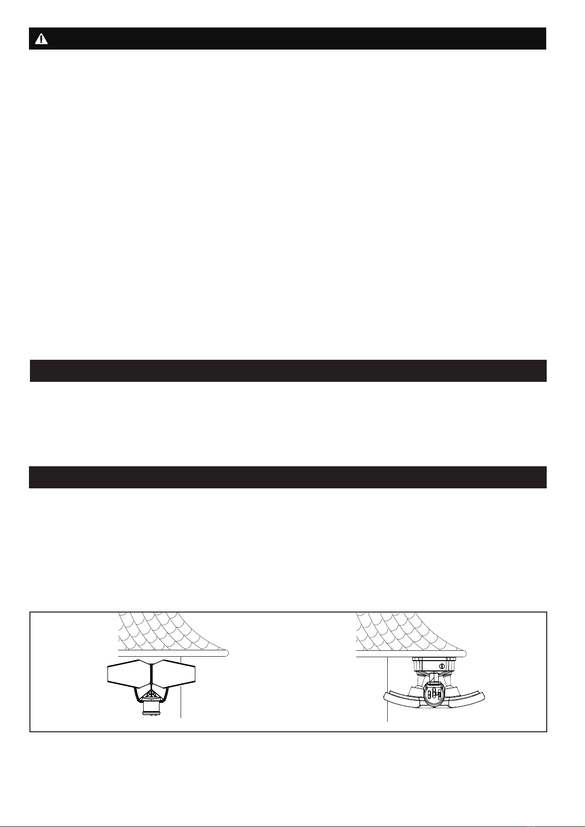
Fig. 7
“AUTO” or
“3H” Mode
Manual
Override
Manual Override Operation Diagram
Turn wall switch OFF-ON-OFF-ON
in 0.5~3 Seconds
Turn wall switch OFF-ON-OFF-ON
in 0.5~3 Seconds
b. Motion Detect Linking
When the Motion Sensor detects
● In "Auto" mode, the lamp sends out a comprehensive signal to all the linked lamps to automatically switch to
High-Level brightness (5000K) and remains on for predetermined time you set (30s/1min/3min).
● In "3H" or "Custom" mode,
1) During the start of "3H" or "Custom" mode, the lamp will remain High-Level brightness and turn off the motion
sensor until 3 hours or the custom set time is up.
2) Once the "3H" or "Custom" set time is up, the lamp will turn on motion sensor and switch to "Auto" mode where
the lamp sends out a comprehensive signal to all the linked lamps to automatically switch to High-Level
brightness (5000K) and remains on for predetermined time you set (30s/1min/3min).
When the Photo Sensor detects that the ambient brightness is greater than the LUX set value,
●A comprehensive signal from the volunteers to inform all the Linking lamps to turn off automatically.