Patriot Lighting E6956W User manual

Questions, problems, missing parts?
Before returning to your retailer, call our customer service at 1-800-887-6326
Monday – Friday 9:00 a.m. – 5:00 p.m. CST
Sku Number: 356-9243/9244
INDUCTION LAMP
Model Number: E6956W/E6956BZ
SAFETY INFORMATION
Please read and understand this entire manual before attempting to assemble, operate or install the product.
WARNING
• Turn off electricity at main fuse box (or circuit breaker box) before beginning installation by removing fuse (or switching off
circuit breaker).
• Be careful not to damage or cut the wire insulation (covering) during fixture installation. Do not permit wires to contact any
surface having a sharp edge. To do so may damage or cut the wire insulation, which could cause serious injury or death from
electric shock.
CAUTION
• All electrical connections must be in agreement with local codes, ordinances or the national electric code (NEC). Contact your
municipal building department to learn about your local codes, permits and/or inspections.
• Risk of fire – most dwellings built before 1985 have supply wire rated for 140°F/60ºC. Consult a qualified electrician before
installation.
• Only general ON/OFF wall switch applys for this fixture, the dimmable wall switch shoudn’t be required.
Maximum Wattage: 29 W
Working Temperature Range: -40F ~ 1130F
Page 1 of 9
PACKAGE CONTENTS
AA BB DD
CC EE
HARDWARE CONTENTS Note: Hardware not shown actual size.
A
B
C
D
Mounting Screw
X2
Mounting Bracket Screw Fixture Mounting Screw
Mounting Strap Decorative cover
#8/32X1/2 in #6/32 X1/2 in #10/24 X1/4 in

PREPARATION
Before beginning assembly, installation or operation of product, make sure all parts are present. Compare parts with package
contents list and diagram on previous page. If any part is missing or damaged, do not attempt to assemble, install or operate the
product. Contact customer service for replacement parts.
Tools Required for Assembly (not included): Screwdriver, Phillips Screwdriver, Pliers, Electrical Tape, Wire Cutters, Safety
Glasses, Ladder, Wire Stripper.
Page 2 of 9
DD
B
DD
A
A
EE
DD
12
Important to Know
1. This fixture requires a 120 VAC, 60 Hz power source.
2. For general safety and to avoid any possible damage to the sensor, be sure the power is switched "off" before adjustment.
3. Motion sensor: turns light ON automatically when motion is detected and turns light OFF automatically when motion stops.
4. Photocell keeps the light OFF during daylight hours.
Note: Fixture can be wall mounted or eave mounted.
Wall Mounted Eave Mounted
Light fixture and sensor should be mounted as shown above when installed (depending upon type of installation)
Before installing the light fixture under an eave, the sensor head must be rotated as shown in the next two steps for
proper operation and to avoid the risk of electrical shock.
For eave mounted only:
Swing the sensor head towards the mounting bracket. 5RWDWHWKHVHQVRUKHDGFORFNZLVHÛVRWKHFRQWUROVIDFHGRZQ
Controls
Mounting Bracket
Controls
Controls
CC AA
ASSEMBLY INSTRUCTIONS
Turn off the power at fuse or circuit box.
Installation Steps
1. The fixture mounting bracket(A) is
pre-assembled on the light fixture(B).
Unscrew both the decorative cover(DD)
and the fixture mounting screw(EE) in
order to remove the mounting
bracket(A).
2. Install the mounting strap(CC) to the
outlet box with the stamped
word “FRONT” facing away from
the outlet box, using two mounting
screws(AA) that best fit the outlet box.
Mounting bracket(A) should sit flush
against wall surface when secured.
(Choose one matching pair of suitable
mounting screws(AA) from the 3 pairs
provided).
FRONT

Page 3 of 9
ASSEMBLY INSTRUCTIONS(contiuned)
FUNCTION AND OPERATION
A
3
A
BB
CC
4
3. Pull out the source wires from the outlet
box.Connect the black wire from the
outlet box to the “L” interface of the
terminal station on the mounting
bracket(A). Connect the white wire from
the outlet box to the “N” interface of the
terminal station on the mounting bracket(A).
Carefully tuck the wires back into the outlet box.
NL
4. Place mounting bracket(A) against the
outlet box, insert the mounting bracket
screw(BB) through the mounting
bracket hole, thread mounting bracket
screw(BB) into the center hole of the
mounting strap(CC). Tighten the
mounting bracket screw(BB) securely.
Ÿ:KHQPRXQWLQJWRDZDOOWKH³83´DUURZPXVWSRLQWupward.
Ÿ:KHQPRXQWLQJWRDQHDYHWKH³83´DUURZPXVWSRLQWtoward the building.
DD
B
DD
A
EE DD
5
5. Attach the back plate(B) of the light
fixture to the mounting bracket(A),
secure it with the fixture mounting
screw(EE). Then push the decorative
cover(DD) firmly into the fixture
mounting screw(EE) hole on the light
fixture.
Adjusting the Sensor Head:
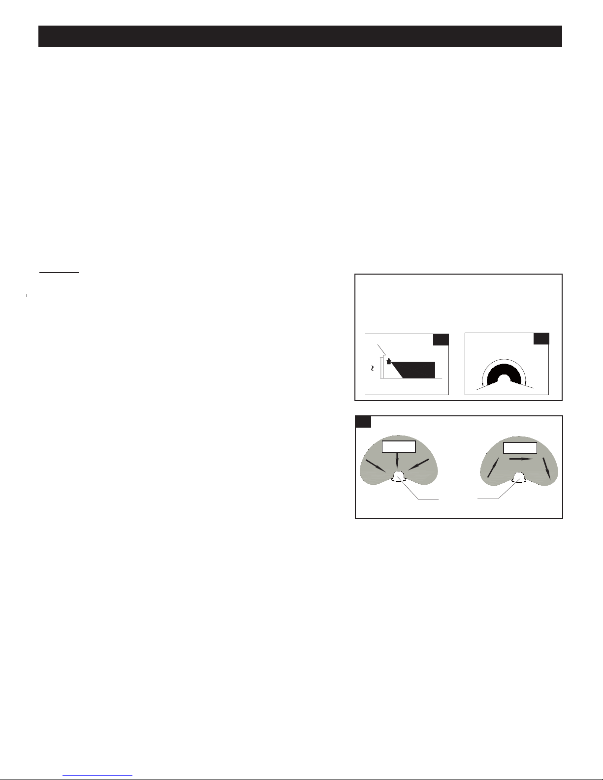
1. a: Aim sensor head toward desired detection area, maintaining a 5° - 40° downward angle to allow
moisture to drain. (See Fig.1)
Note: Make sure sensor head is positioned with control knob facing towards the ground.
DD
D
Adjustment Sensor Lower For Short Coverage
Adjustment Sensor Higher For Long Coverage
Fig.2-1 Fig.2-2
Fig.1
b: You can rotate the sensor head up and down to change the coverage area . Walk through the
detection zone at the farthest distance you wish to detect motion.
2. Range set too high may increase false triggering. (See Fig.2-1,2-2)
1. You can adjust the sensitivity of the motion sensor by using the “SENSITIVITY” selector
located on the right side of the bottom surface of the sensor. (See Fig.4)
2. Adjust motion sensor sensitivity to HIGH (H), MEDIUM (M), or LOW (L) to achieve desired
performance.
3. Approximate range for each setting: 25 ft. (L), 45 ft. (M), 70 ft. (H).
Fig.3
1. Gently grasp the light heads(C) and tilt them up or down, left or right to adjust the light coverage
DUHD.HHSWKHOLJKWKHDGVDWOHDVWÝPPDZD\IURPWKHVHQVRU6HH)LJ2. .HHSWKHOLJKWKHDGVÛEHORZKRUL]RQWDOWRDYRLGZDWHUGDPDJHDQGHOHFWULFDOVKRFN
Adjusting the Light Head:
Sensitivity of Motion Sensor:
DD
C
Fig. 4
Mode
Mode
TEST
AUTO
RESET
3MIN
1MIN
5S
5MIN
L
M
H
CUSTOM
SETTINGS
SENSITIVITY
Sensitivity
Choose a mode by sliding the switch on the bottom of the sensor. (See Fig.4)
Note: When power is first applied, the light will turn on to 100% brightness. The sensor
will take 30 seconds to warm up.
1. Test mode (daytime or nighttime operation )
Ɣ6OLGHWKHVZLWFKRQWKHOHIWVLGHRIWKHVHQVRUWRWKH³7(67´SRVLWLRQ6HH)LJƔ:LWKWKHSRZHURQWKHOLJKWWXUQs to low-level brightness automatically.
Ɣ7KHOLJKWWXUQVWRKLJKOHYHOEULJKWQHVVZKHQPRWLRQLVGHWHFWHGDQGVWD\VRQDVORQJDVthe motion continues. Then it reverts back to low-level brightness about 5 seconds after
motion is no longer detected.
Note: You can adjust the low-level (0~50%) and high-level (50~100%) brightness by
using the brightness switch on the back plate. (See Fig. 5)
6. With silicone caulking compound, caulk completely around
where the mounting bracket meets the wall surface.
CAUTION: Be sure to caulk completely where the
mounting bracket meets the wall surface to prevent
water from seeping into the outlet box.
Fig. 5
HIGH LEVEL
75% 25%
100%
50% 50%
0
LOW LEVEL

Page 4 of 9
FUNCTION AND OPERATION(contiuned)
2. AUTO MODE (nighttime operation only)
ƔTo shift to “AUTO” mode, slide Time Delay switch to the desired time setting (between 5 seconds and 5 minutes). At dusk,
the light turns on to pre-selected low-level brightness. When motion is detected, the light turns to pre-selected high-level
brightness and stays on as long as motion continues. When the motion is no longer detected, the light at high-level
brightness remains on for the predetermined time you set (5S/1M/3M/5M), and then switches back to low level automatically.
Ɣ7KHOLJKWWXUQVRIIDXWRPDWLFDOO\DWGDZQNote: You can adjust the low-level (0~50%) and high-level (50~100%) brightness by using the brightness switch on the
back plate. (See Fig. 5)
3. CUSTOM SETTINGS MODE (nighttime operation only)
Ɣ$WGXVNWKHOLJKWZLOOWXUQVRQWRSUHVHOHFWHGKLJKOHYHOEULJKWQHVV$QGWKHOLJKWZLOOWXUQVRIIDXWRPDWLFDOO\DWGDZQƔ7RVZLWFKWRWKH³$872´PRGHDWWKHVSHFLILHGWLPHWXUQWKHZDOOVZLWFK³2))´WKHQWXUQLW³21´ZLWKLQVHFRQGVDW\RXUspecified time.And the light will switchs to “AUTO” mode automatically at the specified time every night. The light turns off
automatically at dawn. To revert to “CUSTOM SETTINGS” mode,turn the wall switch “OFF” then turn it “ON” within 5
seconds again.
Note: You can adjust the low-level (0~50%) and high-level (50~100%) brightness by using the brightness switch on the
back plate. (See Fig. 5)
Notes:
1. The sensitivity of the motion sensor will increase as the
environmental temperature gets cooler. You may wish to
make adjustments when the season changes.
For best performance, gently clean the lens with a soft
cloth every 1 or 2 months to assure maximum sensitivity.
2. For best performance, install fixture at least 8 feet above
the ground. At such a height, the fixture will provide a
detection distance of up to 70 feet at 77 degrees
Fahrenheit. (See Fig.6)
3. The sensor detects movement across a detection range
of 240 degrees. (See Fig.7)
4. The sensor will be more sensitive to motion across its
detection path than motion directly towards it. (See Fig.8)
5. To reduce possible nuisances, do not mount the fixture
near a heat source like an air conditioner, vent or furnace
exhaust, or in a direction facing any reflecting object or
other light source.
25'
8.0'
12.0'
70'
Where you install your fixture is important:
Be sure the light is mounted straight on the wall
or eave; otherwise, the detection distance may
be limited.
Fig. 6 Fig. 7
Motion
Least sensitive
Motion
Most sensitive
Sensor
Fig. 8
240 '

Page 5 of 9
USER GUIDE
Setting for single light through mobile device (Take IOS for example as below.
Android will be slightly different).
1. Search “Dualux BT” at Apple store
or Android Google Play. Download
the “Dualux BT” APP onto the
device.
4.If there is a light in bluetooth
cover range, the new light
will be shown in light list. And
the touch “Light 1”,App will
go to the step 5 interface.
And touch “ ” icon,App
will go to the step 8 interface.
5. Select “Test” in Manual
override and adjust “Detection
Distance” and “Brightness” as
desired. Then press “SAVE”.
Note: If your settings on the
“Manual override”mode forget
to save, the settings will be
performed for 2 minutes,then
the light will revert to phsical
switch’s control on the lamp.
3. Ensure the power to the light is turned ON. Touch “Search
for Lights” to search for existing lights.Make sure the
bluetooth on your devices is turned on and the the light is
turned on.Otherwise, the searching current light will be no
result.
2. Start the APP. Turn on the
Bluetooth in device settings.
Fig.1
Fig.4
Fig.2
Fig.3
Fig.5
6. Select “AUTO” in Manual override
and adjust “Motion Delay Time”,
“Detection Distance” and
“Brightness” as desired. Then
press “SAVE”.
Note: If your settings on the
“Manual override”mode forget
to save, the settings will be
performed for 2 minutes,then
the light will revert to phsical
switch’s control on the lamp.
Fig.6
Fig.3-1

Page 6 of 9
USER GUIDE (CONTINUED)
8. Press Fig.4“ ” icon,
select “Functions”, you can
choose “Test”, “AUTO”, or
“Custom Setting” which have
been adjusted to edit your
settings.
9. Press Fig.8 “Change image”.And
touch “take photo” to take a
photo .
9.1 Click “ ” to grasp a
your desired view
9.2 Click “ ” to take a photo.
9.3. Adjust the photo to trim
the photo’s desired size.
Then click “ ” .
7. Select “Custom Settings” in Manual
override. Adjust the “Duration” as
desired, the “4hr” is the default.The
light will turn to your setted high
level brightness for your setted
duaration,then turns to “AUTO”
mode. The setting will be avaliable
only at this night. Next night the
light will turn to “Clock time(End
Time”mode. Adjust the “Clock
Time”, the “9PM” is the default. The
light will turn to high level
brightness you set for the
pre-setted “Clock Time”, then turns
to “AUTO” mode at your
pre-setted time.
Note: If your settings on the
“Manual override”mode forget
to save, the settings will be
performed for 2 minutes,then
the light will revert to phsical
switch’s control on the lamp.
Fig.7
Fig.9
Fig.9-1
Fig. 8

Page 7 of 9
USER GUIDE (CONTINUED)
11. Press Fig.8 “Rename light” to
enter a name for the light,
Then press “Save”.
12. Press Fig.8 “Password” to set
the pasword for bluetooth
device, so that others need
password to connect this lamp.
10. Press Fig.9 “Change existing
photo” to choose a desired
image on your App.Then click
“Cancel” back to“Setting” menu
list.
Fig.10
Fig.11-1
9.5. Take back to “Light list”
interface,the photo shoud
show on the left of “Light 1”
9.4. App will turns to “change image”
interface.The photo should show
on it.
Fig.9-5
Fig.9-4 Fig. 11
Fig. 12

Page 8 of 9
USER GUIDE (CONTINUED)
12. 1 The password must be 4 to 6
alpha-numberic characters.
Enter new password and
verify it then press “Save”.
13. Press Fig.8 “Restore factory
defaults” to restore your settings
(only the light name and
password) to the original
conditions.
13.1 Keep pressing the “reset” button
on the light for 5 seconds, the
light will flash three times.
Then press “Back” button.
Note: The photo’s settings
can’t be restored by
using this function.
Note: 1. Manual control and App control independently.
2. The function which is executed is the lastest
settings.
3. When call again after power cut, the function will
revert to phsical switch’s control on the lamp.
4. For achieving the best performance,make sure the
wall switch is in “ON” state (daytime and
nighttime).
5. Once the power fails, the light will revert to phiscal
switch’s control on the lamp.
Fig. 13
Fig. 13-1
Fig. 12-1
Range Up to 70ft. (21.3m)(Varies with surrounding temperature)
Up to 240
29W
2600lm
120 VAC, 60Hz
Test, Auto,Customer setting,Manual
5s,1min,3min,5min
Iphone 4S or newer running IOS 8.0 x or later.
Android v4.4 or later
Phone must also have Bluetooth version 4.0 or later
Sensing angle
Electrical load - LED
Lumens
Power requirements
Operating modes
Time delay
Mobile device requirements

Page 9 of 9
To clean, turn off and wipe with a damp, non-abrasive cloth.
1) The light does not come on at all:
2) The light comes on during the day.
a) Make sure the wall switch and circuit breaker are on.
a) Make sure the motion sensor does not be installed in a relatively dark location.
b) Make sure the wiring is correct.
c) Make sure the Daylight turn-on(photocell) is in effect.
d) Make sure the motion sensor is aimed in the right direction to cover the desired area.
e) Make sure the outside air temperature is not close to the same as a person’s body heat.
If unable to fix any of the above issues,please consult a certified electrician.
FIVE-YEAR LIMITED WARRANTY: If, during normal use, this PATRIOT LIGHTING lighting fixture breaks or fails due to a
defect in material workmanship within five (5) years from the date of original purchase, simply bring this lighting fixture with the
original sales receipt back to your nearest MENARDS retail store. At its discretion, PARTIOT LIGHTING agrees to have the
product or any defective part(s) repaired or replaced with the same or similar PATRIOT LIGHTING product or part free of
charge, within the stated warranty period, when returned by the original purchaser with original sales receipt. This warranty; (1)
excludes expendable parts including but not limited to light bulbs; (2) does not cover damage that has resulted from abuse or
misuse; and (3) does not cover any losses, labor, injuries to persons/property or costs. This warranty does give you specific
legal rights and you may have other rights, which vary from state to state.
Questions, problems, missing parts?
Before returning to your retailer, call our customer service at 1-800-887-6326
Monday – Friday 9:00 a.m. – 5:00 p.m. CST
CARE AND MAINTENANCE
TROUBLESHOOTING
R
RR
R
FCC Statement
Any Changes or modifications not expressly approved by the party responsible for compliance could void the user's authority to
operate the equipment.
This device complies with part 15 of the FCC Rules. Operation is subject to the following two conditions:
(1) This device may not cause harmful interference, and
(2) this device must accept any interference received, including interference that may cause undesired operation.
Spare Parts List:
The following parts are available for re-order if damaged or missing. Call us toll-free at 1-800-887-6326
Assembly Kit
5569MM (1 SET) for 356-9243
5570MM (1 SET) for 356-9244
AA BB DD
CC EE
Mounting Screw
X2
Mounting Bracket Screw Fixture Mounting Screw
Mounting Strap Decorative cover
#8/32X1/2 in #6/32 X1/2 in #10/24 X1/4 in
This transmitter must not be co-located or operating in conjunction with any other antenna or transmitter.
This equipment complies with FCC radiation exposure limits set forth for an uncontrolled environment. This equipment
should be installed and operated with minimum distance 20cm between the radiator& your body.
This manual suits for next models
1
Table of contents
Other Patriot Lighting Floodlight manuals
Popular Floodlight manuals by other brands

Ritos
Ritos LY9601H Operation and maintenance manual

Acclaim Lighting
Acclaim Lighting Dyna Accent user guide

Nature Power
Nature Power 60 LED instruction manual

Kam Lighting
Kam Lighting DMX LASER 60 instruction manual

Platek
Platek NETTUNO Assembly instructions

HOLOPHANE
HOLOPHANE Predator Installation and maintenance manual