Patriot 75cm Offset Antenna Guide

INSTALLATION &
ASSEMBLY INSTRUCTIONS
75cm Offset Antenna
Receive only and
Transmit-Receive
Micro-Terminal
ANTENNA SYSTEMS

2
This PATRIOT ANTENNA equipment is warranted to be free from defects in material and workmanship under normal
use and service. PATRIOT ANTENNA shall repair or replace defective equipment, at no charge, or at its option, refund
the purchase price, if the equipment is returned to PATRIOT ANTENNA not more than twelve (12) months after
shipment. Removal or reinstallation of equipment and its transportation shall not be at cost of PATRIOT ANTENNA
except PATRIOT ANTENNA shall return repaired or replaced equipment freight prepaid.
This Warranty shall not apply to equipment which has been repaired or altered in any way so as to affect its stability
or durability, or which has been subject to misuse, negligence or accident. This Warranty does not cover equipment
which has been impaired by severe weather conditions such as excessive wind, ice, storms, lightning, or other natural
occurrences over which PATRIOT ANTENNA has no control, and this Warranty shall not apply to equipment which
has been operated or installed other than in accordance with the instructions furnished by PATRIOT ANTENNA.
Claimants under this Warranty shall present their claims along with the defective equipment to PATRIOT ANTENNA
immediately upon failure. Noncompliance with any part of this claim procedure may invalidate this warranty in whole or
in part.
THIS WARRANTY IS EXPRESSLY IN LIEU OF ALL OTHER AGREEMENTS AND WARRANTIES, ANY IMPLIED
WARRANTY OF MERCHANTABILITY OR FITNESS FOR A PARTICULAR PURPOSE IS LIMITED IN DURATION
TO THE DURATION OF THIS WARRANTY. PATRIOT ANTENNA DOES NOT AUTHORIZE ANY PERSON TO
ASSUME FOR IT THE OBLIGATIONS CONTAINED IN THIS WARRANTY AND PATRIOT ANTENNA NEITHER
ASSUMES NOR AUTHORIZES ANY REPRESENTATIVE OR OTHER PERSON TO ASSUME FOR IT ANY OTHER
LIABILITY IN CONNECTION WITH THE EQUIPMENT DELIVERED OR PROVIDED.
IN NO EVENT SHALL PATRIOT ANTENNA BE LIABLE FOR ANY LOSS OF PROFITS, LOSS OF USE, INTERRUP-
TION OF BUSINESS, OR INDIRECT, SPECIAL OR CONSEQUENTIAL DAMAGES OF ANY KIND.
In no event shall PATRIOT ANTENNA be liable for damages in an amount greater than the purchase price of the
equipment.
Some states do not allow limitations on how long an implied warranty lasts, or allow the exclusion or limitation of
incidental or consequential damages, so the above limitations or exclusions may not apply to you.
PATRIOT ANTENNA has the right to void the warranty when the antenna is installed by someone other then a certified
installer.
LIMITED TWELVE (12) MONTH WARRANTY
Patriot Antenna Systems
704NorthClarkStreet
Albion, MI 49224 USA
Tel: (517)629-5990
Fax: (517)629-6690
E-mail: [email protected]
Product Serial Number- _________________
Date Purchased- ____________

INSTALLATION OF THIS PRODUCT SHOULD BE PERFORMED ONLY BY A PROFESSIONAL IN-
STALLERANDISNOTRECOMMENDEDFORCONSUMERD.I.Y.(DO-IT-YOURSELF)INSTALLATIONS.
WATCH FOR WIRES! Installation of this product near power lines is dangerous. For your
own safety,follow these important safety rules.
1. Perform as many functions as possible on the ground.
2. Watch out for overhead power lines.Check the distance to the power lines before starting
installation.We recommend you stay a minimum of 6 meters (20 feet) from all power lines.
3. Do not use metal ladders.
4.Do not install antenna or mast assembly on a windy day.
5. If you start to drop antenna or mast assembly, get away from it and let if fall.
6. If any part of the antenna or mast assembly comes in contact with a power line, call your
local power company. DO NOT TRY TO REMOVE IT YOURSELF! They will remove it
safely.
7. Make sure that the mast assembly is properly grounded.
Assembling dish antennas on windy days can be dangerous. Because of the antenna sur-
face, even slight winds create strong forces. For example, a 1.0m antenna facing a wind of
32 km/h (20 mph) can undergo forces of 269 N (60 lbs.). Be prepared to safely handle these
forces at unexpected moments. Do not attempt to assemble, move or mount dish on windy
days or serious, even fatal accidents may occur. PATRIOT ANTENNA SYSTEMS is not re-
sponsible or liable for damage or injury resulting from antenna installations.
Antennas improperly installed or installed to an inadequate structure are very susceptible
to wind damage.This damage can be very serious or even life threatening.The owner and
installer assumes full responsibility that the installation is structurally sound to support all
loads (weight,wind & ice) and properly sealed against leaks.PATRIOT ANTENNA SYSTEMS
will not accept liability for any damage caused by a satellite system due to the many un-
known variable applications.
IMPORTANT!!!
DANGER!!!
WARNING!!!
WARNING!!!
3

INTRODUCTION
UNPACKING AND INSPECTION
Shippingcartons shouldbeunpackedandcontentscheckedfordamagedormissingparts. Should
therebeany parts that aredamagedormissing,please contact technical supportforreplacement.
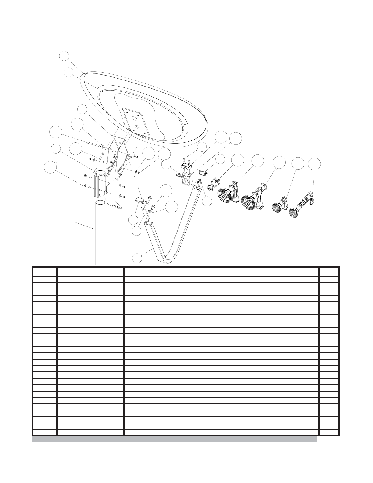
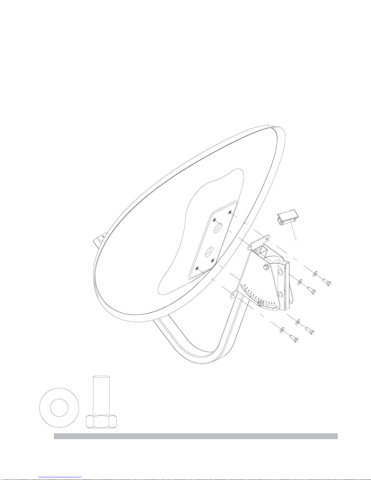
ThankyouforpurchasingyourPatriotCommercial Antenna. We trust that you will find this to be a
well designed product that will provide many years of reliable service. This manual covers the
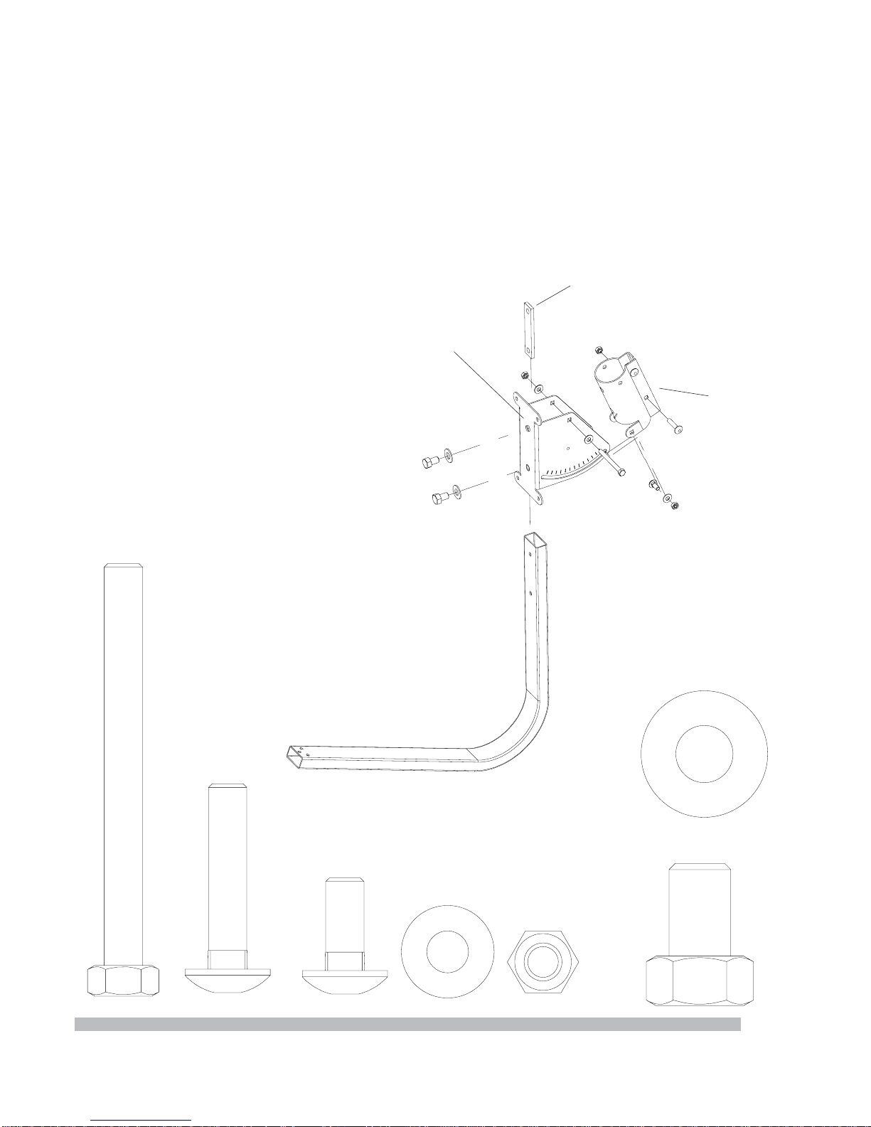
assembly and installation of the 75e Elliptical Antenna System. Read this manual thoroughly
before beginning assembly. For best results in the assembly process. Perform each step in the
same sequence as listed in this manual. Record the serial number of the unit on to page 2 for
futurereference andreadthe warrantyinformation.The serialnumbercan befoundon theantenna
back structure.
SITE SELECTION
The main objective of conducting a site survey utilizing a compass and inclinometer is to choose
amountinglocationon the ground that will give you thegreatestamountofswingforazimuth and
elevation for present as well as future use. A thorough preinstallation site survey is strongly rec-
ommended because it can alert you to any“look angle”, soil, wind or other problems.
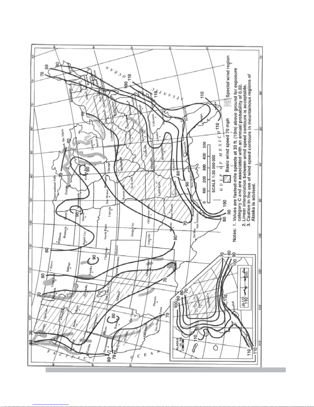
The first and most important consideration when choosing a prospective antenna site is whether
or not the area can provide an acceptable “look angle” to the satellite. A site with a clear, unob-
structed view facing south, southeast is required.Your antenna site must be selected in advance
so that you will be able to receive the strongest signal available. Also consider obstructions that
may occur in the future such as the growth of trees.
Itisimportanttoconductanon-sitesurveywithaportableantennaorwith a compass and clinom-
eter to avoid interference, obstructions, etc.
Whenselecting“look angle”,besuretoobserve and takereadingsapproximately10 deg totheleft
andright,aboveand below your selected “look angle”.
Before Ground Pole Installation, the soil type should be checked because soil conditions vary
widely in composition and load bearing capacity.A soil check will help you to determine the type
and size of foundation required to provide a stable base for the antenna.
Beforedigging isdone,informationregarding thepossibilityof undergroundtelephonelines,power
lines, storm drains, etc., in the excavation area should be obtained from the appropriate agency.
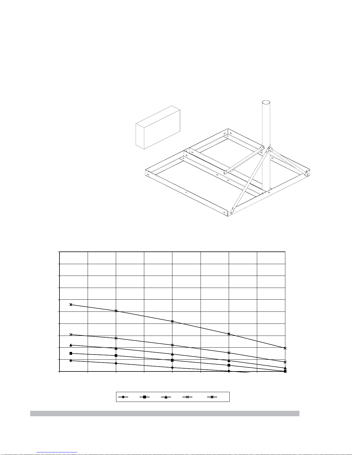
Aswithanyothertype of construction, a local building permit may be required before installingan
antenna.Itisthepropertyowner’sresponsibilitytoobtainanyandallpermits.Groundmountsare
certified for 125 mph wind survival.
4

5
ITEM QTY.
1
2
3
4
5
6
7
8
9
10
11
12
13
14
15
16
17
18
19
20
21
22
23
24
PART NO. DESCRIPTION 1
1
1
1
1
2
1
5
3
2
2
1
2
14
6
3
2
1
1
1
1
1
1
1
207501
207502
207503
207504
207505
1H075E HWD.KIT
207506
1H075E HWD. KIT
PE0400A
PE0400B
TXFD-KA/KUR
TXFD-OMTKUL
TXFD-DPLCOPOL/KUL
TXFD-OMTKAL
TXFD-OMTPLKA
Reflector,75cm Eliptical
1H075E HWD. KIT
1H075E HWD. KIT
1H075E HWD. KIT
1H075E HWD. KIT
1H075E HWD. KIT
1H075E HWD. KIT
1H075E HWD. KIT
Back Structure, 75cm Eliptical
Elevation Bracket
Pipe Adaptor
Feed Support
Plastic End Cap
1/2-13 Threaded Flat Bar
1/4-20 x 1 Soc. Cap Screw
1/4-20 Fin. Hex Nut
1/2-13 x 3/4 HCS, G-2
M8-1.25 x 40mm Car. Bolt, G-4.5
M8-1.25 x 80mm HCS, G-8.8
M8-1.25 x 25mm HCS, G-8.8
5/16 SAE Flat Washer
M8-1.25 Nyl. Inst. L/N
1/4 SAE Flat Washer
1/2 SAE Flat Washer
Feed Holder, Top
Feed Holder, Btm
Ku Rx only, Feed Assembly (Optional)
Ku Tx/Rx Xpol, Feed Assembly (Optional)
Ku Tx/Rx CoPol, Feed Assembly (Optional)
Ka Tx/Rx Linear Pol, Feed Assembly (Optional)
Ka Tx/Rx Circular Pol, Feed Assembly (Optional)
1
2
3
4
5
6
6
7
8
9
10
11
12
13 14 15
16
17
818 19
20 21 22 23 24
Mast
(notincluded)
1H075E HWD. KIT
1H075E HWD. KIT
Parts and Hardware

GroundingRodClamp&Grounding Block - As required by
National Electric Code or local codes.
GroundWire - #10 solid copper or asrequired byNational
Electric Code or local codes.
CoaxialCable(Size&Length required).
Concrete-(SeeGroundPolesectionbelow).
#3Rebar-(SeeGround Polesection below).Deformed
steel per ASTM A615, grade 40 or 60.
Preinstallation materials checklist
-Universal mount/wall mount #CHA-WALL 238/300 (optional) shown on cover.
Assembly tools required
1- 1/4”allenwrench (supplied)
1- 5/32”allenwrench
1- Combinationwrench-3/4”
2- Cominationwrenches-1/2”
1- Inclinometer (for sighting in)
1- Compass (for sighting in)
• Steel Mast: L=72”; 2-3/8” (60mm) O.D. Tubing Plumb within 1deg.
• Concrete: 3000 psi at 28 days, poured against undisturbed soil
(Allow concrete 24 hour set time before installation of antenna)
• Soil Bearing Capacity > 2000 psf.
• Ground the Antenna to meet applicable local Codes.
In-Ground Mast Foundation
6
40” min.
24” 18” min.
10”
Mast Pipe
2-3/8” O.D.
Anti-Twist Rebar
5/8” Diam. x 9”
Grade

Non-Penetrating Mount (optional)
1. Assemble the Non-Penetrating mount per the supplied instructions to provide the mast for
the mount installation.
Ballast Requirement Chart
75cm
100
200
300
400
500
600
700
800
900
1000
1100
20 25 30 35 40 45 50 55 60
Elevation Angle (deg)
Ballast (lbs)
70 80 90 100 125
Wind Speed (mph)
Patriot Antenna Systems
28 lb
NOTE:
Ifrequiredballast does not
fit the tray. Optional add-
on tray(s) must be added.
7
# NPM 238

*SPECIALWIND REGIONS:
Records or experience indicates that the wind speeds are higher in mountainous terrain, gorges, and ocean promontories and shall be examined
for unusual wind conditions. Contact your local meteorological authority and a local civil or professional engineer if your installation is in one of
these areas.
8

Assembly and installation
MountAssembly
1. Assemble the Feed Support Tube to the Elevation bracket as shown by sliding theThreaded
FlatBarinFeedSupportTube using 1/2” hardware represented below. Tighten this hardware.
2. Attach the Elevation Bracket to the Pipe Bracket. Partially tighten all this hardware at this
time.
B
C
1x
2x
2x
8x 5x
A
D
2x
9
A
C
B
D
Pipe
Bracket
Feed
Support
Tube
Elevation
Bracket
Threaded
Flat Bar
E
2x
E

ReflectorAssembly
1. AttachtheAntennaassembly tothe ElevationBracketsasshown using M8 hardware. Tighten
thishardware.
4x
4x
insert plug at
this time.
10

3.Insert plastic plug into end of feed support tube.
11
FeedAssembly
1. Attach the relevant Feed Assembly.
2. Insert the Feed Assembly into the Feed holder and assemble to the Feed Support Tube
usingthehardware illustrated below.
NOTE: 2 nuts slide into the back of the Feed Holder.
5x
5x
FeedHorn
Feed
Holder
Feed
Support
Tube
Tx
Port
Rx
Port
Plug
Refer to page 5 for more
information of Feed Assemblies.
Rx Port
Rx Port
Rx Port
Rx Port
Rx Port
Tx Port
Tx Port
Tx Port
Tx Port
24
23
22
21
20

Feed Adjustment (Polarity tuning)
1. Adjust the Feed to the appropriate skew angle
usingtheprovidedscalereference.
NOTE: Refer to the chart below for polarization
angle. Elevation and polarity are both dependent
on site azimuth and the difference between satel-
lite and site longitude.
NOTE: Some satellites have a slant angle with re-
spect to the satellite belt angle. Contact the satel-
liteoperator for details.
CW
CCW
Install site west Install site East
of satellite of satellite
CW CCW NorthernHemisphere
CCW CW SouthernHemisphere
FeedRotation Chart
LNB
BUC
Polarity
Scale
Reading
Points
NOTE:Linear Polarity systems only
12

Antenna Pointing
NOTE: The Reflector contains a 19 degree offset look angle. Therefore, when the reflector
aperture is perpendicular to the ground, the antenna is actually looking 19 degrees in elevation.
Elevation of Satellite above horizon = Measured angel from face of reflector plus 19.
1. Determine the elevation angle of the desired satellite, and rotate the elevation bracket to this
angle,andtightenhardwareto hold in place.
2. Azimuth Adjustment: With the electronics set to acquire the satellite, rotate the antenna in
azimuthuntil the satelliteisfound.Roughly obtain thestrongestsignaland tighten thehardwareon
the Pipe Bracket.
NOTE: If signal is not found on first pass of Azimuth, adjust elevation up or down in 2 deg.
increments until signal is found.
3. Peakthesatellitesignalbyfine
adjustmentsmadeinboth azimuth
and elevation until the optimum
signal is achieved.
4. Tightenallmount hardware.
13
Elevation
Adjustment
Scale
5. Patriot recommends the use of cross pol nulling using a spectrum analyzer during Tx/Rx
installations. After tightening the azimuth and elevation hardware, peak the co-pol signal using
the spectrum analyzer. Then rotate the feed assembly roughly 90 degrees to obtain a cross pol
null.Fine tune the null. Thescaleon the feed horn canbeused with the tick mark onfeedholder
toportheseambetweenfeedholdertopandbottom.The tick mark and seam are 90 deg. a part.
Note that changes may be necessary to the resolution and video bandwidth to bring the signal
above the noise floor. Note the angle of optimum cross pol null. Rotate the feed back exactly 90
degreesandtighten the feed clamp.
NOTE:For Rx only, Installation is complete.ForTx/Rx Installation, continue to step 5.

External
Toothed
Washer
Grounding
Grounding Antenna Feed Cables
1. Ground antenna feed cables in
accordance with current National
Electric code and local electric
codes. The illustration shows a
typicalgroundingmethod.
Clampsthatprovideasolidconnec-
tion between ground wire and a
groundsourceshouldbeused.
Grounding Non-Penetrating
Mount Frame (if applicable)
1. Ground the Non-Penetrating
mount frame. The illustration
showsatypicalgroundingmethod.
RefertotheNECSection810 and
local electric codes for specific in-
structionsongroundingtheremain-
ingendofthe ground wire.
Coaxial
Cable
(to LNB)
Ground Block
NEC Section 810
Ground Wire
NEC Section 810
Non-Pen
Frame
Ground
Lug
1/4” Tapping
Bolt
14

15
Equipment From The Industry’s Lead-
ing Satellite Equipment
Manufacturer’s
Available Together - In One Place...
WeareCal-Amp’sLARGEST
STOCKINGDISTRIBUTOR!
NoLongLead Times...
No Drop Ship Fees...
HighInventory...
Great Prices...
Complete line of Quality Feedhorns,
Receivers and Accessories - from a
name you trust
W e A l s o O f f e r P r o d u c t s f r o m t h e f o l l o w i n g :
Durable Snow Covers for Commercial
Antennas as well as Home System -
Keep snow from interfering with your
signal.
Prevent Snow & Ice from accumlulating
on your system with a De-Icing System. Complete line of Antenna Controllers,
Positioners and Software for your
motorized applications.
Looking to increase your
satellite’s reception? Try
upgrading your feed
system to a Multi-Beam
Feed. Receive up to 4
simultaneous satellites
Products Also Avaliable from:
Offset VSAT
& DBS Antennas Available!
•
ADL• General Instruments
• Baird • Norsat
• Drake • Standard Comm
• DX • Thomson-Saginaw
• Force • Wegner
Toll Free 1-800-470-3510

ANTENNA SYSTEMS
704 North Clark Street
Albion, MI 49224 USA
Tel: (517)629-5990
Fax: (517)629-6690
E-mail: [email protected]
Web site: www.sepatriot.com
Specifications
Part# 2M07590 Rev-10-13-03
Electrical
Tx Band
RxBand
TxGain(Midband)
RxGain (Midband)
Efficiency
SideLobes
CrossPolarization(on axis)
Ku-Band
13.75 - 14.50
10.70-12.75
39.4 dBi
37.7 dBi
70%
ITU - 580 -5
>35dB
Ka-Band
29.50-30.00
19.70-20.20
45.5 dBi
42.0 dBi
65%
Mechanical
AntennaSize 75cm (29.5”)
Offset Angle 19degrees
F/D 0.60
OperationalWind 50mph
SurvivalWind 125mph
OperationalTemp -40 to 140 F
SurvivalTemp -60 to 180 F
Rain Operational= 1/2in./hr
Survival = 3in./hr
Ice 1in.Radial -or-
1/2 in. + 60mph wind
Pole Size 2-3/8”OD
Table of contents
Other Patriot Antenna manuals

Patriot
Patriot 1.0M User manual

Patriot
Patriot Commercial Antenna Polar Mount User manual

Patriot
Patriot Patriot 3.8m Commercial Antenna King Post... User manual

Patriot
Patriot PRT-240M NAV User manual

Patriot
Patriot 2.4m Offset Antenna User manual

Patriot
Patriot 1.2M MVSAT Guide

Patriot
Patriot 1.0M User manual