Pattfield Ergo Tools E-AS 18-evo User manual

kBedienungsanleitung
Akku-Bohrschrauber
tOperating Instructions
Cordless Drill
pMode d’emploi
Perceuse-visseuse sans fil
CIstruzioni per l’uso
Trapano avvitatore a batteria
NHandleiding
Accuboorschroefmachine
UBruksanvisning
Batteridriven borrmaskin/skruvdragare
jNávod k obsluze
Akumulátorový vrtací šroubovák
Instrucøiuni de folosire
Maμinå electronicå de gåurit μi înμurubat
cu acumulator cu reglarea momentului de
rotaøie
WNávod na obsluhu
Akumulátorový vŕtací skrutkovač
Art.-Nr.: 44.720.80 I.-Nr.: 01027 E-AS 18-evo
Anleitung_E_AS_18evo_SPK7:_ 04.01.2008 11:29 Uhr Seite 1

2
kUm eine Beschädigung des Getriebes zu vermeiden, darf die Gangumschaltung nur im
Stillstand umgeschaltet werden
tChange the gear only when the drill is at a standstill. If you fail to observe this point, the
gearing may be damaged.
pAfin d’évider d’endommager l’engrenage, les vitesses doivent être uniquement
commutées à l’arrêt.
CPer evitare danni al meccanismo, la commutazione di marcia può venire cambiata solo
ad utensile fermo.
NOm een beschadiging van de transmissie te voorkomen mag de versnellingsschakeling
enkel in stilstand worden omgeschakeld.
UFör att undvika att maskinens växel förstörs, får du endast växla medan maskinen står
stilla.
jAby se zabránilo poškození převodovky, smí být přepínání směru otáčení prováděno
pouze ve vypnutém stavu.
QPentru a evita deteriorarea transmisiei, comutarea vitezei se va realiza numai atunci când
aparatul este în repaus.
WAby sa zabránilo poškodeniu prevodovky, smú sa prepínať otáčkové stupne iba vtedy, keď
je prístroj v stave pokoja.
Anleitung_E_AS_18evo_SPK7:_ 04.01.2008 11:29 Uhr Seite 2

3
1
21
6
9
2 3
4
1.
2.
5
6
8
1.
5
8
7
3
5
Anleitung_E_AS_18evo_SPK7:_ 04.01.2008 11:29 Uhr Seite 3

4
4
1
5
4
6
3
7
1
2
7a2
Anleitung_E_AS_18evo_SPK7:_ 04.01.2008 11:29 Uhr Seite 4

5
D
“WARNUNG - Zur Verringerung des Verletzungsrisikos Bedienungsanleitung lesen”
Tragen Sie einen Gehörschutz.
Die Einwirkung von Lärm kann Gehörverlust bewirken.
Tragen Sie eine Staubschutzmaske.
Beim Bearbeiten von Holz und anderer Materialien kann gesundheitsschädlicher Staub
entstehen. Asbesthaltiges Material darf nicht bearbeitet werden!
Tragen Sie eine Schutzbrille.
Während der Arbeit entstehende Funken oder aus dem Gerät heraustretende Splitter, Späne
und Stäube können Sichtverlust bewirken.
Anleitung_E_AS_18evo_SPK7:_ 04.01.2008 11:29 Uhr Seite 5

6
D
Achtung!
Beim Benutzen von Geräten müssen einige
Sicherheitsvorkehrungen eingehalten werden, um
Verletzungen und Schäden zu verhindern. Lesen Sie
diese Bedienungsanleitung / Sicherheitshinweise
deshalb sorgfältig durch. Bewahren Sie diese gut auf,
damit Ihnen die Informationen jederzeit zur
Verfügung stehen. Falls Sie das Gerät an andere
Personen übergeben sollten, händigen Sie diese
Bedienungsanleitung / Sicherheitshinweise bitte mit
aus. Wir übernehmen keine Haftung für Unfälle oder
Schäden, die durch Nichtbeachten dieser Anleitung
und den Sicherheitshinweisen entstehen.
1. Sicherheitshinweise
Die entsprechenden Sicherheitshinweise finden Sie
im beiliegenden Heftchen!
WARNUNG
Lesen Sie alle Sicherheitshinweise und
Anweisungen. Versäumnisse bei der Einhaltung der
Sicherheitshinweise und Anweisungen können
elektrischen Schlag, Brand und/oder schwere
Verletzungen verursachen zur Folge haben.
Bewahren Sie alle Sicherheitshinweise und
Anweisungen für die Zukunft auf.
2. Gerätebeschreibung (Abb. 1)
1. Drehmomenteinstellung
2. Schnellspannbohrfutter
3. Drehrichtungsschalter
4. Ein-/ Ausschalter
5. Akku
6. Ladegerät
7. Umschalter 1. Gang - 2. Gang
8. Rasttaste
9. Bithalterung
3. Bestimmungsgemäße Verwendung
Der Akku-Bohrschrauber ist geeignet zum Eindrehen
und Lösen von Schrauben, sowie zum Bohren in
Holz, Metall und Kunststoff.
Das Gerät darf nur nach ihrer Bestimmung
verwendet werden. Jede weitere darüber
hinausgehende Verwendung ist nicht
bestimmungsgemäß. Für daraus hervorgerufene
Schäden oder Verletzungen aller Art haftet der
Benutzer/Bediener und nicht der Hersteller.
Bitte beachten Sie, dass unsere Geräte
bestimmungsgemäß nicht für den gewerblichen,
handwerklichen oder industriellen Einsatz konstruiert
wurden. Wir übernehmen keine Gewährleistung,
wenn das Gerät in Gewerbe-, Handwerks- oder
Industriebetrieben sowie bei gleichzusetzenden
Tätigkeiten eingesetzt wird.
4. Technische Daten
Spannungsversorgung Motor: 18 V d.c.
Leerlauf-Drehnzahl: 0-350/0-900 min-1
Drehmomentstufen: 16+1
Rechts- Links-Lauf: ja
Spannweite Bohrfutter: max. 10 mm
Ladespannung Akku: 18 V d.c.
Ladestrom Akku: 2,5 A
Netzspannung Ladegerät: 230V~ 50Hz
Ladezeit: max. 1 Std.
Akkutyp: NiCd
Gewicht: 1,75 kg
Geräusch und Vibration
Die Geräusch- und Vibrationswerte wurden entspre-
chend EN 60745 ermittelt.
Schalldruckpegel LpA 69 dB(A)
Unsicherheit KpA 3 dB
Schallleistungspegel LWA 80 dB(A)
Unsicherheit KWA 3 dB
Tragen Sie einen Gehörschutz.
Die Einwirkung von Lärm kann Gehörverlust bewir-
ken.
Schwingungsgesamtwerte (Vektorsumme dreier
Richtungen) ermittelt entsprechend EN 60745.
Bohren in Metall
Schwingungsemissionswert ah≤2,5 m/s2
Unsicherheit K = 1,5 m/s2
Schrauben ohne Schlag
Schwingungsemissionswert ah≤2,5 m/s2
Unsicherheit K = 1,5 m/s2
Anleitung_E_AS_18evo_SPK7:_ 04.01.2008 11:29 Uhr Seite 6

7
D
Achtung!
Der Schwingungswert wird sich aufgrund des Ein-
satzbereiches des Elektrowerkzeuges ändern und
kann in Ausnahmefällen über dem angegebenen
Wert liegen.
5. Vor Inbetriebnahme
Lesen Sie vor der Inbetriebnahme Ihres
Akkuschraubers unbedingt diese Hinweise:
1. Laden Sie den Akku-Pack nur mit dem
mitgelieferten Ladegerät.
2. Nur scharfe Bohrer sowie einwandfreie und
geeignete Schrauberbits verwenden.
3. Beim Bohren und Schrauben in Wänden und
Mauern diese auf verborgene Strom-, Gas- und
Wasserleitung überprüfen.
6. Bedienung
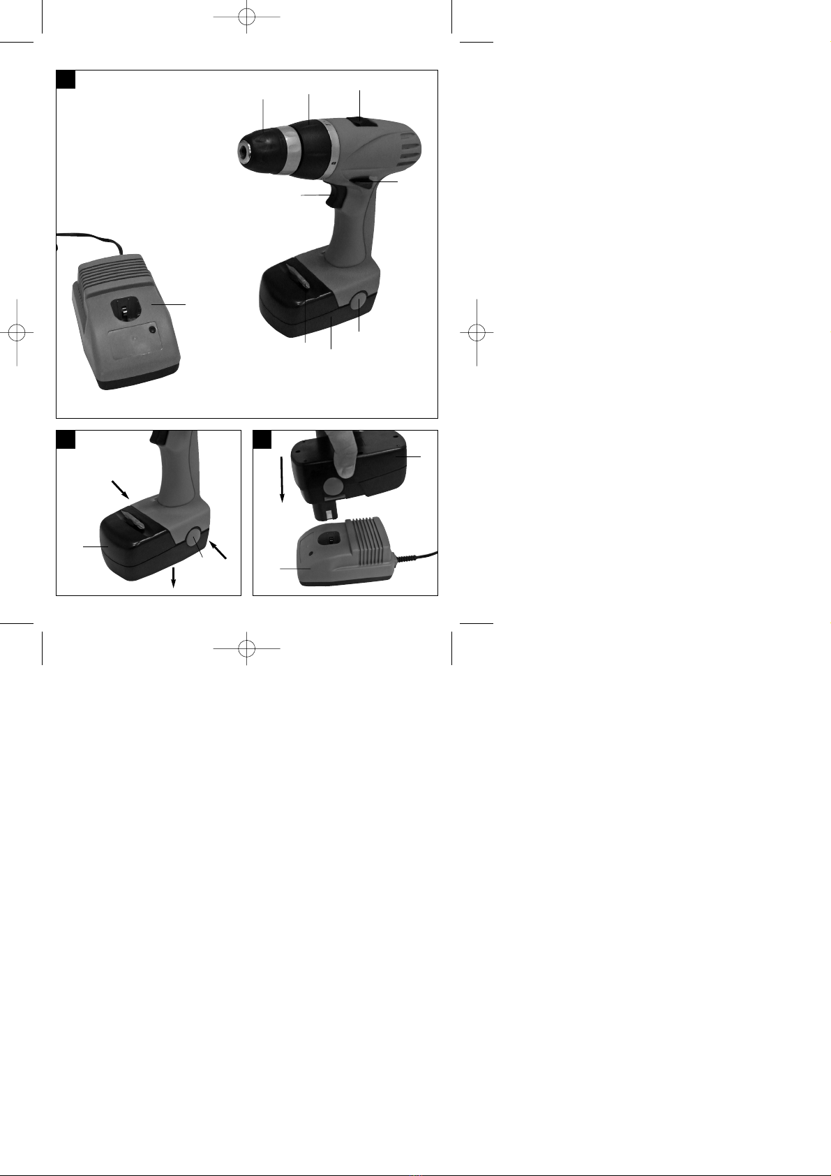
6.1 Laden des Akkus (Abb. 2-3)
1. Akku-Pack aus dem Handgriff heraus ziehen
(Bild 2), dabei die Rasttasten drücken.
2. Vergleichen Sie, ob die auf dem Typenschild
angegebene Netzspannung mit der vorhandenen
Netzspannung übereinstimmt. Stecken Sie das
Ladegerät in die Steckdose.
3. Die LED leuchtet grün. Stecken Sie den Akku in
das Ladegerät. Die LED leuchtet nun rot. Dies
signalisiert, dass der Akku geladen wird. Wenn
der Ladevorgang nach ca. 1 Stunde beendet ist,
leuchtet die LED wieder grün. Während des
Ladevorgangs kann sich der Akku-Pack
erwärmen, dies ist jedoch normal.
Sollte das Laden des Akku-Packs nicht möglich sein,
überprüfen Sie bitte
ob an der Steckdose die Netzspannung
vorhanden ist.
ob ein einwandfreier Kontakt an den
Ladekontakten des Ladegerätes vorhanden ist.
Sollte das Laden des Akku-Packs immer noch nicht
möglich sein, bitten wir Sie,
das Ladegerät
und den Akku-Pack
an unseren Kundendienst zu senden.
Im Interesse einer langen Lebensdauer des Akku-
Packs sollten Sie für eine rechtzeitige
Wiederaufladung des Akku-Packs sorgen. Dies ist
auf jeden Fall notwendig, wenn Sie feststellen, dass
die Leistung des Akku-Schraubers nachlässt.
Entladen Sie den Akku-Pack nie vollständig. Dies
führt zu einem Defekt des Akku-Packs!
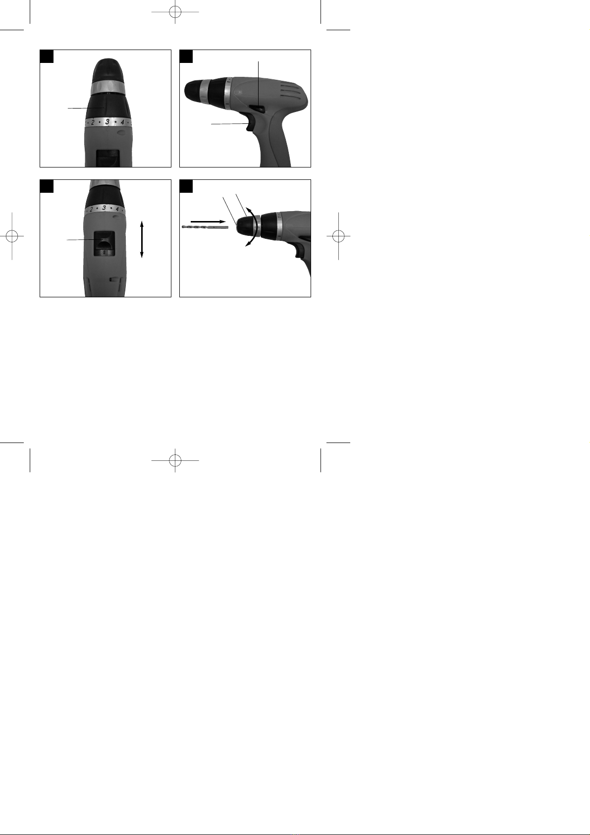
6.2 Drehmoment-Einstellung (Abb. 4/Pos. 1)
Der Akkuschrauber ist mit einer mechanischen
Drehmomenteinstellung ausgestattet.
Das Drehmoment für eine bestimmte
Schraubengröße wird am Stellring (1) eingestellt.
Das Drehmoment ist von mehreren Faktoren
abhängig:
von der Art und Härte des zu bearbeitenden
Materials.
von der Art und der Länge der verwendeten
Schrauben.
von den Anforderungen, die an die
Schraubverbindung gestellt werden.
Das Erreichen des Drehmoments wird durch das
ratschende Ausrücken der Kupplung signalisiert.
Achtung! Stellring für das Drehmoment nur bei
Stillstand einstellen.
6.3 Bohren (Abb. 4/Pos. 1)
Zum Bohren stellen Sie den Einstellring für das
Drehmoment auf die letzte Stufe „Bohrer“. In der
Stufe Bohren ist die Rutschkupplung außer Betrieb.
Beim Bohren ist das maximale Drehmoment
verfügbar.
6.4 Drehrichtungsschalter (Abb. 5/Pos. 3)
Mit dem Schiebeschalter über dem Ein/Aus-Schalter
können Sie die Drehrichtung des Akku-Schraubers
einstellen und den Akku-Schrauber gegen
ungewolltes Einschalten sichern. Sie können
zwischen Links- und Rechtslauf wählen. Um eine
Beschädigung des Getriebes zu vermeiden, darf die
Drehrichtung nur im Stillstand umgeschaltet werden.
Befindet sich der Schiebeschalter in der
Mittelstellung, ist der Ein/Aus-Schalter blockiert.
6.5 Ein/Aus-Schalter (Abb. 5/Pos. 4)
Mit dem Ein/Aus-Schalter können Sie die Drehzahl
stufenlos steuern. Je weiter Sie den Schalter
drücken, desto höher ist die Drehzahl des
Akkuschraubers.
6.6 Umschaltung Gang 1 - Gang 2 (Abb. 6/Pos. 7)
Je nach Stellung des Umschalters können Sie mit
einer höheren oder niedrigeren Drehzahl arbeiten.
Um eine Beschädigung des Getriebes zu vermeiden,
darf die Gangumschaltung nur im Stillstand
umgeschaltet werden.
Anleitung_E_AS_18evo_SPK7:_ 04.01.2008 11:29 Uhr Seite 7

8
D
6.7 Werkzeugwechsel (Bild 7)
Achtung! Stellen Sie bei allen Arbeiten (z.B.
Werkzeugwechsel; Wartung; usw.) am
Akkuschrauber den Drehrichtungsschalter (3) in
Mittelstellung.
Der Akkuschrauber ist mit einem
Schnellspanbohrfutter (2) mit automatischer
Spindelarretierung ausgestattet.
Drehen Sie das Bohrfutter (2) auf.
Die Bohrfutteröffnung (a) muss groß genug sein,
um das Werkzeug (Bohrer bzw. Schrauberbit)
aufzunehmen.
Wählen Sie das geeignete Werkzeug aus.
Schieben Sie das Werkzeug soweit wie möglich
in die Bohrfutteröffnung (a) hinein.
Drehen Sie das Bohrfutter (2) fest zu, und prüfen
Sie anschließend den festen Sitz des
Werkzeuges.
6.8 Schrauben
Verwenden Sie am besten Schrauben mit
Selbstzentrierung (z. B. Torx, Kreuzschiltz), welches
ein sicheres Arbeiten gewährleistet. Achten Sie
darauf, dass der verwendete Bit und die Schraube in
Form und Größe übereinstimmen. Nehmen Sie die
Drehmomenteinstellung, wie in der Anleitung
beschrieben, entsprechend der Schraubengröße vor.
7. Reinigung, Wartung und
Ersatzteilbestellung
Ziehen Sie vor allen Reinigungsarbeiten den
Netzstecker.
7.1 Reinigung
Halten Sie Schutzvorrichtungen, Luftschlitze und
Motorengehäuse so staub- und schmutzfrei wie
möglich. Reiben Sie das Gerät mit einem
sauberen Tuch ab oder blasen Sie es mit
Druckluft bei niedrigem Druck aus.
Wir empfehlen, dass Sie das Gerät direkt nach
jeder Benutzung reinigen.
Reinigen Sie das Gerät regelmäßig mit einem
feuchten Tuch und etwas Schmierseife.
Verwenden Sie keine Reinigungs- oder
Lösungsmittel; diese könnten die Kunststoffteile
des Gerätes angreifen. Achten Sie darauf, dass
kein Wasser in das Geräteinnere gelangen kann.
7.2 Wartung
Im Geräteinneren befinden sich keine weiteren
zu wartenden Teile.
7.3 Ersatzteilbestellung:
Bei der Ersatzteilbestellung sollten folgende
Angaben gemacht werden;
Typ des Gerätes
Artikelnummer des Gerätes
Ident-Nummer des Gerätes
Ersatzteilnummer des erforderlichen Ersatzteils
Aktuelle Preise und Infos finden Sie unter
www.isc-gmbh.info
8. Entsorgung und Wiederverwertung
Das Gerät befindet sich in einer Verpackung um
Transportschäden zu verhindern. Diese Verpackung
ist Rohstoff und ist somit wieder verwendbar oder
kann dem Rohstoffkreislauf zurückgeführt werden.
Das Gerät und dessen Zubehör bestehen aus
verschiedenen Materialien, wie z.B. Metall und
Kunststoffe. Führen Sie defekte Bauteile der
Sondermüllentsorgung zu. Fragen Sie im
Fachgeschäft oder in der Gemeindeverwaltung nach!
Anleitung_E_AS_18evo_SPK7:_ 04.01.2008 11:29 Uhr Seite 8

9
GB
“Caution - Read the operating instructions to reduce the risk of inquiry”
Wear ear-muffs.
The impact of noise can cause damage to hearing.
Wear a breathing mask.
Dust which is injurious to health can be generated when working on wood and other materials.
Never use the device to work on any materials containing asbestos!
Wear safety goggles.
Sparks generated during working or splinters, chips and dust emitted by the device can cause
loss of sight.
Anleitung_E_AS_18evo_SPK7:_ 04.01.2008 11:29 Uhr Seite 9

Important!
When using equipment, a few safety precautions
must be observed to avoid injuries and damage.
Please read the complete operating manual with due
care. Keep this manual in a safe place, so that the
information is available at all times. If you give the
equipment to any other person, give them these
operating instructions as well.
We accept no liability for damage or accidents which
arise due to non-observance of these instructions
and the safety information.
1. Safety information
Please refer to the booklet included in delivery for the
safety instructions.
CAUTION!
Read all safety regulations and instructions.
Any errors made in following the safety regulations
and instructions may result in an electric shock, fire
and/or serious injury.
Keep all safety regulations and instructions in a
safe place for future use.
2. Layout (Fig. 1)
1. Torque selector
2. Quick-change drill chuck
3. Changeover switch
4. ON/OFF switch
5. Battery pack
6. Battery charger
7. Selector switch for 1st/2nd gear
8. Pushlock button
9. Bit holder
3. Proper use
The cordless drill/screwdriver is designed for
tightening and undoing screws, as well as for drilling
in wood, metal and plastic.
The machine is to be used only for its prescribed
purpose. Any other use is deemed to be a case of
misuse. The user / operator and not the
manufacturer will be liable for any damage or injuries
of any kind caused as a result of this.
Please note that our equipment has not been
designed for use in commercial, trade or industrial
applications. Our warranty will be voided if the
machine is used in commercial, trade or industrial
businesses or for equivalent purposes.
4. Technical data
Voltage supply 18 V d.c.
Idling speed: 0-350/0-900 rpm
Torque settings: 16+1
Forward and reverse rotation yes
Chuck clamping width max. 10 mm
Battery charging voltage 18 V d.c.
Battery charging current 2.5 A
Mains voltage for charger 230 V ~ 50 Hz
Charging time: max. 1 hours
Battery type: NiCd
Weight 1.75 kg
Sound and vibration
Sound and vibration values were measured in
accordance with EN 60745.
LpA sound pressure level 69 dB(A)
KpA uncertainty 3 dB
LWA sound power level 80 dB(A)
KWA uncertainty 3 dB
Wear ear-muffs.
The impact of noise can cause damage to hearing.
Total vibration values (vector sum of three directions)
determined in accordance with EN 60745.
Drilling in concrete
Vibration emission value ah≤2,5 m/s2
K uncertainty = 1,5 m/s2
Screwing without hammer action
Vibration emission value ah≤2,5 m/s2
K uncertainty = 1,5 m/s2
Important!
The vibration value changes according to the area of
application of the electric tool and may exceed the
specified value in exceptional circumstances.
GB
10
Anleitung_E_AS_18evo_SPK7:_ 04.01.2008 11:29 Uhr Seite 10

5. Before starting the equipment
Be sure to read the following information before you
use your cordless screwdriver for the first time:
1. Charge the battery pack only with the charger
supplied.
2. Only ever use sharp drill bits and screwdriver bits
which are suitable for the purpose and in
faultless condition.
3. Always check for concealed electric cables and
gas and water pipes when drilling and screwing
in walls.
6. Operation
6.1 Charging the LI battery pack (Fig. 2/3)
1. Take the rechargeable battery pack out of the
handle (Fig. 2), pressing the pushlock buttons at
the side to do so.
2. Check that your mains voltage is the same as that
marked on the rating plate of the battery charger.
Plug the battery charger in the socket.
3. The green LED will come on. Insert the battery
pack in the battery charger. Now the rot LED will
come on to indicate that the battery pack is being
charged. When the charging period is completed
after approx. 1 hour, the green LED will come on
again. The temperature of the battery pack may
rise during the charging operation. This is
normal.
If the battery pack fails to become charged, please
check
whether there is voltage at the socket-outlet
whether there is proper contact at the charging
contacts on the charger.
If the battery still fails to become charged, please
return
the charger
the battery pack
to our Customer Service Department.
To ensure that the battery pack provides long service,
you should take care to recharge it promptly. You
must recharge the battery pack when you notice that
the power of the cordless screwdriver drops.
Never fully discharge the battery pack. This will cause
it to develop a defect!
6.2 Torque setting (Fig. 4 / Item 1)
The cordless screwdriver is fitted with a mechanical
torque selector.
The torque for a specific size of screw is selected
with the set-collar (1). The correct torque depends on
several factors:
on the type and hardness of material in question
on the type and length screws used
on the requirements needing to be met by the
screwed joint.
The clutch disengages with a grating sound to
indicate when the set torque is reached.
Important! The tool must be at a standstill when
you set the torque with the setting ring.
6.3 Drilling (Fig. 4 / Item 1)
For drilling purposes, move the set-collar to the last
step „Drill“. In this setting the slip clutch is inactive.
The maximum torque is available in drilling mode.
6.4 Forward/Reverse switch (Fig. 5 / Item 3)
With the slide switch above the On/Off switch you
can select the direction of rotation of the battery-
powered drill/screwdriver and secure it against being
switched on accidentally. You can choose between
clockwise and anticlockwise rotation. To avoid
causing damage to the gearing it is advisable to
change the direction of rotation only when the tool is
at a standstill. The On/Off switch is blocked when the
slide switch is in centre position.
6.5 On/Off switch (Fig. 5 / Item 4)
Infinitely variable speed control is possible with the
On/Off switch. The further you press the switch, the
higher the speed of the battery-powered
drill/screwdriver.
6.6 Changing over from 1st gear to 2nd gear
(Fig. 6 / Item 7)
You can work at a higher or lower speed depending
on the position of the selector switch. To avoid
damaging the gear unit you should only change over
gears when the tool has stopped.
6.7 Changing the tool (Fig. 7)
Important. Set the changeover switch (3) to its
centre position whenever you carry out any work (for
example changing the tool, maintenance work, etc.)
on the cordless screwdriver.
The cordless screwdriver is fitted with a quick-
action chuck (2) with an automatic spindle stop.
Open the chuck (2). The chuck opening (a) must
be large enough to hold the tool (drill bit or
GB
11
Anleitung_E_AS_18evo_SPK7:_ 04.01.2008 11:29 Uhr Seite 11

screwdriver bit).
Select the suitable tool. Push the tool as far as
possible into the chuck opening (a).
Tighten the chuck (2) and then check that the
tool is secure.
6.8 Screwdriving
We recommend using self-centering screws (e.g.
Torx screws, recessed head screws) designed for
reliable working. Be sure to use a bit that matches
the screw in shape and size. Set the torque, as
described elsewhere in these operating instructions,
to suit the size of screw.
7. Cleaning, maintenance and ordering
of spare parts
Always pull out the mains power plug before starting
any cleaning work.
7.1 Cleaning
Keep all safety devices, air vents and the motor
housing free of dirt and dust as far as possible.
Wipe the equipment with a clean cloth or blow it
with compressed air at low pressure.
We recommend that you clean the device
immediately each time you have finished using it.
Clean the equipment regularly with a moist cloth
and some soft soap. Do not use cleaning agents
or solvents; these could attack the plastic parts
of the equipment. Ensure that no water can seep
into the device.
7.2 Maintenance
There are no parts inside the equipment which
require additional maintenance.
7.3 Ordering replacement parts
Please quote the following data when ordering
replacement parts:
Type of machine
Article number of the machine
Identification number of the machine
Replacement part number of the part required
For our latest prices and information please go to
www.isc-gmbh.info
8. Disposal and recycling
The unit is supplied in packaging to prevent its being
damaged in transit. This packaging is raw material
and can therefore be reused or can be returned to
the raw material system.
The unit and its accessories are made of various
types of material, such as metal and plastic.
Defective components must be disposed of as
special waste. Ask your dealer or your local council.
GB
12
Anleitung_E_AS_18evo_SPK7:_ 04.01.2008 11:29 Uhr Seite 12

F
« Avertissement – Lisez ce mode d’emploi pour diminuer le risque de blessures »
Portez une protection de l’ouïe.
L’exposition au bruit peut entraîner une perte de l’ouïe.
Portez un masque anti-poussière.
Lors de travaux sur su bois et autres matériaux, de la poussière nuisible à la santé peut être
dégagée. Ne travaillez pas sur du matériau contenant de l’amiante !
Portez des lunettes de protection.
Les étincelles générées pendant travail ou les éclats, copeaux et la poussière sortant de
l’appareil peuvent entraîner une perte de la vue.
13
Anleitung_E_AS_18evo_SPK7:_ 04.01.2008 11:29 Uhr Seite 13

Attention !
Lors de l’utilisation d’appareils, il faut respecter
certaines mesures de sécurité afin d’éviter des
blessures et dommages. Veuillez donc lire
attentivement ce mode d’emploi. Conservez-le bien
de façon à pouvoir disposer à tout moment de ces
informations. Si l’appareil doit être remis à d’autres
personnes, remettez-leur aussi ce mode d’emploi.
Nous déclinons toute responsabilité pour les
accidents et dommages dus au non-respect de ce
mode d’emploi et des consignes de sécurité.
1. Consignes de sécurité
Vous trouverez les consignes de sécurité
correspondantes dans le petit manuel ci-joint.
AVERTISSEMENT !
Veuillez lire toutes les consignes de sécurité et
instructions.
Tout non-respect des consignes de sécurité et
instructions peut provoquer une décharge électrique,
un incendie et/ou des blessures graves.
Conservez toutes les consignes de sécurité et
instructions pour une consultation ultérieure.
2. Description de l’appareil (fig. 1)
1. Réglage du couple de serrage
2. Mandrin à serrage rapide
3. Interrupteur de sens de rotation
4. Interrupteurs marche/arrêt
5. Accumulateur
6. Chargeur
7. Commutateur 1e vitesse – 2e vitesse
8. Touche à cran
9. Porte-bits
3. Utilisation conforme à l’affectation
La vis-perceuse à accumulateur convient à visser et à
dévisser des vis tout comme au perçage dans le bois,
le métal et les matières plastiques.
La machine doit exclusivement être employée
conformément à son affectation. Chaque utilisation
allant au-delà de cette affectation est considérée
comme non conforme. Pour les dommages en
résultant ou les blessures de tout genre, le
producteur décline toute responsabilité et
l’opérateur/l’exploitant est responsable.
Veillez au fait que nos appareils, conformément à
leur affectation, n’ont pas été construits, pour être
utilisés dans un environnement professionnel,
industriel ou artisanal. Nous déclinons toute
responsabilité si l’appareil est utilisé
professionnellement, artisanalement ou dans des
sociétés industrielles, tout comme pour toute activité
équivalente.
4. Caractéristiques techniques
Alimentation en courant, moteur 18 V d.c.
Vitesse de rotation de
marche à vide : 0-350 / 0-900 tr/min
Niveau de couple de rotation : 16+1
Rotation vers la droite et vers la gauche oui
Capacité du serrage du mandrin max 10 mm
Tension de charge, accumulateur 18 V d.c.
Courant de charge, accumulateur 2,5 A
Tension secteur, chargeur 230 V ~ 50 Hz
Durée de charge : maxi. 1 h
Type d’accu : NiCd
Poids 1,75 kg
Bruit et vibration
Les valeurs de bruit et de vibration ont été
déterminées conformément à la norme EN 60745.
Niveau de pression acoustique LpA 69 dB(A)
Imprécision KpA 3 dB
Niveau de puissance acoustique LWA 80 dB(A)
Imprécision KWA 3 dB
Portez une protection acoustique.
L’exposition au bruit peut entraîner la perte de l’ouïe.
Les valeurs totales des vibrations (somme des
vecteurs de trois directions) ont été déterminées
conformément à EN 60745.
Percer le métal
Valeur d’émission des vibrations ah≤2,5 m/s2
Imprécision K = 1,5 m/s2
Visser sans percussion
Valeur d’émission des vibrations ah≤2,5 m/s2
Imprécision K = 1,5 m/s2
F
14
Anleitung_E_AS_18evo_SPK7:_ 04.01.2008 11:29 Uhr Seite 14

Attention !
La valeur de vibration est différente en fonction du
domaine d’utilisation de l’outil électrique et peut,
dans des cas exceptionnels, être supérieure à la
valeur indiquée.
5. Avant la mise en service
Avant la mise en service de votre tournevis
électrique sans fil, lisez ces remarques :
1. Chargez le bloc accumulateur uniquement avec
le chargeur fourni avec la livraison.
2. Utilisez uniquement des forets pointus tout
comme des embouts de tournevis irréprochables
et adéquats.
3. Lors du perçage et du vissage dans des parois
et murs, contr lez s’il y a des conduites de
courant, de gaz ou d’eau cachées.
6. Commande
6.1 Charger l’accumulateur (fig. 2-3)
1. Retirez le bloc accumulateur de la poignée (figure
2), ce faisant, pressez les touches à cran
latérales.
2. Comparez si la tension du secteur indiquée sur la
plaque signalétique correspond à la tension du
bloc du serveur disponible. Enfichez le chargeur
dans la prise.
3. La DEL s’allume en vert. Enfichez l’accumulateur
dans le chargeur. La DEL s’allume à présent en
rouge. Ceci signale que accumulateur est en
cours de chargement. Lorsque le processus de
chargement est terminé, au bout d’environ une
heure, la DEL se rallume en vert. Un léger
réchauffement de l’accumulateur peut avoir lieu
pendant le chargement. Ce phénomène est tout
à fait normal.
Si la charge du paquet accumulateur n’est pas
possible, vérifiez
que la prise de courant est sous tension
que les contacts du chargeur sont fiables.
S’il n’est toujours pas possible de charger le paquet
accumulateur, nous vous prions d’envoyer
le chargeur
et le paquet accumulateur
à notre station de service après-vente.
Dans l’intérêt d’une longue durée de vie du bloc
accumulateur, vous devez prendre soin de recharger
le bloc accumulateur en temps voulu. Ceci est de
toute manière nécessaire, lorsque vous constatez
que la puissance du tournevis sans fil diminue.
Ne déchargez jamais complètement le bloc
accumulateur. Ceci cause l’endommagement du bloc
accumulateur !
6.2 Réglage du couple de rotation (fig. 4/pos. 1)
Le tournevis sans fil est doté d’un réglage
mécanique du couple de rotation.
Le couple de rotation pour une taille définie de vis
est réglable par la molette de réglage (1). Le couple
de rotation dépend de plusieurs facteurs:
de la sorte et dureté du matériau à traiter
de la sorte et longueur des vis utilisées
des exigences auxquelles doivent répondre les
unions vissées
Si le couple de rotation est atteint, un grincement
indique que le désaccouplement est effectué.
Attention ! Ne réglez la bague de réglage pour le
couple de serrage qu’à l’arrêt de la machine.
6.3 Perçage (fig. 4/pos. 1)
Pour pouvoir percer, mettez la molette de réglage
pour le couple de rotation sur le dernier gradin
“perceuse“, sur le gradin “percer“ l’accouplement
patinant est hors service. Lors du perçage le couple
de rotation maximal est disponible.
6.4 Commutateur de sens de rotation
(fig. 5/pos. 3)
L’interrupteur à coulisse au-dessus de l’interrupteur
Marche/Arrêt vous permet de choisir le sens de
rotation de la perceuse-visseuse à accumulateur et
d’éviter un démarrage intempestif. Vous pouvez
sélectionner la rotation vers la gauche ou vers la
droite. Pour prévenir un endommagement de
l’engrenage, ne commutez le sens de rotation qu’à
l’arrêt. Dans le cas où l’interrupteur à coulisse se
trouve dans la position centrale, l’interrupteur
Marche/Arrêt est bloqué.
6.5 Interrupteur Marche/Arrêt (fig. 5/pos. 4)
L’interrupteur Marche/Arrêt permet le réglage en
continu de la vitesse. Le plus fort vous appuyez sur
l’interrupteur.
6.6 Commutation de vitesse 1 à vitesse 2
(fig. 6/pos. 7)
Selon la position du commutateur, vous pouvez
travailler à une vitesse élevée ou réduite. Pour éviter
une détérioration de l’engrenage, il est conseillé de
commuter la vitesse uniquement pendant l’arrêt de
l’appareil.
F
15
Anleitung_E_AS_18evo_SPK7:_ 04.01.2008 11:29 Uhr Seite 15

6.7 Changement d’outils (figure 7)
Attention ! Pour tous travaux (p. ex. changement
d’outils ; maintenance ; etc.) sur le tournevis sans fil,
placez l’interrupteur de sens de rotation (3) en
position médiane.
Le tournevis sans fil est équipé d’un mandrin à
serrage rapide (2) avec blocage de broche
automatique.
Dévissez le mandrin (2). L’ouverture du mandrin
(a) doit être suffisamment grande pour pouvoir
loger l’embout (foret ou encore bit de vissage).
Sélectionnez l’outil adéquat. Poussez l’embout le
plus loin possible dans l’ouverture du mandrin
(a).
Refermez à fond le mandrin (2) et vérifiez
ensuite si l’embout tient bien.
6.8 Vissage:
Utilisez de préférence des vis à centrage
automatique (p.ex. Torx, à tête cruciforme) ce qui
assure le travail en toute sécurité. Veillez à ce que la
forme et la taille du bit et de la vis utilisés soient
conformes. Effectuez le réglage du couple de
rotation comme décrit dans l’instruction - en fonction
de la taille des vis.
7. Nettoyage, maintenance et
commande de pièces de rechange
Retirez la fiche de contact avant tous travaux de
nettoyage.
7.1 Nettoyage
Maintenez les dispositifs de protection, les fentes
à air et le carter de moteur aussi propres (sans
poussière) que possible. Frottez l’appareil avec
un chiffon propre ou soufflez dessus avec de l’air
comprimé à basse pression.
Nous recommandons de nettoyer l’appareil
directement après chaque utilisation.
Nettoyez l’appareil régulièrement à l’aide d’un
chiffon humide et un peu de savon. N’utilisez
aucun produit de nettoyage ni détergeant ; ils
pourraient endommager les pièces en matières
plastiques de l’appareil. Veillez à ce qu’aucune
eau n’entre à l’intérieur de l’appareil.
7.2 Maintenance
Aucune pièce à l’intérieur de l’appareil n’a besoin
de maintenance.
7.3 Commande de pièces de rechange :
Pour les commandes de pièces de rechange,
veuillez indiquer les références suivantes:
Type de l’appareil
No. d’article de l’appareil
No. d’identification de l’appareil
No. de pièce de rechange de la pièce requise
Vous trouverez les prix et informations actuelles à
l’adresse www.isc-gmbh.info
8. Mise au rebut et recyclage
L’appareil se trouve dans un emballage permettant
d’éviter les dommages dus au transport. Cet
emballage est une matière première et peut donc
être réutilisé ultérieurement ou être réintroduit dans
le circuit des matières premières.
L’appareil et ses accessoires sont en matériaux
divers, comme par ex. des métaux et matières
plastiques. Eliminez les composants défectueux
dans les systèmes d’élimination des déchets
spéciaux. Renseignez-vous dans un commerce
spécialisé ou auprès de l’administration de votre
commune !
F
16
Anleitung_E_AS_18evo_SPK7:_ 04.01.2008 11:29 Uhr Seite 16

I
17
“Avvertimento – Per ridurre il rischio di lesioni leggete le istruzioni per l’uso”
Portate cuffie antirumore.
L’effetto del rumore può causare la perdita dell’udito.
Mettete una maschera antipolvere.
Facendo lavori su legno o altri materiali si può creare della polvere nociva alla salute. Non
lavorate materiale contenente amianto!
Indossate gli occhiali protettivi.
Scintille createsi durante il lavoro o schegge, trucioli e polveri scaraventate fuori dall’apparecchio
possono causare la perdita della vista.
Anleitung_E_AS_18evo_SPK7:_ 04.01.2008 11:29 Uhr Seite 17

Attenzione!
Nell’usare gli apparecchi si devono rispettare diverse
avvertenze di sicurezza per evitare lesioni e danni.
Quindi leggete attentamente queste istruzioni per
l’uso. Conservatele bene per avere a disposizione le
informazioni in qualsiasi momento. Se date
l’apparecchio ad altre persone consegnate loro
queste istruzioni per l’uso insieme all’apparecchio!
Non ci assumiamo alcuna responsabilità per incidenti
o danni causati dal mancato rispetto di queste
istruzioni e delle avvertenze di sicurezza.
1. Avvertenze di sicurezza
Le relative avvertenze di sicurezza si trovano
nell’opuscolo allegato.
AVVERTIMENTO!
Leggete tutte le avvertenze di sicurezza e le
istruzioni.
Dimenticanze nel rispetto delle avvertenze di
sicurezza e delle istruzioni possono causare scosse
elettriche, incendi e/o gravi lesioni.
Conservate tutte le avvertenze e le istruzioni per
eventuali necessità future.
2. Descrizione dell’apparecchio (Fig. 1)
1. Impostazione del momento torcente
2. Mandrino per punte da trapano a serraggio
rapido
3. Commutatore del senso di rotazione
4. Interruttore ON/OFF
5. Batteria
6. Carica batteria
7. Commutatore 1° marcia/2° marcia
8. Tasto di arresto
9. Reggibussola
3. Utilizzo proprio
Il trapano avvitatore a batteria è adatto sia per
avvitare e svitare viti che per perforare legno, metallo
e plastica.
L’apparecchio deve venire usato solamente per lo
scopo a cui è destinato. Ogni altro tipo di uso che
esuli da quello previsto non è un uso conforme.
L’utilizzatore/l’operatore, e non il costruttore, è
responsabile dei danni e delle lesioni di ogni tipo che
ne risultino.
Tenete presente che i nostri apparecchi non sono
stati costruiti per l’impiego professionale, artigianale
o industriale. Non ci assumiamo alcuna garanzia
quando l’apparecchio viene usato in imprese
commerciali, artigianali o industriali, o in attività
equivalenti.
4. Dati tecnici
Tensione alimentazione motore 18 V d.c.
Numero di giri a vuoto: 0-350 / 0-900 min-1
Livelli del momento torcente: 16+1
Rotazione sinistra/destra si
Apertura bocca mandrino portapunta max. 10 mm
Tensione di carica accumulatore 18 V d.c.
Corrente di carica accumulatore 2,5 A
Tensione di rete per
caricaaccumulatori 230 V ~ 50 Hz
Tempo di ricarica: max. 1 ore
Tipo di batteria: NiCd
Peso 1,75 kg
Rumore e vibrazioni
I valori del rumore e delle vibrazioni sono stati rilevati
secondo la norma EN 60745.
Livello di pressione acustica LpA 69 dB (A)
Incertezza KpA 3 dB
Livello di potenza acustica LWA 80 dB (A)
Incertezza KWA 3 dB
Portate cuffie antirumore.
L’effetto del rumore può causare la perdita dell’udito.
Valori complessivi delle vibrazioni (somma vettoriale
delle tre direzioni) rilevati secondo la norma EN
60745.
Trapano su metallo
Valore emissione vibrazioni ah≤2,5 m/s2
Incertezza K = 1,5 m/s2
Avvitare senza colpi
Valore emissione vibrazioni ah≤2,5 m/s2
Incertezza K = 1,5 m/s2
Attenzione!
I
18
Anleitung_E_AS_18evo_SPK7:_ 04.01.2008 11:29 Uhr Seite 18

I
19
Il valore di vibrazione cambierà a causa del settore di
impiego dell’elettroutensile e in casi eccezionali può
essere superiore ai valori riportati.
5. Prima della messa in esercizio
Prima di mettere in esercizio il vostro avvitatore a
batteria leggete assolutamente le seguenti
avvertenze.
1. Ricaricate la batteria solo con il carica batteria in
dotazione.
2. Utilizzate solo punte affilate e inserti per
cacciavite adatti ed in perfetto stato.
3. In caso di perforazione e avvitamento su muri e
pareti, verificate che non siano presenti
condutture nascoste di corrente, gas e acqua.
6. Uso
6.1 Ricarica della batteria (Fig. 2-3)
1. Tirate fuori la batteria dall’impugnatura (Fig. 2)
premendo i tasti di arresto.
2. Controllate che la tensione di rete indicata sulla
targhetta corrisponda alla tensione di rete a
disposizione. Inserite il carica batteria nella presa
di corrente.
3. La spia si illumina in verde. Inserite la batteria
nel carica batteria. La spia si illumina ora in
rosso. Ciò segnala che la batteria viene
ricaricata. Una volta terminato il processo di
ricarica dopo ca. 1 ora, la spia si illumina di
nuovo in verde. Durante il processo di ricarica la
batteria si può riscaldare, ma ciò è del tutto
normale.
Se non fosse possibile caricare il pacchetto di
accumulatori, verificate che
la presa di corrente disponga della tensione di
rete richiesta
i contatti del caricaaccumulatori abbiano un
contatto elettrico perfetto.
Se malgrado tutto non fosse ancor possibile caricare
gli accumulatori, Vi preghiamo di fare pervenire al
nostro Servizio clientela quanto segue
caricaaccumulatori
pacchetto di accumulatori.
Per ottenere una lunga durata della batteria si deve
provvedere a una puntuale ricarica. Ciò è comunque
necessario quando ci si accorge della diminuzione
delle prestazioni dell’avvitatore a batteria.
Non fate scaricare mai completamente la batteria.
Questo potrebbe danneggiarla!
6.2 Impostazione del momento torcente
(Fig. 4/Pos. 1)
L’avvitatore a batteria è dotato di un’impostazione
meccanica del momento torcente.
Il momento di rotazione relativo ad una determinata
misura di vite, scelto sull’anello di regolazione (1). Il
momento di rotazione dipende da più fattori:
da tipo e durezza del materiale da sottoporre a
lavorazione
da tipo e lunghezza delle viti da utilizzare
dai requisiti richiesti al collegamento a vite da
effettuare.
Il raggiungimento del momento di rotazione è
segnalato mediante disinnesto cricchettante
dell’innesto stesso.
Attenzione! Impostare l’anello di regolazione per
il momento torcente solo con l’utensile fermo.
6.3 Trapanatura (Fig. 4/Pos. 1)
Per eseguire una trapanatura portate l’anello di
regolazione momento di rotazione sull’ultima
posizione “Bohren”, trapanatura,. In tale posizione
l’innesto slittante è disattivato.
6.4 Commutadirezione di rotazione (Fig. 5/Pos. 3)
Azionando il selettore scorrevole sopra all’interruttore
acceso/spento potete regolare il senso di rotazione
dell’Avvitatore ad accumulatore, proteggendo allo
stesso tempo l’Avvitatore ad accumulatore contro un
avviamento involontario. Per evitare di danneggiare
la trasmissione, il senso di rotazione dovrebbe
essere regolato con attrezzo fermo. Se il selettore
scorrevole si trovasse in posizione centrale, in tal
caso l’interruttore acceso/spento è bloccato.
6.5 Interruttore acceso/spento (Fig. 5/Pos. 4)
Con l’interruttore acceso/spento si può
progressivamente comandare il numero dei giri. Più
che si preme l’interruttore e più aumenterà il numero
di giri dell’Avvitatore ad accumulatore.
6.6 Commutazione foratura - foratura battente
(Fig. 6/Pos. 7)
Per eseguire una foratura portate la ghiera anteriore
sul simbolo „trapano“. Per eseguire una foratura a
percussione portate la ghiera anteriore sul simbolo
„martello“ e la ghiera per la regolazione della coppia
di serraggio sul simbolo „trapano“.
Anleitung_E_AS_18evo_SPK7:_ 04.01.2008 11:29 Uhr Seite 19

6.7 Cambio dell’utensile (Fig. 7)
Attenzione! Prima di ogni operazione (per es.
cambio dell’utensile, manutenzione ecc.) portate il
commutatore del senso di rotazione (3)
sull’avvitatore a batteria in posizione centrale.
L’avvitatore a batteria è dotato di un mandrino
(2) a serraggio rapido con bloccaggio
automatico.
Allentate il mandrino (2). L’apertura del mandrino
(a) deve essere abbastanza grande da
accogliere l’utensile (punta per trapano o inserto
per giraviti).
Scegliete l’utensile appropriato. Inseritelo il più
possibile nell’apertura (a) del mandrino.
Avvitate bene il mandrino (2) e verificate quindi
che l’utensile sia ben serrato.
6.8 Avvitamento
Usate preferibilmente viti autocentranti (ad es. con
intaglio a croce), che garantiscono un lavoro sicuro.
Fate attenzione che le punte a cacciavite utilizzate
corrispondano a forma e dimensioni delle rispettive
viti. Effettuate la regolazione del momento di
rotazione come descritto nelle istruzioni,
corrispondentemente alle dimensioni della vite da
usare.
7. Pulizia, manutenzione e ordinazione
dei pezzi di ricambio
Prima di qualsiasi lavoro di pulizia staccate la spina
dalla presa di corrente.
7.1 Pulizia
Tenete il più possibile i dispositivi di protezione,
le fessure di aerazione e la carcassa del motore
liberi da polvere e sporco. Strofinate
l’apparecchio con un panno pulito o soffiatelo
con l’aria compressa a pressione bassa.
Consigliamo di pulire l’apparecchio subito dopo
averlo usato.
Pulite l’apparecchio regolarmente con un panno
asciutto ed un po’ di sapone. Non usate
detergenti o solventi perché questi ultimi
potrebbero danneggiare le parti in plastica
dell’apparecchio. Fate attenzione che non possa
penetrare dell’acqua nell’interno
dell’apparecchio.
7.2 Manutenzione
All’interno dell’apparecchio non si trovano altre
parti sottoposte ad una manutenzione qualsiasi.
7.3 Ordinazione di pezzi di ricambio:
Volendo commissionare dei pezzi di ricambio, si
dovrebbe dichiarare quanto segue:
modello dell’apparecchio
numero dell’articolo dell’apparecchio
numero d’ident. dell’apparecchio
numero del pezzo di ricambio del ricambio
necessitato
Per i prezzi e le informazioni attuali si veda www.isc-
gmbh.info
8. Smaltimento e riciclaggio
L’apparecchio si trova in una confezione per evitare i
danni dovuti al trasporto. Questo imballaggio
rappresenta una materia prima e può perciò essere
utilizzato di nuovo o riciclato.
L’apparecchio e i suoi accessori sono fatti di
materiali diversi, per es. metallo e plastica.
Consegnate i pezzi difettosi allo smaltimento di rifiuti
speciali. Per informazioni rivolgetevi ad un negozio
specializzato o all’amministrazione comunale!
I
20
Anleitung_E_AS_18evo_SPK7:_ 04.01.2008 11:29 Uhr Seite 20
This manual suits for next models
1
Table of contents
Other Pattfield Ergo Tools Power Screwdriver manuals
Popular Power Screwdriver manuals by other brands

Black & Decker
Black & Decker TVH1800 instruction manual

Makita
Makita BFT041R instruction manual

Bosch
Bosch GSB 12 VE-2 operating instructions

Bosch
Bosch GSR 6-25 TE PROFESSIONAL operating instructions

EINHELL
EINHELL TE-CD 18/40 Li Original operating instructions

Graphite
Graphite 58G145 instruction manual