Patton electronics ThinMau 2102 User manual

USER
MANUAL
MODEL 2102
ThinMauTM 10Base2
Transceiver/MAU
SALES OFFICE
(301) 975-1000
TECHNICAL SUPPORT
(301) 975-1007
http://www.patton.com
Part# 07M2102-A
Doc# 063021UA
Revised 5/17/94

1.0 WARRANTY INFORMATION
Patton Electronics warrants all Model 2102 components to be
free from defects, and will—at our option—repair or replace the product
should it fail within one year from the first date of shipment.
This warranty is limited to defects in workmanship or materials, and
does not cover customer damage, abuse or unauthorized modification.
If this product fails or does not perform as warranted, your sole
recourse shall be repair or replacement as described above. Under no
condition shall Patton Electronics be liable for any damages incurred
by the use of this product. These damages include, but are not limited
to, the following: lost profits, lost savings and incidental or
consequential damages arising from the use of or inability to use this
product. Patton Electronics specifically disclaims all other warranties,
expressed or implied, and the installation or use of this product shall be
deemed an acceptance of these terms by the user.
1.1 RADIO AND TV INTERFERENCE
The Model 2102 generates and uses radio frequency energy, and if
not installed and used properly—that is, in strict accordance with the
manufacturer’s instructions—may cause interference to radio and
television reception. The Model 2102 has been tested and found to
comply with the limits for a Class A computing device in accordance
with the specifications in Subpart J of Part 15 of FCC rules, which are
designed to provide reasonable protection from such interference in a
commercial installation. However, there is no guarantee that
interference will not occur in a particular installation. If the Model 2102
does cause interference to radio or television reception, which can be
determined by turning the power off or disconnecting the RS-232
interface, the user is encouraged to try to correct the interference by
one of the following measures: moving the computing equipment away
from the receiver, re-orienting the receiving antenna and/or plugging the
receiving equipment into a different AC outlet (such that the computing
equipment and receiver are on different branches).
1.2 SERVICE
All warranty and non-warranty repairs must be returned freight
prepaid and insured to Patton Electronics. All returns must have a
Return Materials Authorization number on the outside of the shipping
container. This number may be obtained from Patton Electronics
Technical Service at (301) 975-1007.
Packages received without an
RMA number will not be accepted.
Patton Electronics’ technical staff is also available to answer any
questions that might arise concerning the installation or use of your
Model 2102. Technical Service hours: 8AM to 5PM EST, Monday
through Friday.
1
2.0 GENERAL INFORMATION
Thank you for your purchase of this Patton Electronics product.
This product has been thoroughly inspected and tested and is
warranted for One Year parts and labor. If any questions or problems
arise during installation or use of this product, please do not hesitate to
contact Patton Electronics Technical Support at (301) 975-1007.
2.1 FEATURES
• 10Base2 connection to thin coax through a BNC connector
• Compatible with IEEE 802.3 specifications
• Power supplied through AUI interface as specified by IEEE 802.3
• Plugs directly into AUI (Attachment Unit Interface) port (DB-15)
• Easy to install and operate
• Made in USA
2.2 DESCRIPTION
The Model 2102 connects directly to a DB-15 Ethernet AUI port
and converts the differential electrical signals to the proper levels for
use on the 802.3 thin ethernet coax network.
The Model 2102 provides the appropriate interface for
interconnection between an AUI port (DB-15 connector) and the thin
coaxial cable which comprises the network medium. In normal
operation, the Model 2102 constantly listens for a signal on the coax
cable. When a signal is detected, the Model 2102 receives the
unbalanced signal from the coax and changes it to a balanced,
differential signal (DI+ and DI-) to be sent to the Ethernet station.
If the received signal is of an improper voltage level or a JAM
signal is detected, the received signal is not sent to the receiver, but a
Collision signal is generated and sent to the station (DTE) via the
Collision differential signal (CI+ and CI-) on the AUI connector.
For transmission of a packet from the local DTE, the Model 2102
broadcasts the packet to all the stations on the IEEE 802.3 network.
However, transmission does not begin until the Model 2102 determines
that no other transmission is occurring at the moment. Only then is the
packet sent to the coax network. Upon completion of the transmission,
a signal is sent on the AUI from the Model 2102 to the DTE over the
CI+ and CI- differential signal path. This indicates that the packet has
been transmitted successfully onto the network. This positive indication
is called the Collision Presence Function or the “heartbeat” signal.
2
3.0 INSTALLATION
The Model 2102 is designed to be easy to use. There are no
internal jumpers or configuration switches to set, so there is no need to
open the unit. The only configuration necessary for operation is the
proper setting of both the SQE and COL switches.
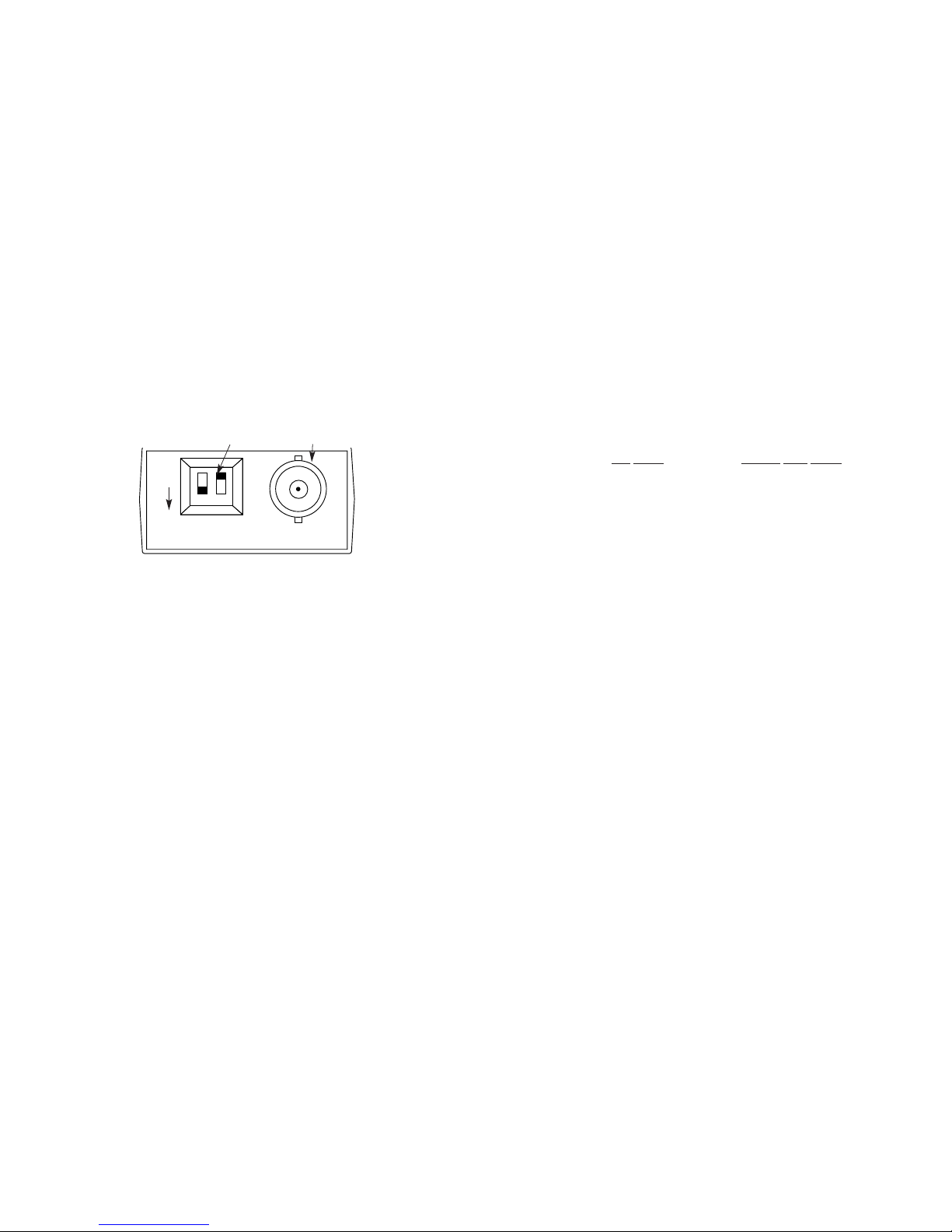
Figure 1 shows the location of the SQE switch, the COL switch and
the BNC coaxial jack.
3.1 CONNECTION TO THE AUI PORT
To establish connection to the AUI port, you must follow these
installation steps:
1. Turn OFF the computer or device to which the Model 2102 is to be
connected.
2. If the Model 2102 will be connected to the AUI port of an Ethernet
interface card, turn the SQE switch ON (the down position). If the
Model 2102 will be connected to the AUI port of an Ethernet hub or
repeater, turn the SQE switch OFF (the up position).
Note: The default is ON.
3. If the Model 2102 will be used with a workstation or terminal server,
turn the COL switch OFF (the up position). When OFF, the MAU
detects collisions only when it is transmitting data. If the Model
2102 will be attached to a repeater (such as a hub), turn the COL
switch ON (the down position). When ON, the COL switch detect
collisions occurring during the transmitting or receiving modes.
Note: The default is OFF.
3
Figure 1. Location of the SQE switch, COL switch and BNC coaxial jack
SQE COL
ON
Switches BNC Coaxial Jack
4. Open the slide latch of the AUI port and insert the Model 2102 into
the DB-15. Lock the slide latch to secure the Model 2102 in place.
If the AUI port is mounted to a card, make sure the card is
configured correctly and the AUI port is enabled.
Note: If connection to the AUI port is through a DB-15 cable, make
sure the cable is wired STRAIGHT THROUGH, with at least the
following signals being passed:
AUI PORT MODEL 2102 DB-15
Signal Pin # Pin # Signal
Data Out+ 3--------------3 Data Out+
Data Out - 10--------------10 Data Out-
Data In+ 5--------------5 Data In+
Data In- 12--------------12 Data In-
Collision In+ 2--------------2 Collision In+
Collision In- 9--------------9 Collision In-
Voltage Common 6--------------6 Voltage Common
Voltage Plus 13--------------13 Voltage Plus
Protective DB-15--------------DB-15 Protective
Ground Shell Shell Ground
3.2 CONNECTION TO THE 10BASE2 NETWORK
To establish connection to the 10Base2 network, you must attach a
BNC T-connector to the BNC coaxial jack (see Figure 1). Then attach
the two portions of BNC cable to the T-connector. If this is one of the
stations at either end of the BNC cable, attach the cable to the BNC
T-connector and attach a 50 ohm BNC termination (load) to the
remaining connection on the BNC T.
See Appendix B for the maximum number of MAUs per segment
and their proper spacing on the coaxial cable.
4

AAPPPPEENNDDIIXX
BB
SPECIFICATIONS
Standard: IEEE 802.3 compliant
Connectors: DB-15 male on AUI port, BNC connector for
connection to 10Base2 coax medium
Collision Parameters: Turn on delay: approx. 7 bits; turn off delay:
max of 20 bits; pulse width: 35-70nS
Jabber Timer Parameters: When the transmitter operates
continuously for approx. 40 mS, the
jabber time turns the transmitter off to
prevent lock-up of the network due to
the jabbering of one station; after a
500mS pause, the transmitter is put
into service again, although it only
transmits when required
Jabber timeout: 20 - 150mS
Jabber reset timeout: 250 - 750mS
Characteristic Impedance: 50+/- 2 ohms (average)
Maximum Segment Thin Coax Length: 185m (600 feet)
Minimum Length Coax Cable Section: 0.5m
Minimum Spacing Between MAUs: 0.5m
Maximum Number of MAUs on a Cable Segment: 30
Power Supply: Supplied via the DB-15 connector on the
AUI connection: pin 13 - Voltage Plus, pin 6
- Voltage Common
Temperature Range: 0-60°C (32-140°F)
Altitude: 0-15,000 feet (0 - 4,500 meters)
Humidity: 5 to 95% noncondensing
Dimensions: 2.25”L x 1.69”H x 0.75”W
Weight: 1.3 oz
6
AAPPPPEENNDDIIXX
AA
SQE
FEATURE
The SQE feature verifies that the Model 2102 transmits packets
correctly: After the node sends each packet, the Model 2102 sends a
pulse back to the node verifying that the Model 2102 has transmitted
the packet correctly. If the Model 2102 is connected to an interface
card, the SQE feature should be ON (the down position). If the Model
2102 is connected to a hub or repeater, the SQE switch should be OFF
(the up position).
5
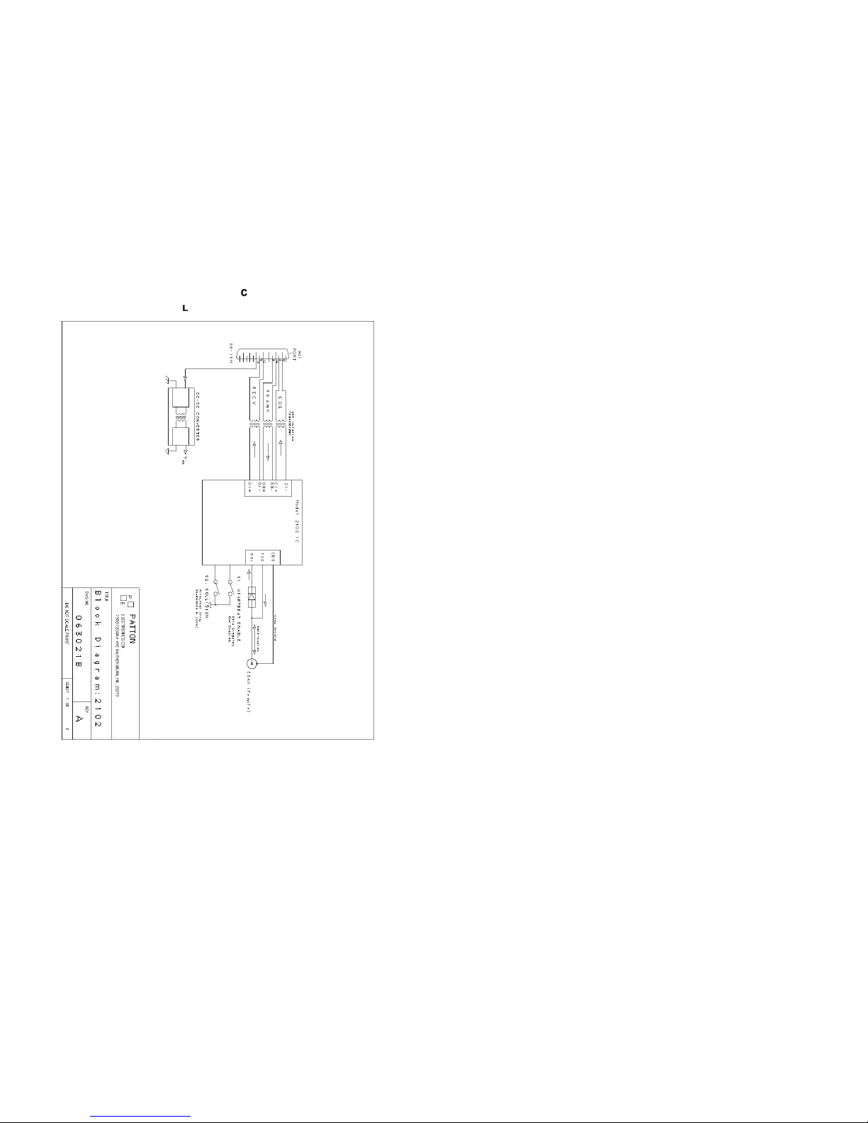
AAPPPPEENNDDIIXX
CC
BLOCK DIAGRAM
7
Table of contents
Other Patton electronics Transceiver manuals


