manuals.online logo
Brands
  1. Home
  2. •
  3. Brands
  4. •
  5. Patty-O-Matic
  6. •
  7. Commercial Food Equipment
  8. •
  9. Patty-O-Matic 330A User manual

Patty-O-Matic 330A User manual

Patty-O-Matic, Inc. ®
The World’s Finest Food Machines
Model 330A
Owner’s Manual
Revised January 2011
Patty-O-Matic Inc.
Route 547 P.O. Box 404 Farmingdale NJ,07727
Tel: (732) 938-2757 Fax: (732) 938-5809
Toll Free in USA: 877-938-5244
Website: www.pattyomatic.com
Email: [email protected]
2
Model 330A Owner’s Manual
Table of Contents
•Introduction to your new machine Page 3
•Installing Mold Plate Guard Page 3
•Installing Feed Tray Page 3
•Accessories Equipped with the Model 330A Page 4
•Parts to Become Familiar with Page 5
•Label Location and Description Pages 6&7
•Operating Procedure Page 8
•Setting Ring Pin Pressure Plate Page 8
•Changing Mold Plate and Spacer Plate Page 9
•Proper Disassembly for Cleaning and Sanitizing Page 10&11
•Installing Patty Paper Page 12
•Points of Lubrication Page 12
Parts Representation
•Feed Tray Assembly Page 13
•Mold Plate Guard Assembly Page 13
•Knock Out Cup Assembly Page 13
•Hopper Assembly Page 14
•Feeder Assembly Page 14
•Assembled Machine Views Page 15
•Paper Interleaver Assembly Page 16
•Ring Pin Pressure Plate Page 17
•Mold Plate Assembly Page 17
•Assembled Hopper and Feeder Page 17
•Electrical Switches Page 18
•TowerAssembly Page19
•Main Shaft Assembly Page 20
•Crank Housing Assembly Page 21
•Motor To Main Shaft Page 22
•Knock Out Cam Assembly Page 23
•Knock Out Shaft and Lever Assembly Page 23
•Main Motor Side View Page 24
•Mold Plate Guide Rails Page 24
•Main Shaft Outside Machine View Page 24
•Wiring Diagram Page 25
•Warranty Information Page 26
•Important Information Guide Page 27
•Notes Page28
3
Thank you and congratulations on the purchase of your new Model 330A
Patty Molding Machine from Patty-O-Matic, Inc! The Model 330A will form,
interleave paper between, and stack patties. This machine is designed for easy
operation and cleaning. Please become familiar with this manual and your
machine will give you many years of productive service.
The Model 330A is shipped to you in at least two cartons which contain the
patty machine, feed tray, mold plate guard, spare parts box, receiving table, and
this manual. If you purchased your machine with any other accessories, such as a
mobile table or patty paper, these items may be in a separate carton. The parts box
that comes with the machine should include a bottle of machine lubricant, a speed
driver, samples of patty paper, and a spare parts kit.
Your machine is equipped with two interlocks. One is located on the front
of the machine and one is located on the top of the machine. The Mold Plate
Guard must be installed on the machine to engage the interlock on the front of the
machine and the Feed Tray including the Guard must be installed on top of the
Hopper to engage the interlock on top of the machine.
Mold Plate
Guard
Mold Plate
Guard Knobs
Plunger and Key
Latch Interlock
Installing the Mold Plate Guard
Loosen Guard Knobs on the Hopper and
place Mold Plate Guard under the fender
washers located under the knobs.
Tighten down on Guard Knobs. To
Activate the interlock switch, slide push
rod against the plunger, inside the
keylatch, and turn rod to the right. This
will lock the push rod in place and
activate your interlock switch.
Installing the Feed Tray
Place stainless steel tube of feed tray over
the Hopper. Make Sure the Switch Plunger
on the bottom of Feed Tray depresses the
Tower Stem inside the Tower Sleeve on
the to
p
of the machine.
Tower Interlock
Hopper
Push Rod
and Collar
Feed Tray
Stainless
Steel Tube
DO NOT ATTEMPT TO RUN THIS
MACHINE WITHOUT THE FEED
TRAY AND THE MOLD PLATE
GUARD IN THEIR PLACE!!
FAILURE TO DO SO COULD
RESULT IN SERIOUS BODILY
INJURIES!!
Switch Plunger Located
on back of Tray
4
Accessories Equipped with the Model 330A
1 2
3
Item# Description Part#
1 SparePartsBox 655
Holds Spare Parts, Patty Paper Sample, Machine Lubricant, Speed Driver, and
Locator Rings
2 Receiving Table 609-6
3 SpeedDriver 544
4 Bottle of Machine Lubricant and Cleaner 600
5 Gallon of Machine Lubricant(Separate Order Only) 600A
6 Machine Locator Rings 610-2
4
6
5
Please become familiar with some of the parts
of your machine prior to operating machine
Feeder
Washer
Feeder
Hopper
Mixer
Collar
Feeder Top
View
Feeder Side
View
Spacer PlateMold Plate Assembly Side View
T-Knob
Mold Plate Assembly Underside View
Back Drive
T-Knob
Hole
Feed Tray Guard
Feed Tray Guard and Mold Plate Guard are installed for
your safety. Do not tamper with them in any way!
Mold Plate Guard
Ring Pin Pressure Plate
Knock Out Cup
Assembly
Refer to Page 12
Meat Stop
Pressure
Plate
Chamber
Lid
X Bolt
6
Proper Label Location for a Model 330A
1
2
3
4
5
6
7
8
9
10
10
11
2
6 12
7
Item # Description Part#
1. Danger Label 3 514-09a
2. Warning Orange 514-02
3. Patty-O-Matic 514-08
4. Safety instructions 514-06
5. Danger Label 1 514-03
6. Danger Label 2 514-00
7. Serial Tag 514-15
8. Store Tool 514-14
9. Warning Manual 514-01
10. Danger on/off 514-05
11. Do Not Pressure Wash 514-04
12. Unplug Machine 514-07
8
Proper Procedure for Operating a Model 330A
When the Model 330A is fully assembled with all guards secured in their proper
place, put product to be portion molded in the Feed Tray. Push the product through the
holes in the Feed Tray Guard into the Hopper opening. DO NOT PUT HANDS OR
FINGERS, OR FOREIGN OBJESTS, SUCH AS STOMPERS OR PLUNGERS
INTO THE HOPPER. THERE ARE NO STOMPERS OR PLUNGERS NEEDED
WHEN USING THIS UNIT, THEREFORE NONE ARE SUPPLIED. After you
allow product to drop into Hopper turn the machine on by moving the On/Off switch
down towards the on position. The machine may need to cycle a few times to prime the
machine with product. As patties are being formed continue to push product through the
holes and under the Feed Tray Guard. Patty paper may be added to the machine as
needed. The machine can hold up to 1 inch of paper at a time, but no more.
As the Mold Plate moves back and forth to form patties, a thin coating of product
may accumulate over its surface. This coating may also accumulate on the edges of the
Knock Out Cup or on the front of the Hopper and Spacer Plate. This accumulation does
occur on all molding machines. It is nothing to be concerned with. There are certain
machine settings that may lessen this accumulation.
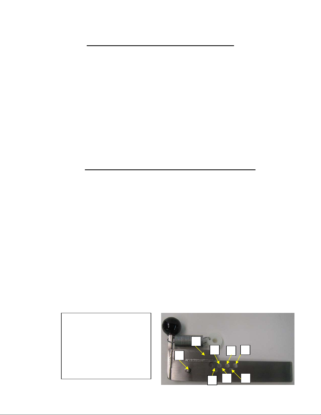
Setting the Ring Pin Pressure Plate for your Patty Size
The Purpose of the Pressure Plate is to entrap the amount of product necessary to form
your patty. This part is also used in controlling the firmness of your patty. With the Pressure
Plate set correctly you will in turn have:
- less leakage, oozing, and coating of parts
- less kneading of your product
- and less strain on your machine.
-----------------------------------------------------------
If your patty weight is 8 ounces, keep the ring pin in the storage hole as described in the
picture. This will allow the Pressure Plate to move all the way into the Hopper and stop on the
welded stop which is the maximum volume setting.
If your patty is 4 ounces remove the ring pin from the storage hole and place it in the 4
ounce hole.
If you patty weight is to be 6 ounces, place the ring pin in the 6 ounce hole.
If you would like to have a tightly packed patty, move the ring pin to a higher than
recommended setting for that particular weight.
THESE ARE ONLY RECOMMENDED SETTINGS. A VARIETY OF CIRCUMSTANCES
MAY CALL FOR YOU TO INSERT THE RING PIN IN A DIFFERENT LOCATION.
12
3
4
5
6
7
8
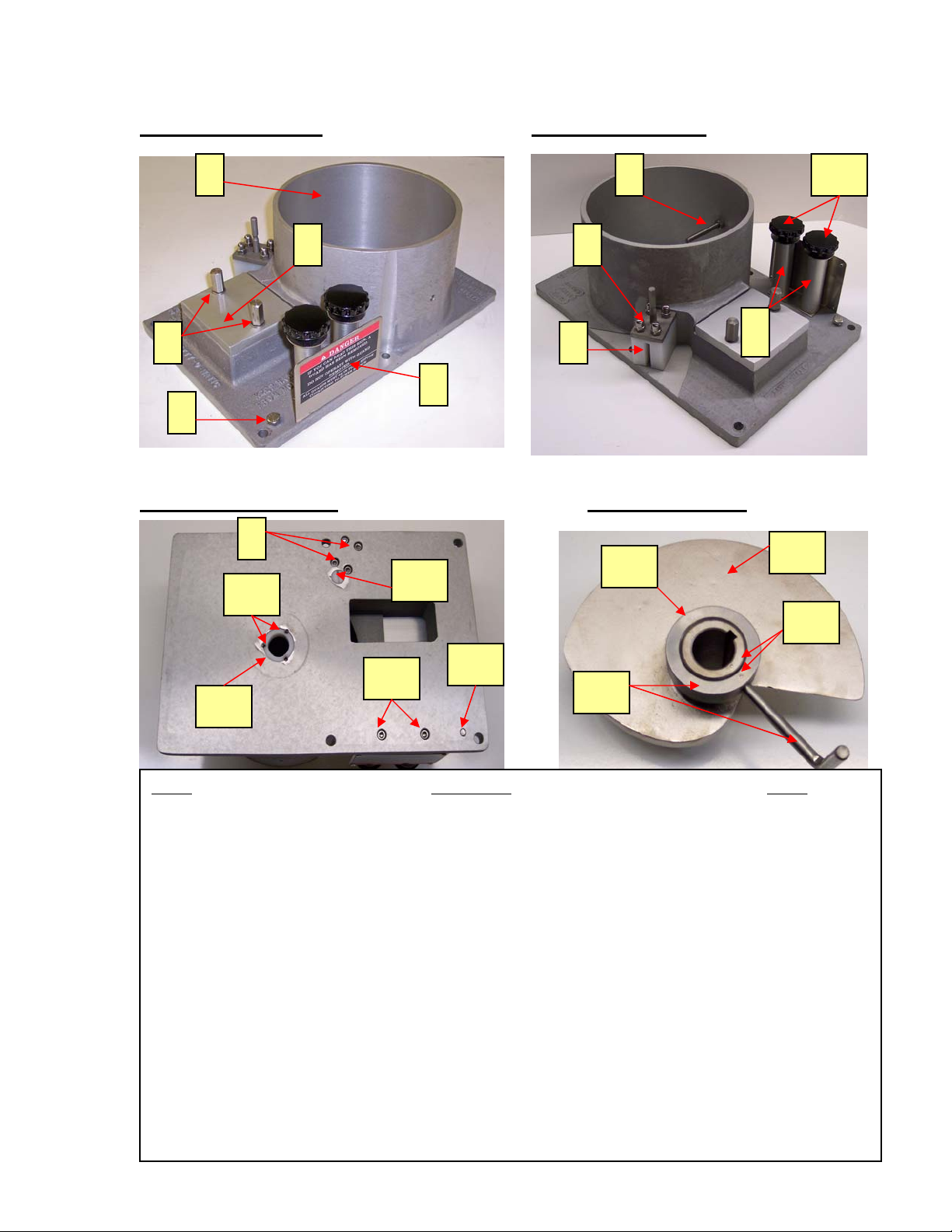
1 - Ring Pin in storage hole
2 - 2 ounce hole
3 - 3 ounce hole
4 - 4 ounce hole
5 - 5ounce hole
6 - 6 ounce hole
7 - 7 ounce hole
8 - 8 ounce welded stop
9
Changing Your Machine’s Mold Plate
Always disconnect the machine from its power source
before attempting to change or clean any of the machines component parts.
First remove the T-Knob from the Back Drive of the Mold Plate, then pull the
Mold Plate out from the back of the machine. If you prefer, remove the Mold Plate from
the machine without removing the T-Knob from the Back Drive. Simply unhook
Connecting Arm from the T-Knob and slide the Mold Plate from the back of the machine.
When changing the Mold Plate always use the corresponding Spacer Plate. The
thickness fraction stamped on the Spacer Plate should match the fraction stamped on the
front right corner of the Mold Plate. For example: if your Mold Plate is stamped “4F ½”
then the Spacer Plate should be stamped “1/2” The Spacer Plate is retained by the X-Bolt.
The X-Bolt is threaded into the Hopper. Turn the X-Bolt counter clockwise enough to
remove the Spacer Plate. There is no need to remove the X-Bolt from the Hopper. After
putting the new Mold Plate and corresponding Spacer Plate into the machine, turn the X-
Bolt into the hole located on the front of the Spacer Plate just enough to hold the plate in
place. DO NOT over tighten X-bolt into hopper. This may cause scoring of the Mold
Plate or other damages to the machine.
Mold Plate and Connecting Arm Rear View
Hopper Front View Spacer Plate Top View
T-Knob
Back Drive
Connecting Arm
Mold Plate
Spacer Plate
X-Bolt
X-Bolt
Location Hole Thickness
Fraction Stamp
Ring Pin
10
Proper Disassembly for Cleaning
Your Model 330A:
Always Unplug Machine From its
Electrical Source Before Cleaning
- Remove Feed Tray by lifting it off the
Hopper, and Mold Plate Guard by
loosening the Mold Plate Guard Knobs,
and unlatching the push rod.
- Remove Pressure Plate by detaching spring
and sliding Pressure Plate from inside of the
Hopper. Remove Feeder by unscrewing the
feeder bolt using speed driver provided.
Remove Feeder Washer by lifting it off the
Feeder and lift Feeder from the inside of the
Hopper.
- Remove Hopper by lifting it off the
Main Shaft of the Machine.
- Remove the four Hopper Bolts using
the speed driver provided. The two bolts
on the Chamber Lid may be removed as
well for additional cleaning.
- After the Hopper is removed from the
machine, remove Spacer Plate from the top of
the Mold Plate. *Note--Occasionally the
Spacer Plate sticks to the bottom of the
Hopper. 3/4” Molds do not use a spacer
plate.
- Remove the Mold Plate by disconnecting
the Connecting Arm from the T-Knob. This
will allow the Mold Plate to be removed from
between the Guide Rails and removed from
the machine. The T-Knob may also be un-
screwed from the Back Drive as an alternate
means of disassembly.
Feed Tray
Mold Plate
Guard
Pressure
Plate
Pressure Plate
Spring
Feeder
Chamber
Lid
Hopper
Bolts
Main Shaft
Hopper
S
p
acer Plate
Mold Plate
Back Drive
T-Knob
Connecting Arm
9
Push Rod
Guard
Knobs
11
- Remove Knock Out Cup By loosening
the Knock Out Knob while holding the
other end of the bolt with the speed driver
provided with the machine.
- All of the parts that were removed from the
machine can now be washed and sanitized
thoroughly. USDA recommends the sanitizing
solution should be 50 parts per million chlorine,
but no more than 200 parts per million. The
machine itself should be cleaned and sanitized
by hand. After all Parts are clean they should
be coated in mineral for added protection.
DO NOT HOSE DOWN OR PRESSURE
WASH THIS MACHINE!
Knock Out Knob
Knock Out Cup
Disassembly
Tool
*To Re-Assemble the Machine reverse the above procedure. Hopper bolts
should only be hand tightened with the speed driver provided.
*The Knock Out Cup Should be installed on the Machine after all other
parts are in place. The Mold Plate should be all the way forward and the
Knock Out Arm should be in the down position for the cup to align with
the Mold Plate
p
ro
p
erl
y
.
Installin
g
Patt
y
Paper on Interleaver:
Place a stack of paper no thicker than one
inch under the Pressure Foot. Slide paper
hole in paper over center pin on. This can
be accomplished without stopping the
machines movement.
*Placing more than one inch of paper
on center pin may cause improper
paper feeding.
Center Pin
Pressure
Foot
Patty-O-Matic Inc. offers the highest quality patty paper, machine lubricant, and
machine grease. Please contact the factory for information on these products.
Toll Free in the U.S.A. 877-938-5244
Outside the U.S.A. 732-938-2757
P.O. Box 404 Farmingdale, NJ 07727
Email: [email protected]
Website: www.pattyomatic.com
Paper Sleeves should be adjusted for different size patty paper
Paper Sleeves
12
Points of Daily Lubrication For
Your Model 330A:
The Following Parts should be lubricated daily to ensure proper machine maintenance
- Pressure Foot should be lifted up
and oiled. Hold the Ball knob and
lift up. Place a few drops of oil
on the Pressure Foot shaft.
Always Unplug Machine and use Food Approved Oil and Grease!
- Knock Out Shaft should be oiled
when the Knock Out Arm is in the
up position. The picture shown
displays the Arm in the up
position.
- Tower Stem should be oiled when
the Feed Tray is removed as shown.
- Rod End Bearings should be oiled
with a few drops of oil. There are
two Rod End Bearings to be oiled. Do
not allow oil to drip onto the
Conveyor Belt.
Main Shaft
- Main Shaft should be oiled when the
machine is disassembled as shown in this
picture. Be sure to oil under the collar by the
machine cabinet.
- The inside of the machine can be oiled
through the Rear Inspection Opening. By
spraying oil here you will be oiling the inside
components.
- The Grease Fitting in the back of the machine
should be greased once every two weeks. 3 to
4 shots of grease are recommended.
Tower Stem
Pressure
Foot shaft
Knock Out Shaft
Ball Knob
Knock Out
Arm
Rod End
Bearings
Conveyor
Belt
Rear Inspection
Opening
Grease Fitting
13
Poly Coved Feed Tray Mold Plate Guard Assembly
Knock Out Cup Assembly Knock Out Cup Exploded View
1
2
3
4
6
5
7
8
9
10
7
9
10
11
12
13 14
Item# Description Part#
1 Feed Tray Guard Assembly 543
2 Feed Tray Guard Hardware 541-B
3 Stainless Steel Flange Support 554
4 Mold Plate Guard Assembly 550SC
5 Push Rod Collar 553-1B
6 Push Rod 553-5
5&6 Push Rod and Collar Assembly 553
7 Knock Out Knob 571-7
8 Knock Out Arm (partial view) 502B
9 Knock Out Cup Plastic Washer 571-6
10 Round Knock Out Cup(Specify Size) 571-1
11 Knock Out Cup Flat Washer and Lock Washer 571-8
12 Knock Out Air Valve (shown in red for visual affect) 571-4
13 Knock Out Cup Bolt 571-9
14 Knock Out Cup Fender Washer 571-10
15 Feed Tray Tower Plunger and Bolt 620-17
*Numbers 5 & 6 also
come as an assembly
*Knock Out Cup Hardware is also sold as an assembly.
-Knock Out Cup Assembly w/ Hardware is Part #571
-Knock Out Cup Hardware Only is Part #571-H1
15
Machine may be equipped with a different tray
14
Hopper Front View HopperRearView
Hopper Bottom View FeederTopView
1
2
3
4
5
8
6
7
9
10
7
11
4
12
13
14
15
17
16
18
Item# Description Part#
1 Hopper Casting 545
2 Chamber Lid 545-A
3 Hex Hold Down Bolt (also used as Hopper hold down) 556B
4 X-Bolt 570
5 Guard Post Guard Information Plate 551-B
6 Meat Stop c/w Washer 555
7 Pressure Plate Block Hardware 548-C
8 Pressure Plate Block 547
9 Mold Plate Guard Post (2) 551
10 Mold Plate Guard Knob and Washer(2 Required) 550-1
11 Hopper Threaded Plug 607
12 Guard Post Screw 551-A
13 Hopper Nylon Bushing 603
14 Hopper Nylon Bushing Set Screw(3 Required) 604
15 Feeder 557
16 MixerCollarSetScrew 559
17 MixerCollar 558
18 Witness Marks (one on Feeder and Mixer Collar for location) N/A
.
.
15
Machine Front View Machine Left Side View
Machine Right Side View Machine Rear View
1 2
3
4
56
78
9
10
11 13
14
15
16
12
17
18
19 20
21
22
23
24
25
26
27
28
29
30
Item # Description Part #
1 Paper Interleaver Arm and Bolts 505
2 Knock Out Arm and Bolts 502B
3 Knock Out Cup 571-1
4 Paper Weight 532
5 Large Knock Out Bumper 504
6 Knock Out Shaft 449
7 Conveyor Belt 534
8 Pressure Bolt Tip 506D
9 Pressure Bolt 506
10 Pressure Foot Spring 508
11 Pressure Foot Ball Knob 506B
12 Paper Interleaver Arm Bolt(2) 505-1
13 Knock Out Shaft Acorn Nut 503
14 Knock Out Spring Tab 498C
15 Knock Out Spring 490
16 Knock Out Arm Bolt(2) 502-1
17 Knock Out Shaft Bushing (white bushing
that is pressed into Machine Frame)
462
18 Paper Interleaver Arm Bushing (white
poly bushing) 505-1B
Item# Description Part#
19 Feed Tray Tower Sleeve 620-16
20 Feed Tray Tower Block 620-6
21 Tool Holder 601
22 On/Off Switch 500
23 Power Cord 115-01
24 On/Off Switch Guard 501
25 Key Latch 609-A1
26 Plunger Switch 608-1B
27 Ring Pin Pressure Plate 546-3
28 Mold Plate Back Drive 564
29 Connecting Arm 455
30 T-Knob 567
31 Grease Fitting PS701
32 Knock Out Spring Cotter Pin 490D
33 Ring Pin 546C
34 Weight Shaft Support Hardware 530
35 Pressure Foot Hardware 507
Many parts are also sold as assemblies. Please
contact the factory for further information:
Toll Free in the U.S.A. 877-938-5244
Outside the U.S.A. 732-938-2757
31
32
33
34
34
16
Paper Interleaver Top View
(Conveyor Belt is Removed for Visual) Paper Motor
Paper Return Bracket
1
2
5
6
7
4
5
4
8
9
10
10
11
12
1
13
14
15
16
17
18 19
20
21
22
23
24
25 26
27
28
29
30
31
Item # Description Part #
1 Paper Interleaver Motor c/w
Extension Shaft 516
2 Weight Shaft 527
3 Weight Shaft Support 529
4 Rod End Hardware 523
5 Rod End Bearing (2 required) 522
6 Paper Interleaver Front Pulley 521
7 Paper Weight (2 required) 532
8 Interleaver Adjustment Slots N/A
9 Paper Interleaver Back Pulley 520
10 Pin Holder Bolt and Nuts
(2 required) 526
11 Paper Pin, Nuts, and Washers 525
12 Paper Pin Assembly 524-A
13 Motor Extension Shaft and Screws 517
14 Paper Sleeve Stop 248A
15 Stainless Steel Paper Pivot Rod(2) 247
3
Item# Description Part#
16 Paper Stop 248
17 2 Return Bracket Mounting Screws249
18 Left Return Spring 246L
19 Right Return Spring 246R
20 Spring Adjusting Collar
(2 required) 244
21 Set Screw (one in each collar) 245
22 Pivot Rod Support Bracket 243
23 Interleaver Motor Cover 537
24 Interleaver Support Hardware 499
25 Paper Attachment Support Bar 497
26 Interleaver Support Bar Spacer 498
27 Weight Shaft Hardware 528
28 Motor Cover bolts (2 Required) 538
29 Conveyor Belt 534
30 Conveyor Belt Guard 536
31 Paper Interleaver Casting Frame 519
32 Weight Shaft Spacers (Not Shown) 531
32
17
Ring Pin Pressure Plate Mold Plate Bottom View
Mold Plate Side View
Hopper and Feeder Assembled Top View
5
3
1 2
4
6
7
89
11
12
10
13
16
15
14
17
Feeder Washer
& Shear Pin
Hold Down
Bolt
16
18
1515
Item # Description Part #
1 Pressure Plate Ball Knob 546D
2 Pressure Plate Spring 549
3 Ring Pin Adjustment Holes N/A
4 Ring Pin(shown in
the storage hole) 546C
5 Ring Pin Pressure Plate 546-3
6 Back Drive Stop Bolt Nut 566
7 Back Drive Stop Bolt 565
8 Mold Plate Back Drive 564
9 Air Grooves (colored for visual) N/A
10 Round Mold Plate 563-1
11 Set of Back Drive Hardware 568A
12 Back Drive Clamp 568
Item # Description Part #
13 T-Knob 567
14 Hopper Casting 545
15 Hold Down Bolt 556B
16 Feeder Washer 560
17 Meat Stop 555
18 Shear Pin 562
19 Spacer Plate( Specify Size) 569
Part # 563 - Mold Plate Assembly
-Includes Round Mold Plate,
Back Drive Assembly and
Knock Out Cup Assembly
Other Shapes Available
19
Spacer
Plate
18
Machine Switches Front View Guard Switch Interior View
On/Off Switch Interior View Tower Switch Interior View
1 2 3
4
5
6
7
8
4
3
9
5
10
11
Item# Description Part#
1 Key Latch 609-A1
2 Plunger Switch Boot 608-1C
3 On/Off Switch Guard 501
4 On/Off Switch Boot 500B
5 Power Cord 115-01
6 Wire Grommet 487
7 Guard Switch 608-1B
8 Guard Switch Wire 608-1D
9 On/Off Switch (shown insulated in electrical tape) 500
10 Tower Switch 620-10B
11 Tower Switch Wire 620-10A
6
Many other parts are also sold as
assemblies. Please contact the factory
for further information:
Toll Free in the U.S.A. 877-938-5244
Outside the U.S.A. 732-938-2757
Part # 608-5A – Includes Guard
Switch and Wire
Part # 620-10 – Includes Tower
Switch and Wire
19
Tower Assembly w/ Tower Block Tower Assembly
Exploded Bottom View
Tower Assembly Tower Assembly
Inverted Top View Machine View
1
3
4 5
6
7
3
10
6
3
2
11
12
9
1
1
2
3
4
8
Item# Description Part#
1 Tower Sleeve 620-16
2 Tower Stem 620-3
3 Tower Tube 620-5
4 Tower Block 620-6
5 Tower Locator Lock Bolt 620-7
6 Tower Switch 620-10B
7 Rubber Seal 464S
8 Tower Block Hardware 620-8
9 Tower Jam Nut 620-06
10 Tower Spring 620-9
11 Tower Acorn Nut 620-15
12 Tower Bushing 620-4
Many parts are also sold as assemblies. Please
contact the factory for further information:
Toll Free in the U.S.A. 877-938-5244
Outside the U.S.A. 732-938-2757
20
Main Shaft Assembly Interior View Main Shaft
Exploded View
1
2
3
4
5
6
7
1
2
7
9
10
3
8
11
12
5
15
10
9
13
Item# Description Part#
1 Main Shaft Bushing (pressed into Machine Frame) 470
2 Main Shaft Thrust Washer 469-1
3 Timing Sprocket 465T
4 Chain Tension Adjuster Bolt 463
5 Main Shaft Bearing (pressed into Machine Frame) 464A
6 Timing Chain and Link 471
7 MainShaftClamp 467
8 Main Shaft Clamp Hardware 468
9 Main Shaft Fender Washer and Hardware 240-1
10 Main Shaft Driven Sprocket(Specify Amount of Teeth) 240
11 Main Shaft Threaded Insert Set Screw 464-2
12 Main Shaft Threaded Insert 464-1
13 Main Shaft Sprocket Key 241
14 330A Grease Line System(Not completely shown) 704
15 Main Shaft C/W Insert and Set Screw 464
14

Other manuals for 330A

1

Other Patty-O-Matic Commercial Food Equipment manuals

Patty-O-Matic Protege User manual

Patty-O-Matic

Patty-O-Matic Protege User manual

Patty-O-Matic 330A User manual

Patty-O-Matic

Patty-O-Matic 330A User manual

Patty-O-Matic PR12 User manual

Patty-O-Matic

Patty-O-Matic PR12 User manual

Patty-O-Matic Protege User manual

Patty-O-Matic

Patty-O-Matic Protege User manual

Patty-O-Matic PS21 User manual

Patty-O-Matic

Patty-O-Matic PS21 User manual

Patty-O-Matic 330PUB User manual

Patty-O-Matic

Patty-O-Matic 330PUB User manual

Patty-O-Matic Pacesetter User manual

Patty-O-Matic

Patty-O-Matic Pacesetter User manual

Popular Commercial Food Equipment manuals by other brands

freor JUPITER Operation manual

freor

freor JUPITER Operation manual

ELRO PRECIPAN installation manual

ELRO

ELRO PRECIPAN installation manual

frost-trol GREGAL Installation and maintenance manual

frost-trol

frost-trol GREGAL Installation and maintenance manual

La Marzocco Strada AV manual

La Marzocco

La Marzocco Strada AV manual

Lincoln V2500 Series Service manual

Lincoln

Lincoln V2500 Series Service manual

Electrolux SkyLine ChillS 202 user manual

Electrolux

Electrolux SkyLine ChillS 202 user manual

Baba Gas Fired Tandoor instruction manual

Baba

Baba Gas Fired Tandoor instruction manual

etol blubox 13 user manual

etol

etol blubox 13 user manual

Delfield Mark7 installation manual

Delfield

Delfield Mark7 installation manual

Angelo Po 1N1BR2E user manual

Angelo Po

Angelo Po 1N1BR2E user manual

Costan OPERA SV GREEN User instructions

Costan

Costan OPERA SV GREEN User instructions

Diamond FABY 1 manual

Diamond

Diamond FABY 1 manual

Amitek AK903P33X Installation - use - maintenance

Amitek

Amitek AK903P33X Installation - use - maintenance

Tefcold MD702 user manual

Tefcold

Tefcold MD702 user manual

Tower Hobbies Presto PT16021GRY Safety and instruction manual

Tower Hobbies

Tower Hobbies Presto PT16021GRY Safety and instruction manual

Vivo CANDY-V002 instruction manual

Vivo

Vivo CANDY-V002 instruction manual

Henny Penny LOV Gas 200 Series quick start guide

Henny Penny

Henny Penny LOV Gas 200 Series quick start guide

Hendi 262214 user manual

Hendi

Hendi 262214 user manual

manuals.online logo
manuals.online logoBrands
  • About & Mission
  • Contact us
  • Privacy Policy
  • Terms and Conditions

Copyright 2025 Manuals.Online. All Rights Reserved.