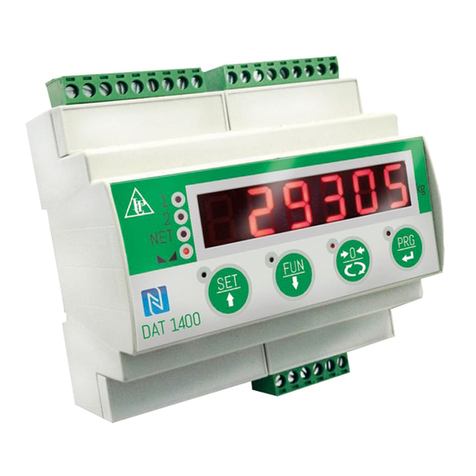
Pavone Systems DAT11 User manual

PAVONESYSTEMS
TECHNICAL MANUAL
DAT11 Serial and analog weighing Indicator/Trasnmitter
Software version P33301

Page II

Rel ID 21100301 Sw. 0.3
Page 1
TABLE OF CONTENTS
WARNINGS.................................................................................................. Page 2
INTRODUCTION ........................................................................................... Page 3
TECHNICAL FEATURES................................................................................... Page 4
INSTALLATION .............................................................................................. Page 5
FRONT PANEL............................................................................................... Page 13
USING THE KEYBOARD ................................................................................. Page 14
DISPLAY INDICATIONS................................................................................... Page 17
OPERATING FUNCTIONS .............................................................................. Page 18
SET-UP .......................................................................................................... Page 22
DIAGRAM OF THE MENU .............................................................................. Page 26
CONFIGURATION PARAMETERS..................................................................... Page 27
CALIBRATION................................................................................................ Page 27
ANALOG PARAMETERS ................................................................................. Page 32
SERIAL PARAMETERS...................................................................................... Page 34
INPUT/OUTPUT PARAMETERS......................................................................... Page 44
WEIGHING PARAMETERS .............................................................................. Page 47
FILTER - SETTING FILTER PARAMETERS .............................................................. Page 49
SETTING FUNCTIONAL FEATURES .................................................................. Page 51
UPLOAD/DOWNLOAD FUNCTION ................................................................ Page 54
ACCESS VIEWING ........................................................................................ Page 54
ALIBI MEMORY.............................................................................................. Page 55
SERIAL COMMUNICATION PROTOCOLS ........................................................ Page 56
FIELDBUS PROTOCOL .................................................................................... Page 67
TROUBLESHOOTING ..................................................................................... Page 79

Page 2
WARNINGS
READ this manual BEFORE operating or servicing on the instrument.
FOLLOW these instructions carefully.
SAVE this manual for future use.
CAUTION
The installation and maintenance of this instrument must be allowed
to qualified personnel only.
Be careful when you perform inspections, testing and adjustment
with the instrument swithced on.
Failure to observe these precautions may be dangerous.
All connections must be performed when the instrument is switched
off.
DO NOT allow untrained personnel to work, clean, inspect, repair
or tamper with this instrument.

PAVONE SISTEMI
Page 3
INTRODUCTION
The DAT11 is a weight transmitter to be matched to the load cells to detect the weight in every situation.
The module is easy to install and can be mounted on 35 mm DIN rail.
The display allows easy reading of the weight, the configuration parameters and errors.
The 3 keys located below the display and protected by the front door allow the Operator to perform
the functions of ZERO and CALIBRATION as well as datasheet and real calibration.
The DAT11 with its multiple serial interfaces (RS485, RS232, ASCII and Modbus RTU protocols) can
be connected to PC, PLC and remote units.
The analog output (0÷20 mA, 4÷20 mA, 0÷10 Vdc, 0÷5 Vdc) allows an additional interfacing to PLC
and remote displays.
The DAT11 also has two programmable SET POINTs to utilize as levels, set points, etc.
AVAILABLE VERSION:
• DAT 11/A: version with the analog output.
• DAT 11/PROFINET: weight transmitter with RS232 serial output, USB and PROFINET.
• DAT 11/ETHERNET IP: weight transmitter with serial output RS232 and ETHERNET IP.
• DAT 11/ETHERCAT: weight transmitter with serial output RS232 and ETHERCAT.
• DAT 11/ETHERNET: weight transmitter with serial output RS232 and ETHERNET.
• DAT 11/PROFIBUS: weight transmitter with serial output RS232 and PROFIBUS.
• DAT 11/CANOPEN: weight transmitter with serial output RS232 and CANOPEN.
IDENTIFICATION PLATE OF THE INSTRUMENT
It’s important to communicate this data, in the event of a request for information. The software number
and release number are shown on the cover of the manual and also displayed when the instrument is
switched on.
WARNINGS
The following procedures must be performed by qualified personnel.
All connections must be performed when the instrument is switched off.

Page 4
TECHNICAL FEATURES
Power supply 24 Vdc ±10% protected against reverse polarity.
Protection with resettable fuse.
Max. absorption 3W
Isolation Class II
Operating temperature -10°C ÷ +50°C (max. humidity 85% non-condensing)
Storage temperature -20°C ÷ +60°C
Weight display Numerical 6 red led digits and 7 segments (h 7 mm)
Led 2 LEDs of 3 mm
Keyboards 3 mechanical keys (behind the red front door)
Overall dimensions 112 x 119 x 23 mm (l x h x w) including term. boards.
Installation Brackets for DIN section or OMEGA bar
Material Self-extinguishing Blend PC/ABS
Connections Removable screws terminal boards, pitch 5.08 mm
Load cells Input max. 4 of 350 Ω in parallel (or 8 cells of 700 Ω).
Load cell excitation 4 Vdc
Linearity <0.01% of the full scale
Temperature drift <0.001% of the full scale / °C
Internal resolution 24 bit
Measuring range -7,6 ÷ +7,6 mV/V
Digital filter To be selected from 0.1 Hz to 250 Hz
Number of decimals weight 0 ÷ 4 decimal places
Calibration of zero and full scale From the buttons.
Check of load cell cable interruption Always present
Logic outputs (DAT11/A) 2 relay outputs with No contact(0,1A, 24 Vdc/Vca)
Logic Inputs (DAT11/A) No. 2 opto-isolated
Serial ports RS232 half duplex
RS485 half duplex
USB C Device
Baud rate 2400 ÷ 115200 baud
Maximum cable length 15m (RS232) and 1000m (RS485)
Optional Fieldbus PROFIBUS DP V1, PROFINET, CANOPEN, ETHERNET
IP, ETHERCAT, ETHERNET
Ethernet Protocols TCP, Modbus/TCP, UDP, IP, ICMP, ARP. Web server
integrated
Communication mode TCP server
Buffer size 256 byte
Connection Timeout Min 30 seconds - Max 90 seconds
Link Timeout (no cable connection) 30 seconds
Analog output (DAT 11/A) Voltage: ± 10 V / ± 5 V (min. 10 KΩ)
Current: 0÷20 mA / 4÷20 mA (max 300 Ω)
Resolution 16 bits
Calibration Digital from keys
Linearity 0.03% of the full scale
Temperature drift 0.002% of the full scale / °C
Microcontrollor ARM Cortex M0+ to 32 bit, 256KB Flash
reprogrammable on-board by USB..
Memoria dati 32 Kbytes expandable up to 1024 Kbytes
In compliance with the standards EN61000-6-2, EN61000-6-3 EN61326-1:2013 for EMC
EN61010-1 for Electrical Safety

23
2423222120191817
-
+
0 V
+24 Vdc
GND
+ Vdc
Page 5
INSTALLATION
GENERAL INFORMATION
The DAT11 consists of a motherboard, to which are added the options available, accommodated in a
plastic enclosure for DIN rail 35mm.
The DAT11 should not be immersed in water, subjected to jets of water and cleaned or wa-
shed with solvents.
Do not expose to heat or direct sunlight.
OVERALL DIMENSIONS
ELECTRIC INSTALLATION
DAT11 is equipped with removable screw, pitch 5.08 mm.
The load cell cable must be shielded and channeled away from power cables to prevent
electromagnetic interferences.
INSTRUMENT POWER SUPPLY
The instrument is powered through the terminals 23 and 24. The
power supply cable must be channeled separately from other cables.
The internal circuit is galvanically isolated from the supply voltage.
Power supply voltage: 24 Vdc± 10%, max. 3W

1234567
8910111213141516
EXC-
EXC+
SENSE+
SENSE-
SIG-
SIG+
SHIELD
2+SGN
3-EXC
6+EXC
1-SGN
5+SNS
4-SNS
7SHD
+EXC
-EXC
+SGN
-SGN
SHD
1
2
3
4
5
+EXC
-EXC
+SGN
-SGN
SHD
1
2
3
4
5
+EXC
-EXC
+SGN
-SGN
SHD
1
2
3
4
5
+EXC
-EXC
+SGN
-SGN
SHD
1
2
3
4
5
J-BOX CGS4/C
+EXC
-EXC
+SGN
-SGN
SHD
+EXC
-EXC
+SGN
-SGN
SHD
+EXC
-EXC
+SGN
-SGN
SHD
+EXC
-EXC
+SGN
-SGN
SHD
24 VDC 3W
DAT 11
SENSE+
SENSE- RX/TX+
RX/TX-
SHIELD
A. GND
I OUT+
V OUT+
S.GND
SIGN+
SIGN-
EXC+
EXC-
+VDC
OUT1
OUT2
IN2
COM
RXD
TXD
GND
SHD
COM
IN1
19
20
21
22
17
18
3
23
24
5
6
7
9
8
414
11
16
13
12
15
2
1
10
+24V
25 PIN CONNECTOR
Page 6
LOAD CELL CONNECTIONS
The cable of the load cell (or load cells) should not be channeled
with other cables, but has to follow its own path.
The instrument can be connected up to maximum 4 load cells of 350
ohm in parallel. The supply voltage of the load cells is 4 Vdc and is
protected by temporary short circuit.
The measuring range of the instrument involves the use of load cells
with a sensitivity of up to 7,6 mV/V.
The cable of the load cells must be connected to terminals 10-16 of
the 7-pin removable terminal board. In the case of 4-wire load cell
cable, jump terminals 11 with 14 and 12 with 13 .
Connect the cell cable shield to the terminal 10.
In the case of the usage of two or more load cells, use special jun-
ction boxes (CEM4/C or CSG4/C).

123456789
10111213141516
2423222120191817
SHD
Rx/Tx+
Rx/Tx-
RS485
Max 32 unit
(1000m max)
123456789
10111213141516
2423222120191817
TXD
RXD
S.GND
SHD
RS232
(20m max)
2423222120191817
INPUTS
24 VDC
INPUT 2
INPUT 1
+
-
COM. INPUT
In 2
In 1
Com
2423222120191817
OUTPUTS
24 Vdc/ac
100 mA Max
OUTPUT 1
OUTPUT 2
COM. OUTPUT
Out 2
Out 1
Com
Page 7
RELAY OUTPUTS
The two outputs are with contact normally open.
Each contact is 24 Vdc/Vac, Max. 100 mA.
The connections cable should not be channeled with power cables.
The connection should be as short as possible.
SERIAL COMMUNICATION
RS232:
The RS232 serial port is always present and can handle several
protocols.
To achieve the serial connection use a suitable shielded cable and
make sure to ground the screen at one of the two ends: to pin 6, if
attached on the side of the instrument, to the ground, if connected
on the other side.
The cable must not be channeled with power cables, maximum
length of 15 meters (EIA RS-232-C), beyond which you should take
the optional RS485 interface.
RS485:
The RS485 serial port (2-wire) is only present in the model DAT11/
RS485.
To achieve the serial connection use a suitable shielded cable and
make sure to connect the shield to one of two ends: to pin 6, if
connected on the side of the instrument, to the ground if connected
on the other side.
The cable must not be channeled with power cables.
LOGIC INPUTS
The two logic inputs are opto-isolated.
The connection cable should not be channeled with power cables .
The function of the two inputs is as follows:
INPUT 1* TARE/ZERO
INPUT 2 PRINT
The activation of the two functions is accomplished by bringing the
external 24 VDC power supply to the corresponding terminals as
shown in the figure here beside.
* Activating the INPUT 1 when the gross weight is positive, it switches
the display from gross weight to net weight. When the gross weight
is negative, gross weight is zeroed.

12345678910111213
141516
2423222120191817
V OUT+
I OUT +
A GND
Analog
Output
Page 8
DAT11/A TRANSMITTER
ANALOG OUTPUT
The instrument provides an analog output in current and voltage.
Analog voltage output: range from -10 to +10 V or -5 to +5 volts,
10K ohm minimum load.
Analog current output: range from 0 to 20 mA or 4 to 20 mA. The
maximum load is 300Ω.
To achieve the connection, use a shielded cable, making sure to
connect the shield to one of the two ends.
USB DEVICE ( SPECIFICATION 2.0 COMPLIANT; FULL-SPEED 12 MBPS)
Use this communication port to directly interface a PC via a USB port.
Use a standard USB cable for the connection.
To connect the instrument via the USB device, you must install a driver
on the PC which is suitable for the operating system used.
For installation please follow the specific instructions.
FIELDBUS CONNECTIONS
As an alternative to the RS485 serial port some of the most common
fieldbuses are available. You can use a single fieldbus which must
be specified when ordering.
ETHERNET CONNECTION
On the lower left part of the instrument there is a RJ45 connector
for Ethernet.
Features:
Trasmission speed 10 Mbps
Network compatible with 10/100/1000 Base-T
TCP Ethernet protocols, Modbus/TCP, UDP, IP, ICMP, ARP
TCP server communication mode
LED indicators (2) Presence of Ethernet and communication/diag-
nostics line
Buffer size 256 bytes
Connection Time-out Min 30 seconds - Max 90 seconds
Link Time-out (cable disconnected) 30 seconds

1 2 3 4 5 6 7 8
1 2 3 4 5 6 7 8
TX+
RX+
RX-
TX-
TX+
RX+
RX-
TX-
1TX+
2TX-
3RX+
6RX-
1 RX+
2 RX-
3 TX+
6 TX-
DIRECT ETHERNET CABLE
1 2 3 4 5 6 7 8
1 2 3 4 5 6 7 8
TX+
RX+
RX-
TX-
RX+
TX+
TX-
RX-
1TX+
2TX-
3RX+
6RX-
1 TX+
2 TX-
3 RX+
6 RX-
CROSSOVER ETHERNET CABLE
Page 9
PIN DESCRIPTION
1 TX+
2 TX-
3 RX+
4
5
6 RX-
7
8
To connect to the MASTER, use a standard twisted pair Ethernet
cable with RJ45 connector.
The RJ45 Ethernet connection cable has a variable maximum length,
depending on the type of cable. A common Cat5 shielded cable
can have a maximum length of about 180 m.
• You can connect the Ethernet communication port directly to the
PC, without having to go through other network devices (routers,
switches, hubs, LAN-bridge or the like), but special RJ45 cables must
be used, called “crossover.”
• Normally cables are the “direct” type and allow connection to
network devices such as routers or hubs, but not direct connection to
two PCs (even if there are currently network cards with auto-sensing
technology, which recognize the type of
cable and the type of connection, allowing
direct PC-PC connections as well as using
non cross-over cables).
• On side are diagrams of the two types
of cables mentioned and their connection
diagram.
ETHERNET / IP CONNECTION
Ethernet / IP is a real-time industrial protocol which is based on the
Ethernet network.
There are two RJ45 connectors to allow connection of multiple instru-
ments in the same network.
Refer to the previous page for connection notes and warnings.
Features:
10 and 100 Mbit operation, Full and Half Duplex
Up to 128 bytes of I / O fieldbus in every direction.

Page 10
PROFINET CONNECTION
The Profinet connector is RJ45, the same as the Ethernet interface.
There are two RJ45 connectors to allow connection of multiple instru-
ments in the same network.
Refer to the previous page for connection notes and warnings.
Features:
PROFINET IO Real Time (RT) communications
Up to 128 bytes of I/O fieldbus in every direction.
ETHERCAT CONNECTION
EtherCAT is a real-time industrial protocol which is based on the
Ethernet network.
EhterCAT The protocol requires that the RJ45 connectors have the
function of IN and OUT.
Putting more DAT11 instruments in series, the MASTER will be con-
nected to the IN connector of the first DAT11, whose OUT connector
will be connected to the IN connector of the next etc ...
Refer to the previous page for connection notes and warnings.
MAC ADDRESS IN INSTRUMENTS WITH INDUSTRIAL FIELDBUS
ETHERNET.
Instruments which install Hilscher modules with Industrial Ethernet
Protocol (Profinet, EthernetIP, EtherCAT, etc.) have a label under the
connectors, as shown.
This label shows the MAC address of the module (red box), the
identification number of the module (blue box) and a QR code that
contains the MAC address. The latter can be read using a smart-
phone app for reading QR codes (eg. on Google Play store, “QR
Code Reader”).

3 B_LINE
4 RTS
5 GND BUS
6 +5V BUS
8 A_LINE
1 5
6 9
Page 11
PROFIBUS DP CONNECTION
Pin Signal Description
1 - -
2 - -
3 B line +RxD/+TxD, level RS485
4RTS Request to send
5 GND Ground (isolated)
6 + 5V Bus Output +5V termination (isolated)
7 - -
8 A line -RxD/-TxD, level RS485
9 - -
Housing Cable shield Internally connected to protective
earth according to Profibus
specification
For connection to the Profibus Master, use a standard Profibus cable.
The typical impedance of the cable should be between 100 and
130 Ohms (f> 100 kHz). The cable capacity (measured between
conductor and conductor) should be less than 60 pF / m and the
minimum cable cross section should not be less than 0.22 mm2
In a Profibus-DP network, you can use either cable type A to type B
cable, depending on the required performance. The following table
summarizes the features of the cable to be used:
Specification Type A Cable Type B Cable
Impedance from 135 to 165 ohm
(f = 3 – 20 MHz)
from 100 to 300 ohm
(f > 100 kHz)
Capacity < 30 pF/m < 60 pF/m
Resistance < 110 ohm/km -
Conductor cross
section
> 0,34 mm2> 0,22 mm2
The following table shows the maximum length of the wires line with
cable type A and type B, function of the different communication
speed required:
Baud rate
(kbit/s) 9.6 19.2 187.5 500 1500 3000 6000 12000
Cable A
lenght (m) 1200 1200 1000 400 200 100 100 100
Cable B lenght
(m) 1200 1200 600 200 - - - -
For a reliable operation of the Fieldbus, should be used a line ter-
mination at both ends.
In the case of multiple DAT 11 instruments, use the line termination
at only one instrument.
For configuring the instrument, the GSD file is available (hms_1810.
gsd) that must be installed in the master.

2
3
1 5
6 9
7
CAN_L
CAN_H
Page 12
CANOPEN CONNECTION
Pin Signal Description
2 CAN_L CAN low bus line
3 CAN_GND
7 CAN_H CAN high bus line
CANopen is an higher-layer communication protocols based on a
CAN seria bus system.
For the connection using a cable with a twisted pair differential and
common return in accordance with ISO 11898. The length of the
bus is limited by the speed of communication chosen according to
the following table:
Bit Rate Max. Bus lenght
1 Mbit/sec 25 m
500 Kbit/sec 100 m
250 Kbit/sec 250 m
125 Kbit/sec 500 m
<=50 Kbit/sec 1000 m
The CAN line must have the resistance of 120Ω termination.
The reference CAN_GND must be connected to earth at one point
of the line.
The cable can not be channeled with power cables.
For the configuration of the card is available ESD file that must be
installed in the master.

Page 13
FRONT PANEL
The DAT11 transmitter has a front door that protects the 6 digits display, the 2 status LEDs and the
three front keys.
In operating mode the display shows the weight and the LEDs indicate the status of weight (net-gross).
The set-up parameters are easily accessible and can be changed through the use of the three front keys
used to select, edit, confirm and save the new settings.
DISPLAY
The 6-digit display normally shows the weight on the scale. According to the various programming
procedures, the display is used for programming the parameters to be stored in the memory, i.e. the
messages that indicate the type of operation in progress and, therefore, help the Operator to manage
and program the instrument.
STAND-BY FUNCTION
The display can take on the stand-by mode, during which time the display brightness is reduced and
the keypad is locked. All other functions of the instrument are up and running.
See the paragraph on the activation / deactivation of the stand-by mode.
LED INDICATORS
To the right of the display there are 3 LED indicators:
LED 1 (on = stable weight)
LED 2 (on = net weight indication)
LED 3 (zero band = gross weight within the Zero Band value).
LED 1 Stable weight
LED 2 Net Weight
LED 3 Zero band

Page 14
USING THE KEYBOARD
The instrument is programmed and controlled through the 3 keys keyboard, with the following functions
SYMBOL DESCRIPTION
J
Short press on the single key.
J
Long press on a single key.
KEY OPERATION FUNCTIONS DURING WEIGHT DISPLAY
J
Access to the set points value programming menu
J
J
Display selection (gross weight, net weight).
(Press and hold) Weight / peak display selection
J
Net Weight being displayed: Auto-tare (See specific procedure)
Gross Weight being displayed: Semi-Automatic zero(See specific
procedure)
J
Transmission of a string from serial (only protocol on-demand on
RS232) for PC/PLC or Printer according serial port setup
+
J
(Press for 3 sec) Access to set-up menu.
KEY FUNCTION DURING THE PROGRAMMING MENU NAVIGATION
J
It selects the next menu.
J
It selects the previous menu.
J
It exits the programming menu or returns to the upper level..
J
It accesses the relative sub-menu or programming or confirms the selected
parameter.

Page 15
KEY FUNCTION DURING SETTING OF THE NUMERICAL VALUES
J
It increases the value of the selected digit.
J
It decreases the value of the selected digit.
J
It selects the most-right digit.
J
It resets all the digits.
J
It ends composition and saves the value.
J
It exits without saving the changes.
KEY FUNCTION WHILE SETTING SUGGESTED VALUES
J
It selects the next value.
J
It selects the previous value.
J
It confirms and stores the displayed value.
J
It exits without saving the changes.
.
Pressing the key always results in a return to the previous menu
KEYBOARD LOCKING/UNLOCKING FUNCTIONS
OPERATION DESCRIPTION
J
+
Keyboard Lock - The keys are disabled until released. The display
goes into low power mode. The instrument is locked by simultaneously
pressing the DOWN + ENTER keys for 5 seconds. By switching the
instrument on and off the instrument automatically unlocks.
J
+
Keyboard Unlock - By simultaneously pressing the DOWN + ENTER keys
for 5 seconds, the keys are reactivated and the brightness of the display
returns to standard.

Page 16
EXITING THE CONFIGURATION MENU
Press the key to return to the main menu. Press the key again “StorE?”is displayed.
Keep the key pressed until the message “sEtUP” appears. Press the key. to return to the
weight display.

Page 17
DISPLAY INFO
P33301 When the instrument is switched ON, a display test is run followed by the identifica-
tion code and then the version of the software, in that order. These codes are to be
cited when requesting assistance
When is not in progress a programming procedure, the display shows the weight measured in kilograms.
Under certain conditions, the following messages are reported:
NOTIFICATION OF ERRORS
In operating mode, the following error codes may appear on the display.
Fixed message
P <picco> Display of peak value.
rENotE Communication with “Optimation” PC utility software.
ϩϩϩϩϩϩ Overload. The load applied to the load cells exceeds by over 9 divisions the maximum
capacity of the weighing system.
______ Underload. The weight displayed is less than -99999.
O-L Signal that the load cells are absent or outside of the measuring range mV/V.
Flashing message, alternating with the weight measured.
No CAL Calibration weight not performed)
No CoN Fieldbus network disconnected
E-F.buS Fieldbus interface absent or not working.

Page 18
OPERATING FUNCTIONS
Once calibrated, the display shows the current weight whenever it is switched on.
The following are the possible operations that can be carried out from the keyboard when viewing the
weight of the instrument.
KEY OPERATION FUNCTION
J
Display of Gross Weight to Net Weight.
J
Display of the peak.
J
Net Weight being displayed: Auto-tare.
Gross Weight being displayed: Semi-Automatic zero.
J
Transmission of a string from serial (only protocol on-demand)
J
Set-Point function programming.
+
J
Entry into the Programming Menu
J
+
Keyboard Lock - The keys are disabled until released. The
display goes into low power mode. The instrument is locked
by simultaneously pressing the DOWN + ENTER keys for 5
seconds. By switching the instrument on and off the instrument
automatically unlocks.
J
+
Keyboard Unlock - By simultaneously pressing the DOWN +
ENTER keys for 5 seconds, the keys are reactivated and the
brightness of the display returns to standard.
GROSS WEIGHT / NET WEIGHT DISPLAY
Press the key to toggle between the gross weight and the net weight and vice versa. The value
displayed is signalled by the NET LED (lit: net weight). If the tare is not entered, the net weight is equal
to the gross weight.
In the case of negative weight, the minus sign is shown before the digit.
RESETTING THE WEIGHT AND AUTO-TARE
These two functions are performed by the DOWN key .
When the instrument is in the “Net” operating mode (“NET” LED on) the DOWN key performs
the auto-tare function.
Table of contents
Other Pavone Systems Transmitter manuals