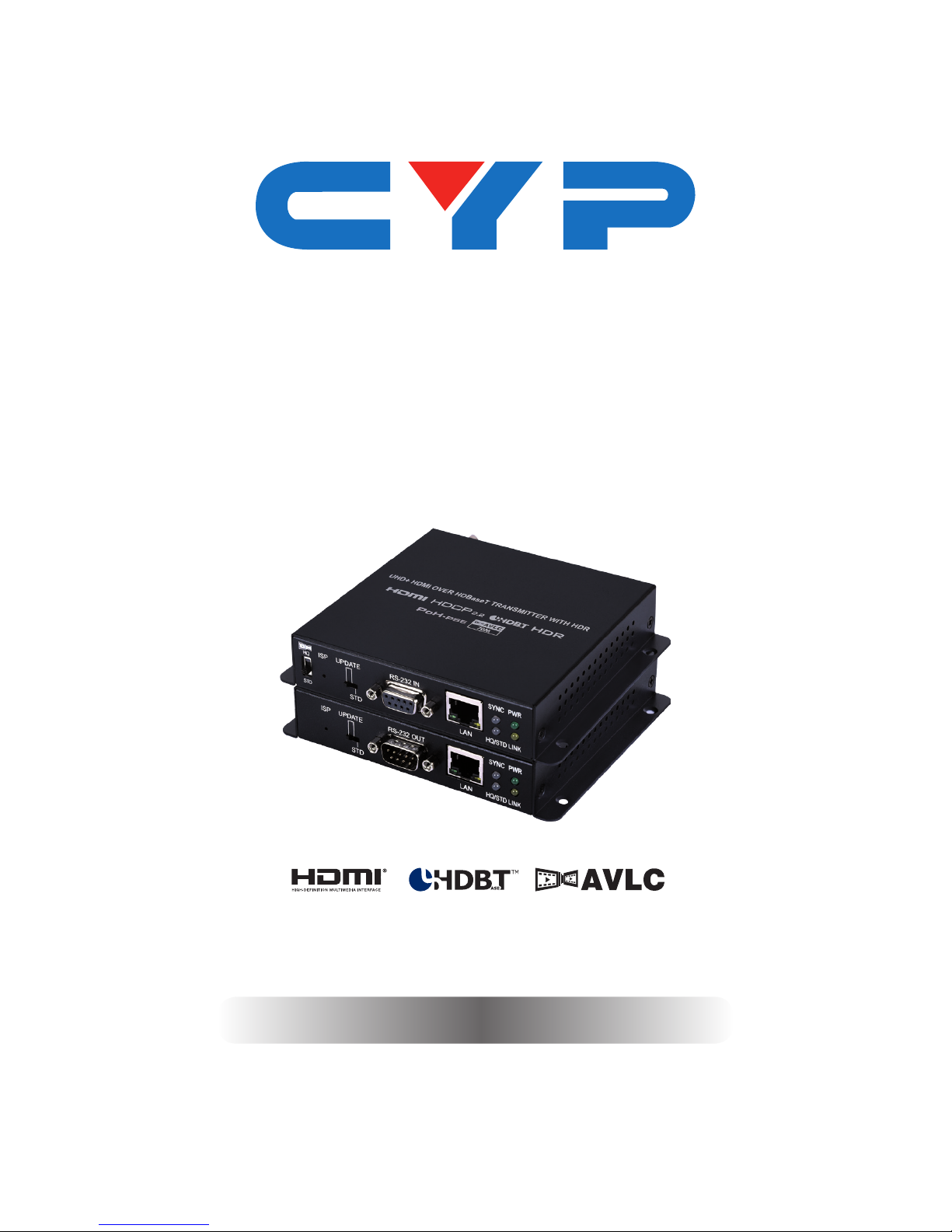
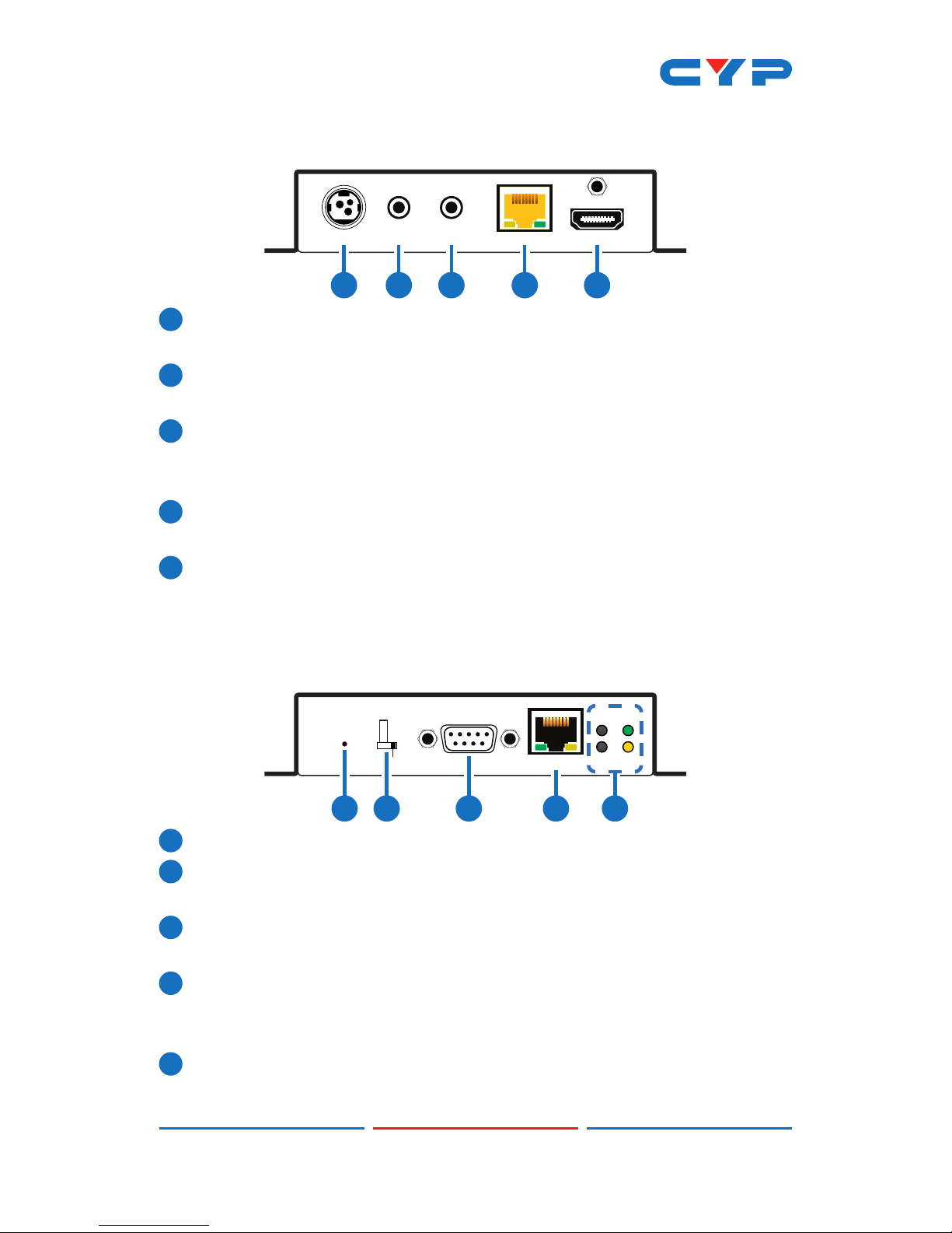
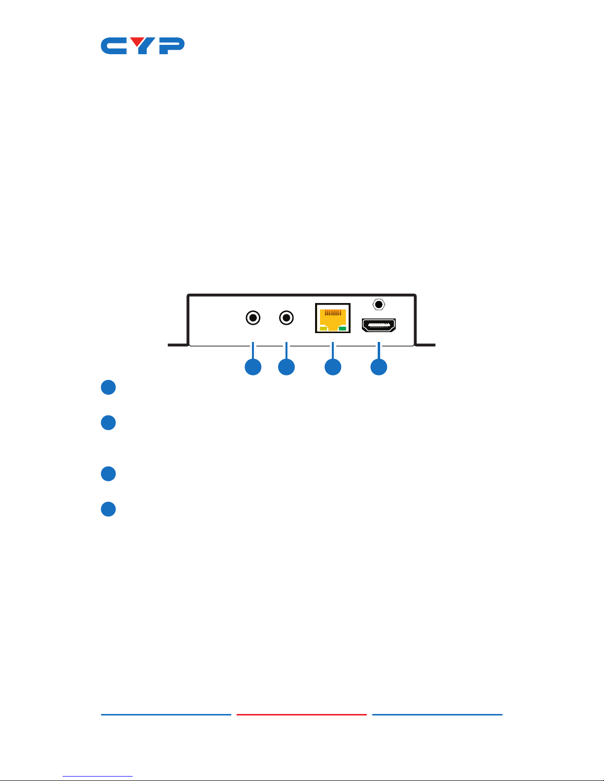
CYP CH-1527TXV User manual

CH-1527TXV & CH-1527RXV
4K UHD+HDMI over HDBaseT
Transmitter (PSE) & Receiver (PD)
Operation Manual
Operation Manual


DISCLAIMERS
The information in this manual has been carefully checked and
is believed to be accurate. Cypress Technology assumes no
responsibility for any infringements of patents or other rights of third
parties which may result from its use.
Cypress Technology assumes no responsibility for any inaccuracies
that may be contained in this document. Cypress also makes no
commitment to update or to keep current the information contained
in this document.
Cypress Technology reserves the right to make improvements to this
document and/or product at any time and without notice.
COPYRIGHT NOTICE
No part of this document may be reproduced, transmitted,
transcribed, stored in a retrieval system, or any of its part translated
into any language or computer le, in any form or by any means—
electronic, mechanical, magnetic, optical, chemical, manual, or
otherwise—without express written permission and consent from
Cypress Technology.
© Copyright 2018 by Cypress Technology.
All Rights Reserved.
TRADEMARK ACKNOWLEDGMENTS
All products or service names mentioned in this document may be
trademarks of the companies with which they are associated.

SAFETY PRECAUTIONS
Please read all instructions before attempting to unpack, install or
operate this equipment and before connecting the power supply.
Please keep the following in mind as you unpack and install this
equipment:
• Always follow basic safety precautions to reduce the risk of re,
electrical shock and injury to persons.
• To prevent re or shock hazard, do not expose the unit to rain,
moisture or install this product near water.
• Never spill liquid of any kind on or into this product.
• Never push an object of any kind into this product through any
openings or empty slots in the unit, as you may damage parts
inside the unit.
• Do not attach the power supply cabling to building surfaces.
• Use only the supplied power supply unit (PSU). Do not use the PSU
if it is damaged.
• Do not allow anything to rest on the power cabling or allow any
weight to be placed upon it or any person walk on it.
• To protect the unit from overheating, do not block any vents or
openings in the unit housing that provide ventilation and allow for
sufcient space for air to circulate around the unit.
REVISION HISTORY
VERSION NO. DATE SUMMARY OF CHANGE
RDV1 26/12/17 Preliminary release
VS1 09/01/18 Final technical review

CONTENTS
1. Introduction......................................................1
2. Applications.....................................................1
3. Package Contents ..........................................1
4. System Requirements......................................2
5. Features............................................................2
6. Operation Controls and Functions.................3
6.1 Transmitter's Front Panel ........................... 3
6.2 Transmitter's Rear Panel............................ 4
6.3 Receiver's Front Panel............................... 4
6.4 Receiver's Rear Panel ............................... 5
6.5 IR Pin Assignment ...................................... 6
6.6 RS-232 Protocol.......................................... 6
7. Connection Diagram ......................................7
8. Specications ..................................................8
8.1 Transmitter's Technical Specications..... 8
8.2 Receiver's Technical Specications........ 9
8.3 Video Specications............................... 10
8.4 Cable Specications .............................. 12
9. Acronyms .......................................................13

1
1. INTRODUCTION
This transmitter and receiver set is a great solution for extending UHD
video and audio as well as Ethernet and control via a single run of
Cat.5e/6/7 cable over distances up to 100 meters. This extender
set complies with the advanced HDCP 2.2 and HDMI 2.0 standards,
as well as supporting the legacy HDCP 1.x and HDMI 1.x standards.
Despite HDBaseT’s 10.2Gbps bandwidth limitation, 4K UHD HDMI video
sources, up to and including 4K@60Hz (4:4:4, 8-bit) as well as 10/12-
bit sources with HDR, are able to be processed and extended by the
use of AVLC (Adaptive Visually Lossless Compression) when needed.
Multiple data and control interfaces are also provided, including IR,
RS-232 and LAN connections. The Receiver (PD) is powered by 48V
PoH (Power over HDBaseT) provided by the Transmitter (PSE), allowing
for greater exibility within different installation scenarios.
2. APPLICATIONS
• Household entertainment sharing and control
• Lecture room display and control
• Showroom display and control
• Meeting room presentation and control
• Classroom display and control
3. PACKAGE CONTENTS
• 1×HDMI to Cat.5e/6/7 Transmitter (with LAN, IR & RS-232)
• 1×Cat.5e/6/7 to HDMI Receiver (with LAN, IR & RS-232)
• 1×48V/0.83A DC Power Adapter
• 1×3.5mm to IR Extender Cable
• 1×3.5mm to IR Blaster Cable
• 1×Operation Manual

2
4. SYSTEM REQUIREMENTS
• HDMI source equipment such as a media player, video game
console or set-top box.
• HDMI receiving equipment such as an HDTV, monitor or audio
amplier.
• The use of “Premium High Speed HDMI” cables, and industry
standard Cat.6, Cat.6a or Cat.7, is highly recommended.
5. FEATURES
• HDMI with HDR, 3D & 4K@60Hz support, DVI 1.0 compatible
• HDCP 2.2 and HDCP 1.x compliant
• Supports up to 4K UHD (18Gbps, 4K@50/60Hz 4:4:4, 8-bit) video input
• Supports output resolutions up to 4K@50/60Hz (4:4:4, 8-bit)
• Supports Deep Color input and output up to 12-bit
• Supports 10-bit and 12-bit HDR bypass
• Supports CEC bypass
• Simultaneous transmission of video, audio and data over a single
Cat.5e/6/7 cable up to 100m (328ft) at 1080p and 70m (246ft) at 4K
• Supported HDBaseT feature set: HD Video & Audio, 100BaseT
Ethernet, 48V PoH, and Control (Bidirectional IR/RS-232 pass-
through)
• Integrated AVLC (Adaptive Visually Lossless Compression) activates
when the bandwidth requirements of the source are beyond
10.2Gbps (340MHz) allowing for support of sources up to 18Gbps
(600MHz) with no loss of visual quality
• The AVLC function allows manual selection between High Quality
(Full bandwidth) mode and Standard mode (Lower bandwidth,
useful for longer cable runs with 4K sources)
• Supports standard IEEE 802.3 AT 48V PoH from Transmitter (PSE) to
Receiver (PD) (compatible Receivers only)
Note: The 48V PoH function is designed for powering compatible
Receiver units only. Non-PoH Receivers will need their own power
supply. Receivers from other brands may not be compatible.

3
6. OPERATION CONTROLS AND FUNCTIONS
6.1 Transmitter's Front Panel
LAN
RS-232 IN
STD
UPDATE
ISP
HQ
STD
LINK
PWR
SYNC
HQ/STD
1 2 3 4 5 6
1STD/HQ: This switch allows user to select which compression mode
to use when AVLC is active. HQ (High Quality) mode uses the
least amount of compression and provides the highest possible
visual quality (perceptually identical to the original). STD (Standard
Quality) mode applies additional signal reduction methods to
lower the bandwidth requirements of 4K sources further, improving
transmission reliability over longer cable runs at the cost of some
visual delity.
2ISP: This button is reserved for factory use only.
3STD/UPDATE: This switch is reserved for factory use only. The default
setting is “STD”.
4RS-232 IN: Connect to a PC, laptop or other serial control device
for the extension of RS-232 signals.
5LAN: Connect to an Ethernet supporting device or to your local
network, as appropriate, to extend the network to both ends of
the HDBaseT connection.
6SYNC LED: This LED will illuminate when a live input source is
detected.
HQ/STD LED: This LED will illuminate whenever the AVLC function
is active. A green LED indicates that AVLC is in HQ (High Quality)
mode. A red LED indicates that AVLC is in STD (Standard) mode.
POWER LED: This LED will illuminate to indicate the unit is on and
receiving power.
LINK LED: This LED will illuminate solidly when a live connection with
a compatible Receiver is active. The LED will blink with a regular
pattern if a Receiver is connected but there is not currently a live
signal. The LED will blink with an irregular pattern if a connection
error has occurred.

4
6.2 Transmitter's Rear Panel
HDMI INCAT5e/6/7 OUTDC 48V
IR2
EXTENDER
IR1
BLASTER
1 2 3 45
1DC 48V: Plug the 48V DC power adapter into this port and connect
it to an AC wall outlet for power.
2IR1 BLASTER: Connect to the provided IR Blaster to transmit IR
signals to devices within direct line-of-sight of the IR Blaster.
3IR2 EXTENDER: Connect to the provided IR Extender to extend
the IR control range of remotely located devices. Ensure that the
remote being used is within direct line-of-sight of the IR Extender.
4CAT5e/6/7 OUT: Connect to a compatible HDBaseT Receiver with
a single Cat.5e/6/7 cable for transmission of all data signals.
5HDMI IN: Connect to HDMI source equipment such as a media
player, game console or set-top box.
6.3 Receiver's Front Panel
LAN
RS-232 OUT
ISP
LINK
PWR
STD
UPDATE
SYNC
HQ/STD
1 2 3 4 5
1ISP: This button is reserved for factory use only.
2STD/UPDATE: This switch is reserved for factory use only. The default
setting is “STD”.
3RS-232 OUT: Connect to a serial controllable device for the
extension of RS-232 signals.
4LAN: Connect to an Ethernet supporting device or to your local
network, as appropriate, to extend the network to both ends of
the HDBaseT connection.
5SYNC LED: This LED will illuminate when a live input source is
detected.

5
HQ/STD LED: This LED will illuminate whenever the AVLC function
is active. A green LED indicates that AVLC is in HQ (High Quality)
mode. A red LED indicates that AVLC is in STD (Standard) mode.
POWER LED: This LED will illuminate to indicate the unit is on and
receiving power.
LINK LED: This LED will illuminate solidly when a live connection with
a compatible Receiver is active. The LED will blink with a regular
pattern if a Receiver is connected but there is not currently a live
signal. The LED will blink with an irregular pattern if a connection
error has occurred.
6.4 Receiver's Rear Panel
IR1
EXTENDER CAT5e/6/7 IN HDMI OUT
IR2
BLASTER
1 2 34
1IR2 BLASTER: Connect to the provided IR Blaster to transmit IR
signals to devices within direct line-of-sight of the IR Blaster.
2IR1 EXTENDER: Connect to the provided IR Extender to extend
the IR control range of remotely located devices. Ensure that the
remote being used is within direct line-of-sight of the IR Extender.
3CAT5e/6/7: Connect to a compatible HDBaseT Transmitter with a
single Cat.5e/6/7 cable for transmission of all data signals.
4HDMI OUT: Connect to an HDMI TV, monitor or amplier for digital
video and audio output.

6
6.5 IR Pin Assignment
3
1
2
Infrared
Power
Ground
IR Extender
3
1
2
IR Blaster Power
Infrared
NC
6.6 RS-232 Protocol
UNIT TERMINAL
Pin Pinout Pin Pinout
1 1
2TxD 2RxD
3RxD 3TxD
4 4
5GND 5GND
6 6
7 7
8 8
9 9

7
7. CONNECTION DIAGRAM
UHDTV
LAN
RS-232 IN
STD
UPDATE
ISP
HQ
STD
LINK
PWR
SYNC
HQ/STD
HDMI INCAT5e/6/7 OUTDC 48V
IR2
EXTENDER
IR1
BLASTER
IR1
EXTENDERCAT5e/6/7 IN HDMI OUT
IR2
BLASTER
LAN
RS-232 OUT
ISP
LINK
PWR
STD
UPDATE
SYNC
HQ/STD
7m3m 3m
60°
1.5m
60°
7m3m 3m
60°
1.5m
60°
Digital Media Player
Serial Equipped
Computer
Serial Controlled
Device
Wireless
Router
RS-232
RS-232
LAN
LAN
HDMI
Output
HDMI
Input
IR
IR
Cat.5e/6/7
Cable
Power Supply

8
8. SPECIFICATIONS
8.1 Transmitter's Technical Specications
HDMI Bandwidth 600MHz/18Gbps
HDBaseT Bandwidth 340MHz/10.2Gbps
Input Ports 1×HDMI
Output Ports 1×Cat.5e/6/7
Pass-through Ports 1×IR Extender [3.5mm]
1×IR Blaster [3.5mm]
1×RS-232 [9-pin D-sub]
1×LAN [RJ-45]
IR Frequency 30 - 50kHz (30 - 60kHz under ideal
conditions)
Baud Rate Up to 115200bps
Power Supply 48V/0.83A DC (US/EU standards, CE/
FCC/UL certied)
ESD Protection Human Body Model:
±8kV (Air Discharge)
±4kV (Contact Discharge)
Dimensions 128mm×25mm×108mm (W×H×D)
[Case Only]
128mm×25mm×117mm (W×H×D)
[All Inclusive]
Weight 385g
Chassis Material Metal
Silkscreen Color Black
Operating Temperature 0˚C - 40˚C/32˚F - 104˚F
Storage Temperature −20˚C - 60˚C/−4˚F - 140˚F
Relative Humidity 20 - 90% RH (Non-condensing)
Power Consumption 8.69W

9
8.2 Receiver's Technical Specications
HDMI Bandwidth 600MHz/18Gbps
HDBaseT Bandwidth 340MHz/10.2Gbps
Input Ports 1×Cat.5e/6/7
Output Ports 1×HDMI
Pass-through Ports 1×IR Extender [3.5mm]
1×IR Blaster [3.5mm]
1×RS-232 [9-pin D-sub]
1×LAN [RJ-45]
IR Frequency 30 - 50kHz (30 - 60kHz under ideal
conditions)
Baud Rate Up to 115200bps
Power Supply PoH
ESD Protection Human Body Model:
±8kV (Air Discharge)
±4kV (Contact Discharge)
Dimensions 128mm×25mm×108mm (W×H×D)
[Case Only]
128mm×25mm×117mm (W×H×D)
[All Inclusive]
Weight 386g
Chassis Material Metal
Silkscreen Color Black
Operating Temperature 0˚C - 40˚C/32˚F - 104˚F
Storage Temperature −20˚C - 60˚C/−4˚F - 140˚F
Relative Humidity 20 - 90% RH (Non-condensing)
Power Consumption 10W

10
8.3 Video Specications
Supported PC Resolutions (Hz)
HDMI
Input
HDMI
Output
640×480 60, 72, 75, 85
720×400 70, 85
800×600 56, 60, 72, 75, 85
1024×768 60, 70, 75, 85
1152×864 75
1280×720 50, 60
1280×768 60, 75, 85
1280×800 60, 60 (RB)
1280×960 60
1280×1024 60
1360×768 60
1366×768 60
1400×1050 60, 60 (RB)
1440×900 60, 60 (RB)
1600×900 60
1600×1200 60
1680×1050 60, 60 (RB)
1920×1080 60
1920×1200 60

11
Supported TV Resolutions (Hz)
HDMI
Input
HDMI
Output
720×480i 59.94, 60
720×576i 50
720×480p 59.94, 60
720×576p 50
1280×720p 50, 59.94, 60
1920×1080i 50, 59.94, 60
1920×1080p 50, 59.94, 60
1920×1080p 23.97, 24, 25, 29.97, 30
3840×2160p 24, 25, 30
4096×2160p 24, 25, 30
3840×2160p (YUV 4:2:0) 50, 60
3840×2160p 50, 60

12
8.4 Cable Specications
HDMI Cable
Length (meter)
1080p 4K
8-bit 12-bit 8-bit
Input 10 10 5
Output 10 5 5
Cat. Cable
Length (meter) 1080p 4K
Cat.5e 100 70
Cat.6 100 70
Cat.7 100 100
• Full HD Video (1080p)
- Up to 1080p@60Hz, 12-bit color
- Data rates lower than 5.3Gbps or below 225MHz TMDS clock
• Ultra HD Video (4K)
- 4K@24/25/30Hz & 4K@50/60Hz (YUV 4:2:0), 8-bit color
- 4K@50/60Hz (4:4:4, 8-bit) with AVLC active
- Data rates higher than 5.3Gbps or above 225MHz TMDS clock

13
9. ACRONYMS
ACRONYM COMPLETE TERM
AVLC Adaptive Visually Lossless Compression
Cat.5e Category 5 (enhanced) Cable
Cat.6 Category 6 Cable
Cat.7 Category 7 Cable
CEC Consumer Electronics Control
DVI Digital Visual Interface
HD High-Denition
HDCP High-bandwidth Digital Content Protection
HDMI High-Denition Multimedia Interface
HDR High Dynamic Range
IR Infrared
LAN Local Area Network
LPCM Linear Pulse-Code Modulation
PC Personal Computer
PD Powered Device
PoH Power over HDBaseT
PSE Power Sourcing Equipment
UHD Ultra-High-Denition


CYPRESS TECHNOLOGY CO., LTD.
www.cypress.com.tw
This manual suits for next models
1
Table of contents
Other CYP Transmitter manuals
Popular Transmitter manuals by other brands

YOKOGAWA
YOKOGAWA YTA Series user manual

ScreenBeam
ScreenBeam USB Transmitter 2 installation guide

Seip
Seip SKR2W quick start guide

Adtel
Adtel DigADTEL IPM installation instructions

Siemens
Siemens Sitrans LR250 instruction manual

BWI Eagle
BWI Eagle AIR-EAGLE SR PLUS 36-HH-4-VBR Product information bulletin