PBS SAFIR 5L User manual

PG 01-31
AUXILIARY POWER UNIT
SAFIR 5L
OPERATION AND ATTENDANCE MANUAL
ISSUED ON 4/2015
April 2015

2
SAFIR 5L
OPERATION AND ATTENDANCE MANUAL
PG 01-31
AUXILIARY POWER UNIT
SAFIR 5L
OPERATION AND SERVICE MANUAL
PG 01-31
Issued on April 2015
This document is the property of
PBS Velká Bíteš, a.s.
and it is illegal to copy, use or promulgate it as a whole or in parts for any other purpose
without prior written consent of the Manufacturer.

3
SAFIR 5L
OPERATION AND ATTENDANCE MANUAL
PG 01-31
LIST OF CHANGES AND CORRECTIONS
Change number Subject of change Validity Pages No. Performed by, date
L-KSS-3874
The parameters changing of the control box
based on the requirements from the
operation APU
From seriál
number APU
S5L 029
11, 59, 60
Bc. Tučková
17.2.2016

4
SAFIR 5L
OPERATION AND ATTENDANCE MANUAL
PG 01-31
LIST OF CONTENTS
LIST OF CHANGES AND CORRECTIONS.................................................................................................................... 3
LIST OF CONTENTS........................................................................................................................................................ 4
LIST OF ILLUSTRATIONS.............................................................................................................................................. 5
INTRODUCTION .............................................................................................................................................................. 6
1.BASIC TECHNICAL DATA .................................................................................................................................... 7
Auxiliary Power Unit......................................................................................................................................... 7
Fuel System ....................................................................................................................................................... 8
Oil System ......................................................................................................................................................... 9
Air System ....................................................................................................................................................... 10
Control and Regulation System ....................................................................................................................... 11
Actuating System............................................................................................................................................. 12
2.OPERATION INSTRUCTIONS ............................................................................................................................. 21
Pre-Start Preparation........................................................................................................................................ 21
APU Actuation................................................................................................................................................. 21
Engine Actuation ............................................................................................................................................. 21
APU Cold Turn................................................................................................................................................ 21
APU Switch off................................................................................................................................................ 21
Monitoring and Signaling Equipment.............................................................................................................. 21
3.OPERATIVE LIMITS ............................................................................................................................................. 22
Actuation Repeatability ................................................................................................................................... 22
Low Temperature Operation............................................................................................................................ 22
Power Supplies ................................................................................................................................................ 22
Compressor Protection..................................................................................................................................... 22
Control System Protection ............................................................................................................................... 22
Air Intake Limits (in 100 % Mode) ................................................................................................................ 22
Permissible Overload with APU Switched off ............................................................................................... 23
Fluids in Use.................................................................................................................................................... 23
APU Actuation in flight................................................................................................................................... 24
Other Limits..................................................................................................................................................... 24
4.SERVICE INSTRUCTIONS ................................................................................................................................... 25
General Survey ................................................................................................................................................ 25
Assembly and Operation Instructions.............................................................................................................. 25
Instructions for Replacement of APU In-Operation ........................................................................................ 27
Activation ........................................................................................................................................................ 27
Definitions of Periodic Work........................................................................................................................... 28
Time-limits of Activity – Technical Resource................................................................................................. 30
Scope of Periodic Work................................................................................................................................... 30
Checking Techniques....................................................................................................................................... 33
5.DEWAXING AND PRESERVATION IN OPERATION .................................................................................... 51
Dewaxing – on Delivery from the Manufacturer (replacement parts, after repair, etc.) .................................. 51
Dewaxing after 3 Months Preservation, Performed In-Operation. .................................................................. 51
First Actuation of APU.................................................................................................................................... 51
Preservation Valid for 30 Days........................................................................................................................ 51
Internal Preservation Valid for 3 Months +18-9 Days ........................................................................................ 51
Preservation Valid for 1 Year .......................................................................................................................... 52
Preservation and Packing for Shipping Devices to the Manufacturer............................................................. 52
6.DEFECTS AND TROUBLESHOOTING.............................................................................................................. 53
General Survey ................................................................................................................................................ 53
Explanatory Notes to the Schematic Diagrams................................................................................................ 54
List of Algorithms for APU Function Monitoring and Troubleshooting......................................................... 55

5
SAFIR 5L
OPERATION AND ATTENDANCE MANUAL
PG 01-31
APPENDIX:
Pages
APPENDIX No.1 Technical and operating manual of Control Box LUN 3594.04 34
APPENDIX No.2 Dimensional Drawings 9
Auxiliary Power Unit SAFIR 5L P/N 490100.02
Block of Filter and Servo P/N 490740.01
Fuel Pump P/N 490720.01
Return Fuel Filter LUN 7616-8
Oil Tank P/N 490620.03
Oil Pump LUN 6320-8
Anti-surge valve P/N 490330.03
Ignition exciter P/N 81550.01
Control box LUN 3594.04
APPENDIX No.3 Auxiliary Power Unit SAFIR 5L – Interface Control Document (ICD) 2
LIST OF ILLUSTRATIONS
Fig.
No. Page
1. Fuel System Diagram 13
2. Oil System Diagram 14
3. Air System Diagram 15
4. Wiring Diagram with control box LUN 3594.04 16
5. APU Function Flow Chart 17
6. Timing Behavior of APU Start and Operation 18
7. Time Behavior of APU Protective Circuits 19
8. Kinematic Diagram of APU Gear Box 20
9. Oil Pump LUN 6320-8 41
10. Broken-out Section of APU Air Generator 42
11. Permissible Defects of the Combustion Chamber 43
12. Sectional View of the Block of Filter and Servo 490740.01 44
13. Sectional View of the Return Fuel Filter LUN 7616-8 45
14. Broken-out Section of the Oil Filter 490131.01 46
15. Oil Tank 490620.03 47
16. Ignition Plug 85500.11 instalation 48
17. Interconnecting conductor 490510.01 48
18. Speed Transmitter LUN 1326.03-8 49
19. Electric-Starter 490110.01 50

6
SAFIR 5L
OPERATION AND ATTENDANCE MANUAL
PG 01-31
INTRODUCTION
This Manual is intended for technicians and mechanics, who support the operation of the Auxiliary Power Unit SAFIR
5L.
It contains instructions for all work that will occur during the APU operation in the time till the complete overhaul.
The adherence to these instructions is the prerequisite of achieving a reliable operation and endurance of APU. The
minute command of these instructions is, therefore, in the interest of the operating organization.
The non-observance of these instructions during operation or troubleshooting, which is not allowed by these
instructions, divest the user of warranty and the Manufacturer is not liable for possible damages arising thereof.

7
SAFIR 5L
OPERATION AND ATTENDANCE MANUAL
PG 01-31
1. BASIC TECHNICAL DATA
Auxiliary Power Unit
Identification, type: SAFIR 5L
Description: Turbo-reactive engine with automatic control and air
outtake from compressor
Compressor: single stage, radial
Technical parameters for standard conditions: See article 1.4
Combustion chamber:
Turbine:
Operating speed (100%):
Idling speed (89%):
APU weight without exhaust pipe
Weight with accessories
annular
two- stage, axial flow
51 900 rpm
46 400 rpm
31 kg
42 kg
Fuel: T1,T2,ТS-1
according to:
GOST 10227-86
JET A, JET A-1, JET B
according to:
- DERD 2494 (Brit. Specification)
- MIL-T-83133D (US Specification)
JET A-1
according to:
- DEF STAN 91-91
- AFQRJOS
- STAS 3754-77
JP 8,
according to:
- DERD 2453 (British Specification)
- MIL-T-83133D (US Specification)
RP-1,
according to:
(GB 6537-86)
RP-2,
according to:
(GB1788-79
)
RP-3,
according to:
(GB 6537-86)
Cleanness the fuel must conform to the class 10-11 according to GOST 17216-71 or 7 - according to NAS 1638
Oil: AEROSHELL TURBINE OIL 500 a 560,
according to:
MIL-L-23699D
MOBIL JET OIL II,
according to:
MIL-L-23699D
IPM10,
according to:
ОSТ38.01294-83
MS – 8P,
according to:
ОSТ38-01163-78
B3-V ,
according to:
TU38-101-295-85
HP-8B,
according to:
GB 439-1990
Cleanness the oil must conform to the class 14 according to GOST 17216-71 or 10 - according to NAS 1638
Warning: The using of other fuels and oils with the APU manufacturer permission only!
Power supply: Accumulator 24 V, 25 Аh
(charged at least to 75 % of its nominal capacity)
Number of actuations per 1 charge of the accumulator: at least 4
Operation voltage range: 23,5 – 28,5 V
Height for start of APU and engine and
air intake for the airplane air conditioning: 26 500 ft (8 000 m)
Ambient temperature range for reliable function of
APU:
-60 °С+60 С(-76 F +140 F), (with the restrictions
under article 3.2)
Time of APU operation in maximum mode (100%): 120 min. max.
Repeatability of APU actuation and engine see article 3.1
Fuel consumption: 70 kg/hour max.
Oil consumption: 150 cm3/ hour max.

8
SAFIR 5L
OPERATION AND ATTENDANCE MANUAL
PG 01-31
Fuel System
Description:
flow rate:
Max. pressure
low-pressure, with constant input flow rate, with twelve
bypass nozzles and throttled output
130±5 l.hour-1
1,3±0,1 MPа
Working fuel temperature -40 ÷ +60 °C
Block of Filter and Servo: 490740.01
-filter efficiency 12
m
-signaling of clogging switches on, when pressure loss in the filter element
reaches 359 kPа
-filter relief valve turns on, when pressure loss in the filter element reaches
5512 kPа
-electromagnetic valve opened when energized, max. current consumption 1,5 А
-servo-operated valve current consumption 0-150 mА
modulation 250 Hz – 500 mV
-non-return valve opens when pressure exceeds 10 kPа
-thermoregulator 32 С(89.618 F)
-air-relief valve opens at pressure amounting to 20 kPа
-slide-valve adjustment at 10010 kPа
Fuel pump: 490720.01
-type single stage, gear-type
-filter 63
m
-delivered quantity 130±5 l.hour-1 (depended on operation mode)
-pressure 1,3±0,1 MPа
Fuel - oil exchanger: Tubular
Fuel nozzle: bypass (with fuel bypassing)
-number of nozzles: 12
Fuel ramp drainage valve: DV-1
-closes at fuel pressure amounting to: 15+10 kPа
Combustion chamber drainage valve: DV-2
-closes at air pressure amounting to: 36+2-8 kPа
Return fuel filter: LUN 7616-8
-filter efficiency 12
m
-bypass set to 305 kPа

9
SAFIR 5L
OPERATION AND ATTENDANCE MANUAL
PG 01-31
Oil System
Description: autonomous, directly deaeration with open circulation
-flow rate 45 l.hour-1
-oil pressure 210 kPаmax.
-minimum oil pressure
-operating oil temperature
885 kPа
-40 ÷ +140 °C (-40÷284 F)
Oil tank: 490620.03
-total volume 2 l
-"MAX." level mark volume 1,3 l
-”MIN” level mark volume 0,8 l
-level indicator Glass pipe
-relief valve opens at pressure amounting to 40+5-10 kPа
-drain plug with magnet
-filler neck with quick-closing valve and screen
filter efficiency 200
m
-fuel - oil exchanger tubular
-output filter, filter efficiency 80
m
Oil pump: LUN 6320-8
-description single stage
-drive from APU gear
-change-over ratio 1:7
Oil filter: 490131.01
-filter efficiency 35
m
-differential pressure indicator
LUN 1491.22
switches on, when the filter element losses reach 405kPa
-cleaner relief valve opens, when pressure losses in the filter element reach
555 kPа
-pressure switch of oil filter
LUN 6751-8
switches on, when pressure decreases to 805 kPа
-electromagnetic valve opens when energized, current consumption
with voltage 27 +1 VDC < 1,5 А
Electromagnetic valve: 486611.01
-function opens when under voltage (alive)
-current consumption < 350 mА
Electromagnetic fuel valve: LUN 2475-8
-function opens when under voltage (alive)
-current consumption < 1,5А.

10
SAFIR 5L
OPERATION AND ATTENDANCE MANUAL
PG 01-31
Air System
Carakteristic
Air parameters behind anti-stall bleed valve at 100 %
speed mode (for ISA, H=0m)
Output
-air flow ≥1920 kg.h-1
-air presure ≥348 kPa
-warming of the air in the compressor
-air inlet temperature
190 С(374 F)
-60 ÷ +60 С(-75.982 °F ÷ +140,018 °F)
Venturi tube:
-purpose
33 mm
APU protection
(part of the anti-stall bleed valve, restricting the air
quantity from the compressor and protect turbine
overheating)
Anti-surge valve 490330.03
-closing initiation at the Venturi tube over-pressure
of
55±5 kPа
-opening initiation at the Venturi tube over-pressure
of
70±5 kPа
visor in the output throat of the anti-stall bleed valve
27 mm

11
SAFIR 5L
OPERATION AND ATTENDANCE MANUAL
PG 01-31
Control and Regulation System
Description: electronic
Speed transmitter: LUN 1326.03-8
-purpose produces the input signal for electronic control
-type electromagnetic
-output voltage 1 V on 2145 Hz 5 %
-location on the APU gearbox
-tooth-wheel with circumferential holes number of holes: 36
-conversion ratio rpm / Hz 11,668
Temperature Transmitter
-purpose
-type
-number off transmitter
LUN 1371.01-8
produces the input signal for electronic control
Thermocouple CHROMEL-ALUMEL
3
Control box: LUN 3594.04
-purpose - controls the APU speed according to the mode selected
- controls the function of electric accessories
- type
- performs the APU closing
- digital
-preset modes - full operating speed 100 % 51 900 rpm
- idling speed 89 % 46 400 rpm
-APU protections (levels of setup) - maximum speed 109 % 56 660 rpm
- sub-speed 79 % 41 200 rpm
- closing during actuation, when the
exhaust gas temperature does not reach
150 С(302 F) within
13 sec.
- closing of APU during actuation, when
sub-speed (70 %) is not reached within
35 sec.
- high temperature of the exhaust gases is
signalized, when the temperature reaches
850± 15 С
(1562±59 F)
- In case of exceeding the set exhaust gases
temperature - the control box will perform
decrease of turbine speed until reaching of
the set temperature of the exhaust gases.
800 ± 15 °C
(1472±59 F)
Signaling on the control panel in the pilot’s
compartment which will not cause closing of APU:
- rotation speed 89 %
- rotation speed 100 %
-high gas temperature
-clogging of the oil filter
-clogging of the fuel filter
Detailed description of technical characteristic and operating work of the Control Box LUN 3594.04 see Enclosure
No. 1) – document PRP-2011-602-02-801, Technical and operating manual.

12
SAFIR 5L
OPERATION AND ATTENDANCE MANUAL
PG 01-31
Actuating System
Ignition exciter P/N 81550.01
type high-energy
nominal voltage 28 V
output voltage 2,5-3 kV
number of outputs (for ignition plug) 1
Type of ignition plug
The interconnecting conductor (length1100mm)
85500.11
490510.01
Electric-starter
type 490110.01
output on 4600 rpm 1,25 kW
maximum terminal voltage 26 V (see article 3.10)
maximum speed 28 800 rpm
change-over ratio 1:1,96
clutch overrunning, centrifugal, torque - slip
slip moment 10+0,5 Nm
13
SAFIR 5L
OPERATION AND ATTENDANCE MANUAL
PG 01-31
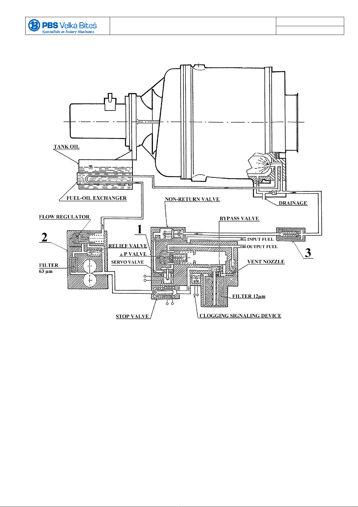
1 – BLOCK OF FILTER AND SERVO 490740.01
2 – ELECTRIC FUEL PUMP 490720.01
3 – RETURN FUEL FILTER LUN 7616-8
Fig.1. Fuel System Diagram

14
SAFIR 5L
OPERATION AND ATTENDANCE MANUAL
PG 01-31
1 – OIL TANK 490620.03
2 – OIL PUMP LUN 6320-8
3 – OIL FILTER 490131.01
4 – ELECTROMAGNETIC VALVE 486611.01
5 – ELECTROMAGNETIC FUEL VALVE LUN 2475-8
Fig.2. Oil System Diagram
FILTER
80 μm

15
SAFIR 5L
OPERATION AND ATTENDANCE MANUAL
PG 01-31
1 – ANTI-SURGE VALVE 490330.03
Fig.3. Air System Diagram
ø33
Bleed nozzle
ø27

16
SAFIR 5L
OPERATION AND ATTENDANCE MANUAL
PG 01-31
Fig.4 Wiring Diagram with Control Box LUN 3594.04

17
SAFIR 5L
OPERATION AND ATTENDANCE MANUAL
PG 01-31
Fig. 5. APU Function Flow Chart
APU - Auxiliary Power Unit SAFIR 5L
FP - Fuel Pump
EV1 - Electromagnetic Fuel Valve of Filter and Servo Block
EV2 - Electromagnetic Valve of Oil Filter
EV3 - Electromagnetic Valve of Oil Tank - air vent.
EV4 - Electromagnetic Valve of Oil Drain
ES - Electric Starter
EU - Ignition Exciter
ATS - Pneumatic Starter
TP - Speed Transmitter
EC -Control Box
EV1, EV2, EV3, EV4 - open
FP, ES, EU - when nergized
Timing circuit
2 – 10 – 13 – 35 s - actuated
APU Start up
After 2s Control Systém
does not have adequate
signal from TP
Sub-speed reached in 35s ES, EU
disconected from thepower supply
Timing 13 s
reached at the exhaust
gases
temperature˂150°C
(
302°F
)
Timing 35
s finished before
reaching
sub-s
p
eed
The APU speed reached
idlin
g
APU CUT – OFF
by pilot
Inadequate oil pressure
after 30s
of APU operation
By switching
off the svitch
„DELAY
STOP“
Decrease the rotational
speed at idle and two
minutes waiting at idle
in order to cool the
turbine.
EV1, EV2, FP - disconnected from power supply
Timing 180s - actuated
After 180s EV3, EV4 switched off
from the power supply
By switching off the svitch
„EMERGENCI STOP“
The APU reached
The operating speed
APU CUT – OFF
by automatic protection system
Two brakers and
switch switched
RUN
Push the
START BUTON

18
SAFIR 5L
OPERATION AND ATTENDANCE MANUAL
PG 01-31
rpm
% min-1
110
100
90
80
70
60
50
40
30
20
10
0
56650
51900
46400
41200
0 5 10 15 20 25 30 35 40 45 50 100 200 300 400 500 600
Times
1. Initiation of the start APU after switching on of the power supply circuit by switching on the relevant breakers and
switches "RUN" and push down the "START BUTON"
2. Ignition of fuel in the combustion chamber
3. Start of electronic control function
4. Attainment of sub-speed (80 %)
5. Attainment of idling (89 %)
6. Reaching operating speed (100 %), cold and hot start of the main engines
7. APU cut-off by pilot, after finishing the main engine starting, by switching off the switch „DELAY STOP“
Reaching idle (89 %), and two minutes waiting at idle in order to cool the turbine
8. Automatic shutdown of the APU running.
9. Stop the APU rotor
Minimum total running time APU which is necessary for the successful launch of the two main engines is five minutes.
Immediate interruption of the function APU is possible to switching off the switch "EMERGENCY STOP"
APU start, operation and switch off
permissible range of the speed APU
Fig. 6. Timing Behavior of APU Start and Operation
2
3
4
5
6 7
8 9
10
1

19
SAFIR 5L
OPERATION AND ATTENDANCE MANUAL
PG 01-31
1. APU switch off resulting from inadequate signal level of the speed transmitter
or from a speed transmitter circuit failure
2. APU switch off resulting from failure to achieve exhaust gas temperature of 150 oC (302 oF)
(no ignition of the combustion chamber) within 13 s after the start
3. APU switch off resulting from failure to achieve APU sub-speed within 35 s
4. APU switch off after 35 s resulting from low oil pressure
5. APU switch off resulting from reaching over-speed
6. APU switch off resulting from decrease of APU speed bellow the lowest permissible value
7. Decrease of oil pressure during APU operation after 35 s timing
8. End of pressure switch bridging (14 s) and interruption of the APU function resulting from low oil pressure
APU start, operation and switch off in the Idling Mode
APU start, operation and switch off in the 100 % Speed Mode
permissible range of speed
Fig. 7. Timing Behavior of APU Protective Circuits

20
SAFIR 5L
OPERATION AND ATTENDANCE MANUAL
PG 01-31
1. Electrоstarter Conversion ratio 1:1,96
2. Oil Pump Conversion ratio 1:7
Fig. 8. Kinematic Diagram of APU Gear Box
Table of contents
Popular Portable Generator manuals by other brands


Champion
Champion 42436 Owner's manual & operating instructions

Generac Power Systems
Generac Power Systems Mobile Power MMG185 Specifications

IPC
IPC SG-70 instruction manual

Olympus
Olympus OME-L200 instructions

Koshin America Corporation
Koshin America Corporation GEH-7200EX Insert

Global
Global 8550-SD operating manual


