PCE Health and Fitness PCE-OVM 3D User manual
PCE Americas Inc.
1201 Jupiter Park Drive
Suite 8
Jupiter
FL-33458
USA
From outside US: +1
Tel: (561) 320-9162
Fax: (561) 320-9176
info@pce-americas.com
PCE Instruments UK Ltd.
Unit 11
Southpoint Business Park
Ensign way
Hampshire / Southampton
United Kingdom, SO31 4RF
From outside UK: +44
Tel: (0) 2380 98703 0
Fax: (0) 2380 98703 9
info@pce-instruments.co.uk
www.pce-instruments.com/english
www.pce-instruments.com
User Manual
PCE-OVM 3D
Version 1.2
Date of creation: 04.11.2014
Last change: 06.11.2020

2
Contents
Contents.............................................................................................................................................................. 2
1 Introduction .................................................................................................................................................. 4
1.1 Symbols Used.................................................................................................................... 4
2 Safety................................................................................................................................................................ 5
2.1 Intended Use..................................................................................................................... 5
2.2 Unintended Use ................................................................................................................ 5
2.3 Ambient Conditions for Safe Operation........................................................................... 5
2.4 Ambient Conditions for Storage and Transport.............................................................. 5
2.5 Hazard and Warning Notes............................................................................................... 5
2.6 Approved Personnel ......................................................................................................... 6
2.7 Liability Exclusion............................................................................................................. 6
3 Product Description ................................................................................................................................... 7
3.1 General Description .......................................................................................................... 7
3.2 Assemblies and Functional Elements .............................................................................. 7
3.3 Scope of Delivery .............................................................................................................. 8
4 Commissioning............................................................................................................................................. 9
4.1 Unpacking ......................................................................................................................... 9
4.2 Mounting the Monitor Stand ............................................................................................ 9
4.3 Setup ................................................................................................................................. 9
4.4 Electrical Connection...................................................................................................... 11
5 Operation......................................................................................................................................................12
5.1 Switching On................................................................................................................... 12
5.2 Adjusting the Monitor ..................................................................................................... 12
5.3 Adjusting the Focus ........................................................................................................ 12
5.4 System Settings .............................................................................................................. 12
5.5 Menu................................................................................................................................ 14
5.6 Screen Shot / Still Image ................................................................................................ 18
5.7 Working with 3D.............................................................................................................. 18
6 Monitor..........................................................................................................................................................19
6.1 Safety Instructions.......................................................................................................... 19
6.2 Connections .................................................................................................................... 19
6.3 Operation and Settings................................................................................................... 20
6.4 Monitor Menu.................................................................................................................. 20
7 Cleaning / Maintenance..........................................................................................................................22
7.1 Cleaning the Lighting...................................................................................................... 22
7.2 Cleaning/Replacing the Protective Glass....................................................................... 22
7.3 Removing the Cable from the Cable Duct / Guiding It into the Cable Duct.................. 22
7.4 Spare Parts...................................................................................................................... 23
8 Troubleshooting ........................................................................................................................................24
9 Technical Data............................................................................................................................................26

3
9.1 Head (Incl. Support Arm)................................................................................................ 26
9.2 Monitor............................................................................................................................ 27
10 Guarantee ..................................................................................................................................................28
11 Disposal Instructions ............................................................................................................................29

4
1Introduction
1.1 Symbols Used
This manual contains symbols also found on the appliance itself with the following meaning:
Danger
Immediate risk of injury. Consult accompanying documents.
Electrical Current
This indicates a risk of injury due to electrical current.
Caution
Risk of damage to the unit if the instruction is not followed.
Notice
A general notice that improves and eases use.
The device complies with applicable EU directives.
Within the EU, this device is subject to the provisions of the directive 2002/96/EC (WEEE
directive).
►List, special attention
• List
- List
⇒Instruction / required action / entry / order of tasks:
You are prompted to perform the specified action in the given order.
Result of an action / reaction of the device / reaction of the program:
The device or program responds to your action or because a particular event occurred.
Other symbols are explained when displayed.

5
2Safety
2.1 Intended Use
The system is used for digital stereo magnification in 2D and 3D in real time and for documentation.
2.2 Unintended Use
Only spare parts and accessories supplied or authorized by PCE Instruments may be used with this product. If other
spare parts or accessories are used, this could have a detrimental effect on the safety of the device, increase the risk
of serious injury, and lead to damage to the environment or the device itself.
2.3 Ambient Conditions for Safe Operation
The appliance should only be operated:
•indoors
•up to 2,000 meters (6,562 ft) above sea level
•at an ambient temperature of 5 –35 ºC [41 –95 ºF] *)
•at a maximum relative humidity of 80 % at 31 ºC [87.8 ºF], linear reduction up to 50 % relative humidity at 35 ºC [95 ºF] *)
•with mains electricity supply provided that the voltage fluctuation is within 10 % of the rated value
•with Pollution Degree 2
•with Overvoltage Category II
*) The unit can be used at a temperature of 5 –30 ºC [41 –86 ºF] and at a humidity of up to 80 %. At
temperatures of
31 –35 ºC [87.8 –95 ºF], the humidity must reduce proportionally to ensure that the unit can be operated (e.g. at
33 ºC [91.4 ºF] = 65 % humidity, at 35 ºC [95 ºF] = 50 % humidity). The unit should not be operated at
temperatures above 35 ºC [95 ºF].
2.4 Ambient Conditions for Storage and Transport
For storage and transport, the following ambient conditions must be maintained:
•Ambient temperature of -20 –+60 ºC [-4 –+140 ºF]
•Maximum relative humidity of 80 %
2.5 Hazard and Warning Notes
2.5.1 General Information
► If the unit is not operated according to this instruction manual, the intended protection cannot be
ensured anymore.
► The unit should only be operated using a mains cable with a country-specific plug system. Any
modification required should only be carried out by an electrician.
► The unit should only be operated if the data on the type plate corresponds with the data of the regional
mains voltage.
► The unit should only be plugged into earthed sockets.
► The mains socket should be easily accessible.
► Disconnect the unit from the mains before working on electrical parts.
► Regularly check connecting cables (such as power cables), hoses, and housing (for example, the
control panel) for damage (for example, kinks, tears, porosity) or deterioration due to aging. Do not
operate units with damaged connection cables, hoses, or housing parts, or other defects.
► Damaged equipment must be taken out of service immediately. Disconnect from mains and secure
against being switched on again. Send the device in for repair.
► Operate the equipment only under supervision.
► Observe national accident prevention regulations.
► It is the responsibility of the operator that national regulations during operation and regarding a

6
repeated safety inspection of electrical equipment are complied with. For Germany, these are the
regulation 3 by DGUV (German Statutory Accident Insurance) in relation with VDE (Association for
Electrical & Electronic Technology) 0701-0702.
2.5.2 Specific Information
►Do not look into the lighting.
►As with all optical magnification systems, working with the system for long periods of time can lead to
symptoms of fatigue. Take breaks regularly.
►The 3D glasses do not replace protective eye equipment in any way.
Further safety instructions for the monitor can be found in Chapter 6.
2.6 Approved Personnel
The device may only be operated and maintained by trained personnel.
Repairs that are not specified in this operating manual should only be carried out by an electrician.
2.7 Liability Exclusion
PCE Instruments is not liable for claims for compensation or claims under guarantee if:
► the product is used for purposes other than those stated in the operating instructions.
► the product is modified in any way –apart from modifications described in the operating instructions.
► the product has not been repaired by a specialist firm or original PCE replacement parts have not been
used.
► there is continued use of the product despite obvious safety defects or damage.
► the product has been subjected to mechanical knocks or has been dropped.

7
3Product Description
3.1 General Description
The PCE-OVM 3D system consists of a head with two cameras, a lighting, an image processing unit, and a 3D-
capable monitor including two pairs of 3D glasses.
For easy operation, the head is mounted on an adjustable support arm.
3.2 Assemblies and Functional Elements
Fig. 1
1 Head 9Tool for clamping force adjustment
2 Supporting arm with base (Allen key)
3 Monitor 10 Foot switch
4 power supply 11 Mouse
5 Monitor power supply 12 Desk pad (not included)
6 Height adjustment (focusing) 13 3D glasses
7 On/off switch 14 USB memory stick
8 On/off switch monitor

8
Connections
20 Power supply
21 HDMI output
22 USB port for USB memory stick
23 Foot switch
24 USB port for mouse
25 Network
3.3 Scope of Delivery
3.3.1 PCE-OVM 3D
1 PCE-OVM 3D head with power supply unit and power cord
1 support arm with cable and base with universal clamp
1 3D-capable monitor with power supply unit and power cord
2 pairs of 3D glasses
1 USB memory stick
1 mouse
1 foot switch
1 quick start guide “Getting Started”
on the optional accessories, please see chapter 7.)

9
4Commissioning
4.1 Unpacking
⇒Remove the device and accessories from the shipping box.
⇒Check the delivery for completeness (compare with the scope of
delivery).
4.2 Mounting the Monitor Stand
⇒ Place a soft pad on a flat surface.
⇒ Place the monitor on the pad, the screen facing down.
⇒ Remove the protective film from the stand.
⇒ Attach the supplied stand to the monitor support.
Fig. 3
4.3 Setup
Select a workspace with sufficient lighting for the installation of the PCE-OVM 3D system. If fluorescent light is used,
it may be necessary to reduce the light emission. Reflections of extraneous light on the object may result in
interferences.
⇒Place the desk pad (12, Fig. 1) on the working table.
The surface structure and color of the desk pad have been selected to reduce irritation to the eye,
which could occur with a structured surface.
4.3.1 Mounting the Support Arm
The support arm should preferably be mounted on the back or side of the
table top, at least 400 mm (15.75 in) away from the front edge.
This makes it possible to optimally utilize the entire swiveling range of the
support arm.
⇒ Mount the base with the universal clamp on the back or side of the work table (Fig. 4).
The universal clamp is suitable for tables with a slab thickness of 18 –74 mm (0.71 –2.91
in). Refer to chapter 3.4 for more mounting options.
⇒ Insert the support arm (2) into the base. Make sure that the red plastic disc (30) is placed
between the base and the support arm.
The power supply cable for the head is integrated into the support arm; the
cables for the mouse, foot switch, and monitor have already been guided
through the cable channel on the back of the support arm.
⇒Place the mouse (11, Fig. 1) next to the desk pad.
⇒Place the foot switch (10, Fig. 1) under the table and insert the cable for
the foot
switch into the foot switch.
Fig. 6

10
4.3.2 Mounting the Head
Four washers are needed for mounting the head (see Fig. 7).
Three small washers (golden/black/golden) have already been threaded
onto the fastening screw (31) in the correct sequence. The large washer is
attached to the head with an adhesive strip with a red end.
⇒ Remove the adhesive tape with the red end.
⇒ Loosen the fastening screw (31) on the support arm.
⇒ Attach the fastening screw with all three small washers through the
adapter of
the head.
⇒ Make sure that the three small washers (golden/black/golden) and the
large
washer are in the correct order as shown in the figure.
⇒ Insert the adapter with the fastening screw and tighten the fastening screw until
the head no longer tilts downward.
4.3.3 Positioning the Monitor
⇒ Position the monitor so that it is directly in the field of view. The distance to the observer should be between 50
and 70 cm (19.69 –27.56 in).
⇒ Align the monitor (tilt, rotate using stand) so that the viewing direction is perpendicular to the monitor in all
planes (Fig. 8/9).
Fig. 8 Fig. 9
4.3.4 Adjusting the Clamping Force
In order to achieve a stable position of the head, the clamping forces of the three joints can be adjusted individually.
• Support arm
-Fasten the screw at the head (32).
-Middle clamping screw (33)
-Clamp screw on base part (34)
• Swiveling the head right/left
-Clamping screw (35) with the included tool (9, Fig. 1)
• Height adjustment
-Clamping screw (36) with the included tool (9, Fig. 1)

11
4.4 Electrical Connection
Several plugs and related connector sockets are marked with a color coding. When connecting the
components, make sure that the color coding matches. Improperly connected components can be damaged
by too high voltage.
4.4.1 Connections on the Head
The cables are connected at the back of the head.
⇒ Monitor cable ==> HDMI connection (21).
Plug the HDMI cable (36) into the retaining clip and then plug it straight
into the
socket.
⇒ Foot switch cable ==> connection (23).
⇒ Mouse cable ==> connection (24).
⇒USB memory stick ==> connection (22). Fig. 12 a
⇒ Network extension cable ==> connection (25).
⇒ Power supply of the head (integrated into the support arm) ==> connection
(20).
4.4.2 PCE-OVM 3D Head Power Supply
The PCE-OVM 3D power supply (4, Fig. 1) has a cable with an angled jack plug (37). Fig. 12b
⇒ Plug the jack into the socket at the cable of the power supply, which protrudes at the base of the
support arm.
Make sure that the color coding of the connection cable and socket matches.
Never plug the jack plug into the connection for the foot switch (23, Fig. 12).
This will destroy the head.
Fig. 13
⇒Insert the power cord into the power supply unit and into the building wall socket.
4.4.3 Connecting the Monitor
⇒Monitor cable ==> DVI input of the monitor (41).
⇒Secure plug with integrated screws.
⇒Power supply ==> DC 12 V (40). The monitor power supply (5, Fig. 1)
has a cable with a hollow plug.
Ensure that the color coding of the connection cable and the socket matches.
⇒Insert the power cord into the power supply unit and into the building wall socket.
37
40
41
Fig. 14

12
5Operation
5.1 Switching On
⇒ Switch on the monitor by pressing the power button (8, Fig.1).
⇒ Switch on the head using the power switch (7, Fig. 1).
♦The lighting starts operation.
♦After about 20 seconds, an image appears on the monitor.
The cone of light on the table top defines the area whose center is captured by the optics.
5.1.1 Stand-By
If there is no movement below the head for more than 10 minutes and the mouse has not been moved for more than
10 minutes, the lighting and the monitor output are switched off. The monitor's power button (8, Fig. 1) flashes in this
case. The stand-by mode is ended when the mouse is moved or movement takes place in the detection range of the
optics.
5.2 Adjusting the Monitor
In most cases, the monitor can be used with its basic settings.
5.3 Adjusting the Focus
There are two options for focusing the image:
•Coarse adjustment by moving the head with the support arm
•Fine adjustment through height adjustment (6, Fig. 1)
The amount of force required for the movement of the support arm, head, and height adjustment can be adjusted
using the fastening and clamping screws, see Chapter 5.4. The following procedure is recommended:
⇒Align the head parallel to the table.
⇒Place the object on the desk pad within the cone of light.
⇒Set the head to the middle of the height adjustment.
⇒Set the head on the support arm so that the object can be seen on the monitor and, if necessary, adjust the height
adjustment.
This allows you to quickly correct the focus for objects with different heights.
5.4 System Settings
The current settings of the system are displayed on the monitor at the bottom left.
As soon as the mouse is moved, the monitor displays the available settings and with which element of the mouse the
setting can be changed.

13
System Settings
2D/3D Display
Magnification
(15x, 20x, 25x, 30x)
Object Mode
(1, 2, 3, neutral, see Chap. 5.4.1)
Changing the System Settings
⇒ Left mouse button (A)
♦Switch between 2D and 3D
Display.
⇒ Mouse wheel (B) rotation
forward/backward
♦Switch magnification between
15x, 20x, 25x, and 30x).
⇒ Press/rotate the mouse wheel (B)
♦Adjust the brightness of an object
mode (see Chapter 5.4.1).
⇒ Right mouse button (C)
♦Switch between object modes.
5.4.1 Object Modes –Adjusting the Brightness of the Image
The object modes are customized for different materials of the respective objects:
•1-3: stored modes for different applications
•Neutral
For the object modes 1, 2, and 3, image processing is performed internally, improving the image
quality with respect to reflections and color reproduction.
Different parameters are stored for each object mode, including the individual image brightness. This can be
changed.
To do so:
⇒Select the object mode to be modified (see Chapter 5.4).
⇒Press the mouse wheel (B).
A setting bar appears, where the current image brightness is displayed. ⇒Turn the mouse wheel to change the
brightness.
⇒Turn the mouse wheel to change the brightness.
Darker ●●●Brighter
● ●●
The “zero position” corresponds to the factory setting.
A
B
C

14
5.5 Menu
By pressing and holding down the right mouse button, you open the menu. In the menu, you can adjust the settings
for split screen, USB stick, image representation, lighting, etc.
Navigation Menu
⇒long press on right
mouse button (C)
(in the main window)
Open the menu
⇒short press on left
mouse button (A)
Select a menu
item
⇒Scroll mouse
wheel (B) forward or
backward
Navigate
between the
menu items
⇒short press on right
mouse button (C)
Return to the
parent menu
⇒long press on right
mouse button (C)
(in the menu)
Leave the menu
Main Menu Items
Split Screen
Split screen menu
USB
USB menu
Black/White
Image display
color / black and
white
Settings
General settings
Exit
Exit the menu
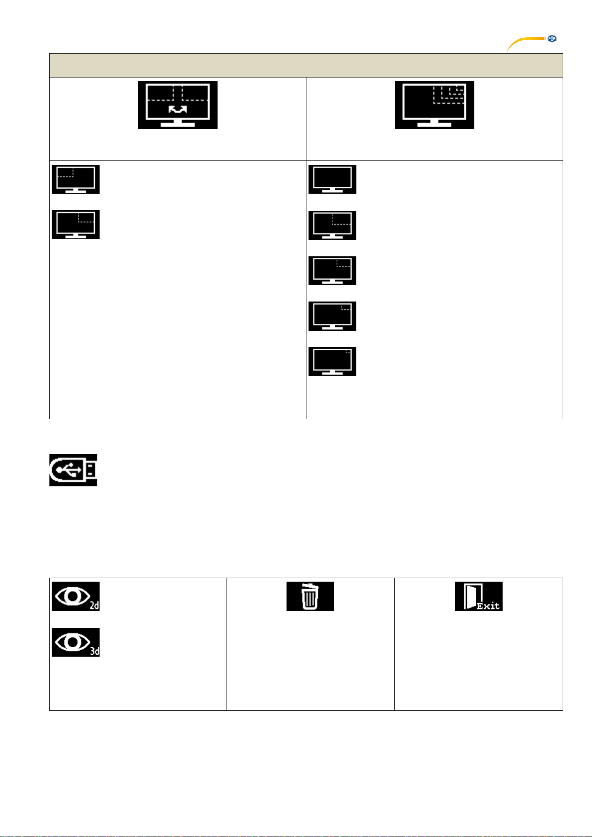
5.5.1 Split Screen
Via the split screen menu, you can have a static image permanently displayed on the monitor. You can choose
between loading an image from the USB stick or displaying a screen shot of the current live image of the camera.
The following symbol appears at the bottom of the screen when the split screen mode is activated:
Split Screen Menu Items
Load image from
USB stick
Load live image
Change split screen
settings
Turn split screen off
Leave menu
C
A
B
C
C

15
USB
Select this menu item to have an image from your USB stick displayed. After clicking on the symbol, a list of the files
on the stick opens. Selectable files are displayed white; non-selectable files are displayed gray. Please note that only
images in the *.bmp format can be displayed.
When you hold the bar over a file name for approx. 2 seconds, a preview of the image is displayed. After you select
a file, you have the following options:
Display the image in 2D.
Display the image in 3D
(only possible if the file
contains 3D image
information).
Note: 3D images can only be
displayed in full-screen mode.
Delete the image.
Leave the menu.
The selected file is displayed red in the list.
Live Image
Select this menu item to have a screen shot of the live image displayed.
Note: 3D images can only be displayed in full-screen mode. Therefore, a screen shot of the live image can only be
displayed in 2D in the split screen. However, you can save screenshots of 3D images via the foot switch. See
chapter 5.6.
Split Screen Settings
Here you can select how the split screen image is displayed. You can adjust the position of the window (top left or
top right of the monitor) as well as its size.
16
Menu Items Split Screen Settings
Position
Size
The split screen image is displayed in the
top left of the monitor.
The split screen image is displayed in the
top right of the monitor.
The split screen image is displaed in full-
screen mode. (1/1)
The split screen image takes up half the
length and width of the screen. (1/2)
The split screen image takes up 3/8 of the
length and width of the screen. (3/8)
The split screen image takes up 1/4 of the
length and width of the screen. (1/4)
The split screen image takes up 1/8 of the
length and width of the screen. (1/8)
Note: 3D images can only be displayed in full-screen
mode.
5.5.2 USB
Note: This sub-menu has the same functions as the sub-menu “USB” in the split screen menu.
Select this menu item to have an image from your USB stick displayed. After clicking on the symbol, a list showing
the files on the stick opens. Selectable files are displayed white; non-selectable files are displayed gray. Please note
that only images in the *.bmp format can be displayed.
When you hold the bar over a file name for approx. 2 seconds, a preview of the image is displayed. After you select
a file, you have the following options:
Display the image in 2D.
Display the image in 3D
(only possible if the file
contains 3D image
information).
Note: 3D images can only be
displayed in full-screen mode.
Delete the image.
Leave the menu.
The selected file is displayed red in the list.
17
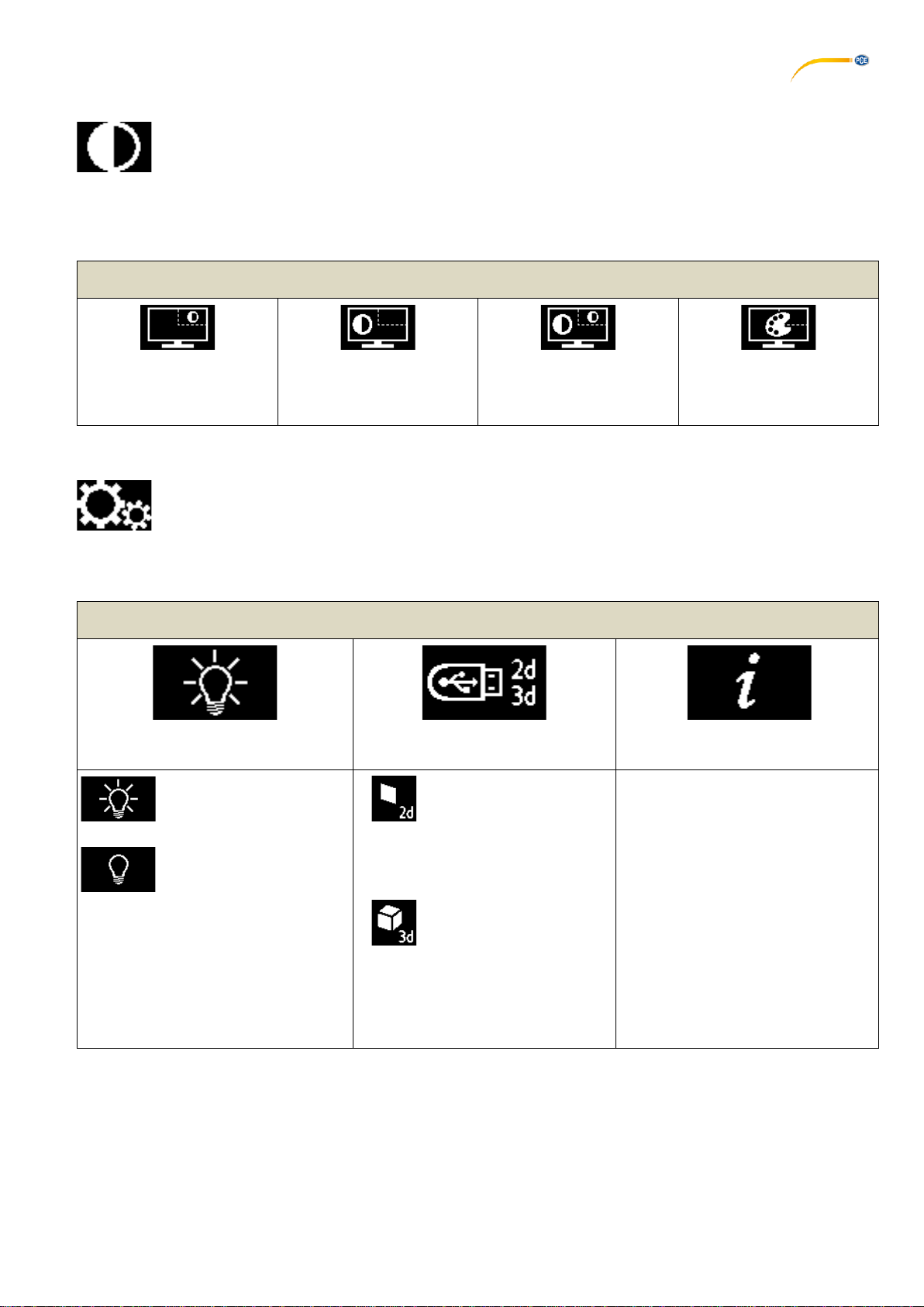
5.5.3 Black/White
In this menu, you can choose whether the live image and/or the split screen image are displayed in color or black
and white.
Black/White Menu Items
Live image in color
Split screen image black
and white
Live image black and white
Split screen image in color
Live image black and white
Split screen image black
and white
Live image in color
Split screen image in color
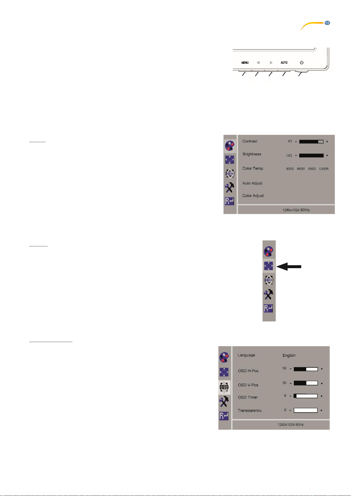
5.5.4 Settings
In the general settings, you can switch the lighting on and off, switch between 2D and 3D image saving mode and
query information about PCE-OVM 3D.
Settings Menu Items
Lighting
Saving in 2D/3D
Information
The lighting is switched
on.
The lighting is switched
off.
Screen shots are always
saved in 2D,
independently from the
general image
display
mode.
Screen shots are saved in
3D if the 3D image display
mode is enabled.
Note: 3D images can only be
displayed in full-screen mode. Saving
a 3D image takes twice as long as
saving a 2D image.
You can query the following
information here:
•Firmware type (2D or 3D)
•Firmware version
•Operating time
•IP address (when used
in a network)
•Host name (when used
in a network)

18
5.6 Screen Shot / Still Image
Using the foot switch, the monitor image can be frozen (still image) or also stored on the USB memory stick (screen
shot).
5.6.1 Still Image
⇒Press the foot switch for more than 1 sec.
The still image is displayed, meaning the monitor image is frozen.
While the still image is displayed, the following actions can be performed:
⇒Briefly press the foot switch.
The screen contents are saved to the USB stick as a screen shot.
⇒Press the foot switch for more than 1 sec.
Switch back to the live image.
The following settings can be changed while the still image is displayed:
•Switch between 2D and 3D display
•Switch magnification between 15x, 20x, 25x, and 30x.
When a still image is displayed on the screen, it is indicated by the following snowflake symbol:
5.6.2 Saving a Screen Shot
⇒Briefly press the foot switch.
The screen contents are saved to the USB stick as a screen shot.
The screen shot icon appears on the monitor.
The file name is displayed on the monitor during the save operation.
No other actions are possible during the save operation (approx. 5 sec in 2D; approx. 10 sec in 3D)
The file name has the following format:
•IMGxxx.bmp
•with xxx = sequential counter 000 to 999
If the USB memory stick is then connected to a PC, the file names can be changed as usual, e.g. to assign them to a
customer.
5.7 Working with 3D
After switching to the 3D display, a 3D image is generated on the monitor.
When working in 3D, the 3D glasses must be worn.
Looking at the 3D image without 3D glasses (for example, over the shoulder of another person) is very strenuous
and not recommended.
When working in 3D mode, it is important that the monitor is aligned correctly.
The monitor should be perpendicular to the viewing direction. Refer to Chapter 4.3.3.

19
6Monitor
PCE Instruments recommends not changing the factory settings of the monitor as the basic settings for PCE-OVM
3D.
6.1 Safety Instructions
Commissioning
►Do not close off the ventilation openings.
►Place the monitor in a well-ventilated place to avoid overheating.
►Only use accessories specified by the manufacturer or included with the monitor.
►Select a location where the monitor will not be exposed to extreme temperatures, high humidity, direct
sunlight, or dusty environments. Avoid proximity to equipment that generates strong magnetic fields.
Water and moisture
►Do not operate the monitor near water. To reduce the risk of fire and electric shock, do not expose the
monitor to rain or moisture.
Power cord and power cord connection
►Install the power cord so that it will not be walked on or damaged. Note the location of the cables, plugs,
sockets, and of the connector at the monitor.
Product care
►Do not touch the screen directly with your fingers. Grease from the skin may leave fingerprints on the
screen, which are difficult to remove and can damage the screen. Do not put any pressure on the screen.
Cleaning
►Clean only with a dry cloth.
Repair
►Do not repair the monitor yourself. High voltages are exposed when the cover is opened or removed.
There is danger of electrical shock. Repairs must be carried out by qualified personnel only.
Lightning strike
►For extra safety during a thunderstorm, or when the monitor is left unattended or unused for a long time,
unplug the power cord of the power supply and the monitor cable. This prevents damage to the monitor due
to lightning strikes and power surges.
Mains connection
►Do not remove the ground or the protective conductor connection from the mains plug of the power
supply unit.
►Unplug the power supply unit when the monitor is not used for an extended period of time, or if the power
cord, power plug, or monitor housing is damaged.
Caution
►Do not try to open the product. Any attempt to open the product or remove the cover will void the
warranty and may result in serious injury.
6.2 Connections
40 DC 12 V 3.33 A
41 DVI input
42 VGA input
Fig. 17
40
41
42
20
6.3 Operation and Settings
8Power switch
43 MENU, opens the monitor menu.
44 Signal source selection. Reduce the selected value in the monitor
menu.
45 Adjust brightness. Increase the selected value in the monitor menu.
46 AUTO, automatic horizontal and vertical adjustment of the image. It also exits the monitor
menu.
6.4 Monitor Menu
Color
Contrast
Adjust screen contrast (difference between light and dark regions of the
image).
Brightness
Adjust the image brightness.
Color Temp
Select between different, preset color temperatures or set your own
custom parameters (9300/6500/5500/USER).
Auto Adjust (not selectable). Fig. 19
Color Adjust (not selectable).
Image
The settings under this menu item are fixed and cannot be changed.
The menu item cannot be selected.
Fig. 20
Monitor Menu
Language
Select the language for the monitor menu (English, French / German /
Italian / Russian / Spanish / Portuguese / Japanese / Korean /
Traditional Chinese / Simplified Chinese).
Horizontal position of the monitor menu (QSD H-Pos.)
Adjust the horizontal position of the monitor menu (left or right).
Vertical position of the monitor menu (QSD V-Pos.)
Adjust the vertical position of the monitor menu (up or down).
Monitor menu time setting (QSD Timer)
Set the time that the monitor menu is displayed (3 - 60 seconds).
Transparency
Adjust the transparency of the monitor menu. Fig. 21
8
46
45
44
43
Fig. 18
Table of contents
Other PCE Health and Fitness Microscope manuals


