PCS Piezotronics Larson Davis AEC206 User manual

AEC206
Binaural Test Fixture

Larson Davis
AEC206 Binaural
Test Fixture
Reference Manual

AEC206 Reference Manual i-2
Copyright
Copyright 2017, by PCB Piezotronics, Inc. This manual is copyrighted, with all rights reserved. The manual may not be copied in
whole or in part for any use without prior written consent of PCB Piezotronics, Inc.
Disclaimer
The following paragraph does not apply in any state or country where such statements are not agreeable with local law:
Even though PCB Piezotronics, Inc. has reviewed its documentation, PCB Piezotronics Inc. makes no warranty or representation,
either expressed or implied, with respect to this instrument and documentation, its quality, performance, merchantability, or fit-
ness for a particular purpose. This documentation is subject to change without notice, and should not be construed as a commit-
ment or representation by PCB Piezotronics, Inc.
This publication may contain inaccuracies or typographical errors. PCB Piezotronics, Inc. will periodically update the material for
inclusion in new editions. Changes and improvements to the information described in this manual may be made at any time.
Record of Serial Number and Purchase Date
AEC206 Serial Number: ___________
426M11 Serial Number: ___________ Serial Number: ___________
AEC304 Serial Number: ___________ Serial Number: ___________
Recycling
PCB Piezotronics, Inc. is an environmentally friendly organization and encourages our customers to be environmentally conscious.
When this product reaches its end of life, please recycle the product through a local recycling center or return the product to:
PCB Piezotronics, Inc.
Attn: Recycling Coordinator
1681 West 820 North
Provo, Utah, USA 84601-1341
where it will be accepted for disposal
Warranty
For warranty information, refer to our Terms and Conditions of Sale on our website, www.larsondavis.com/TermsConditions.aspx.
i.1 Contact Larson Davis
Website
www.larsondavis.com
Worldwide Corporate Headquarters
Larson Davis - a PCB Piezotronics division
3425 Walden Avenue
Depew, NY 14043-2495 USA
Toll-free (in the US): 888-258-3222
Phone: 716-926-8243
USA fax: 716-926-8215
E-mail: [email protected]om

AEC206 Reference Manual ii-1
Table of Contents
Module 1 Getting Started 1-1
1.1 Overview ...............................................................................................................................................................1-1
1.2 Components ........................................................................................................................................................1-2
1.3 Connecting to Analyzer .....................................................................................................................................1-4
1.4 Performing Calibration ......................................................................................................................................1-6
Module 2 Assembly 2-1
2.1 Overview ...............................................................................................................................................................2-1
2.2 Mounting Artificial Pinnae .................................................................................................................................2-2
2.3 Ear Simulator and Preamplifier .......................................................................................................................2-3
2.4 Storage ............................................................................................................................................................... 2-12
Appendix A Technical Specifications A-1
A.1 AEC206 ................................................................................................................................................................. A-1
A.2 426M11 Microphone Preamplifier .................................................................................................................. A-2
A.3 Isolation Testing ................................................................................................................................................ A-2
A.4 Transfer Functions ............................................................................................................................................. A-3
A.5 Declaration of Conformity ............................................................................................................................... A-9

AEC206 Reference Manual Overview 1-1
Module 1Getting Started
1.1 Overview ................................................................................................................................................ 1-1
1.2 Components ......................................................................................................................................... 1-2
1.2.1 Optional Accessories .......................................................................................................... 1-3
1.3 Connecting to Analyzer ....................................................................................................................... 1-4
1.4 Performing Calibration ....................................................................................................................... 1-6
1.1 Overview
The AEC206 is a binaural test fixture used for testing headphones and
earbuds, both supra-aural and circum-aural as well as hearing protection
devices.
In the head of the fixture are two 426M11 preamplifiers with AEC304
occluded ear simulators. It is stabilized and mounted on a steel circular
base. Included are two sets of pinnae with two hardness grades.
AEC206 complies with applicable portions of the International Standards
ISO 4869-3 and IEC 60318-4.
FIGURE 1-1 AEC206 Anatomy
Neck Cavity
(located in back)
Base
Alignment
Screw
Head
Neck
Face
Hat
Alignment
Ring
Preamplifier
Cables

AEC206 Reference Manual Components 1-2
1.2 Components
The test fixture needs to be removed with care. For this purpose, a sling is
provided. With one hand pull the sling upwards, and ease the base of the
test fixture out of the case with your other hand. To carry the AEC206, hold
both the neck and head simultaneously.
FIGURE 1-2 AEC206 Components
LEFT
AEC304 IEC
60318-4
Occluded Ear
Simulator
RIGHT
AEC304 IEC
60318-4
Occluded Ear
Simulator
AEC206-RING
Alignment Ring
with screws
SAE206.01 AEC206
Binaural Test
Fixture with nylon
sling
ADP105 adapter
for a CAL250
calibrator
Pinnae
AEC-L0035 Left
Pinna Shore OO-35
AEC-R0035 Right
Pinna Shore OO-35
AEC-LA25 Left Pinna
Shore A-25
AEC-RA25 Right
Pinna Shore A-25
LEFT 426M11 short 1/2” Preamplifiers with
integrated cable & BNC connector
TAKE NOTE Each AEC304 and 426M11 are a mated pair. They cannot be
interchanged, see 2.3.1 "Mated Pair" on page 2-3.
RIGHT 426M11 short 1/2” Preamplifiers
with integrated cable & BNC connector
CCS050 hard case
with custom foam

AEC206 Reference Manual Components 1-3
FIGURE 1-3 Tools
1.2.1 Optional Accessories
CAL250
Battery operated precision microphone calibrator used for the calibration
of the AEC304 and other Larson Davis sound measurement equipment. It
has a full 114.0 dB level output signal at 251.2 Hz.
AEC206-CUP
Isolation test copper cup with foam insert used for isolation testing to
confirm compliance with ISO 4869-3. Requires two cups.
Silicon Grease 2.5 mm Hex Driver
For neck, vent, and
set screws
2 mm Hex Driver
For alignment
ring screws
1.5 mm Hex Driver
For alignment screw

AEC206 Reference Manual Connecting to Analyzer 1-4
1.3 Connecting to Analyzer
A basic headphone test can be made with the following mechanical
setup:
FIGURE 1-4 Basic Headphone Configuration

AEC206 Reference Manual Connecting to Analyzer 1-5
FIGURE 1-5 Headphone Test with Impedance/T-S

AEC206 Reference Manual Performing Calibration 1-6
1.4 Performing Calibration
There are several ways the system is calibrated:
TEDS
The AEC304 is equipped with TEDS sensors. TEDS (Transducer Electronic
Data Sheet) sensors allow TEDS enabled analyzers to automatically read
sensitivity data from the sensor.
Factory Calibration
Periodically the AEC206 is shipped to Larson Davis for factory calibration.
An alternative method for factory calibration is to remove the AEC304 and
paired 426M11 and ship to Larson Davis, then reassemble when returned.
This alternate method calibrates the AEC304 and 426M11 only, it does not
verify that the unit complies with isolation test as described in ISO 4869-3.
For information on removal, see 2.3.2 "Removing Ear Simulator and
Preamplifier" on page 2-4.
Acoustic Calibration
A technician performs a manual acoustic calibration at the beginning and
end of the day (or test) to ensure the test was performed accurately.
The following procedures describe an acoustic calibration:
Step 1 Ensure the ADP105 adaptor is securely on the CAL250.
TAKE NOTE Unless you use the
CAL250 on another device,
there is no need to remove the
adapter between use.
Step 2 If pinna and ring are installed, remove prior to calibration.
See “Removing Artificial Pinna” on page 2-3.
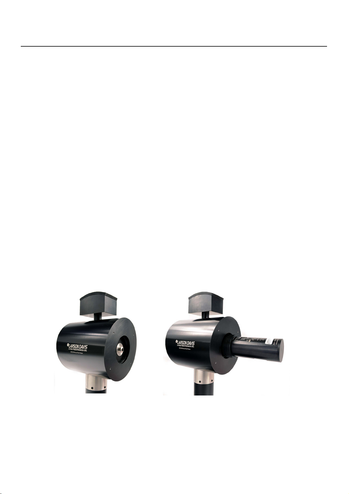
Step 3 Place calibrator over the microphone. Gently secure the
gasket-tight connection with a push.
FIGURE 1-6 Calibration Setup
Step 4 Turn calibrator on by pressing the button.
TAKE NOTE The CAL250 will run
for 60 seconds after you turn it
on.
Step 5 Run the calibration process on the connected analyzer.
Step 6 When the calibration is complete, position your hand on the
bottom half of the calibrator, and then bend it up or down
about ten degrees, then pull outward. Do not pull outward

AEC206 Reference Manual Performing Calibration 1-7
until the connection is loose, otherwise you may break the
ADP105 or pull the AEC304 out of the head.
FIGURE 1-7 Remove Calibrator
Step 7 Repeat calibration on the opposite side.

AEC206 Reference Manual Overview 2-1
Module 2Assembly
2.1 Overview ................................................................................................................................................ 2-1
2.1.1 Left and Right Identification .............................................................................................. 2-1
2.2 Mounting Artificial Pinnae .................................................................................................................. 2-2
2.2.1 Removing Artificial Pinna ................................................................................................... 2-3
2.3 Ear Simulator and Preamplifier ........................................................................................................ 2-3
2.3.1 Mated Pair ............................................................................................................................. 2-3
2.3.2 Removing Ear Simulator and Preamplifier ..................................................................... 2-4
2.3.3 Assembling AEC304 ............................................................................................................. 2-7
2.4 Storage .................................................................................................................................................2-12
2.1 Overview
Assembly and disassembly should only be done after reading all the
procedures. Additionally you can find assembly instruction videos online,
see https://www.youtube.com/user/LarsonDavisPCB
2.1.1 Left and Right Identification
TAKE NOTE The preamplifier
cables are marked with blue or
red to identify which is left and
right.
The AEC206 is binaural, meaning it is a two ear system. The “face” of the
device is the side of the head with the logo, and the left and right sides are
in reference to that “face”. The figure below has been colored to represent
left (blue) and right (red).
FIGURE 2-1 Left and Right
RIGHT SIDE LEFT SIDE
The “L” in the product
name of the pinna
indicates left
The “R” in the product
name of the pinna
indicates right

AEC206 Reference Manual Mounting Artificial Pinnae 2-2
2.2 Mounting Artificial Pinnae
The AEC206 has two pinna options:
• Artificial Pinna shore OO-35; left and right
• Primary use
• Artificial Pinna shore A-25; left and right
• Alternative option, for example, free field checks
TAKE NOTE The pinna can be
installed before or after the
ring has been installed. If the
ring is already mounted, ease
the pinna into the space with
your finger until the edges are
flush under the plate.
To mount the artificial pinnae, follow these steps:
Step 1 Align the bottom notch on the back of the pinna with the
alignment screw on the AEC206, push into place.
Step 2 Mount the alignment ring using the supplied 2 mm hex
driver and the four 2.5 mm screws. Gently turn the screws
and stop once they are secure. Do not over tighten.
TRY THIS If you lift up the
earlobe, the notch in the pinna
and the notch in alignment
ring will make a small circle.
This indicates that you have
mounted them correctly.
FIGURE 2-2 Pinna Assembly

AEC206 Reference Manual Ear Simulator and Preamplifier 2-3
2.2.1 Removing Artificial Pinna
Follow these steps to remove the pinna:
Step 1 Use the 2 mm hex driver to remove all four screws from the
ring.
Step 2 Remove the artificial pinna and the ring.
2.3 Ear Simulator and Preamplifier
2.3.1 Mated Pair
The preamplifiers and ear simulators cannot be interchanged. They are in
sets, or mated pairs. Each pair consists of one preamplifier and one
occluded ear simulator. Additionally, a left pair can only be used for the
left ear testing and the right pair can only be used for right ear testing. See
“Left and Right Identification” on page 2-1.
The AEC304 and 426M11 are mated to ensure correct calibration data
from TEDS. If devices are mixed then the calibration data provided by
TEDS will be incorrect.
Refer to the labels and certifications to know which items are paired
based on the serial numbers.
FIGURE 2-3 Paired Serial Numbers
AEC304 S/N 0139
For use with
426M11 S/N 495
426M11 S/N 495
For use with
AEC304 S/N 0139
Match
Match

AEC206 Reference Manual Ear Simulator and Preamplifier 2-4
2.3.2 Removing Ear Simulator and Preamplifier
The AEC304 will already be assembled in the head of the AEC206 test
fixture. Larson Davis recommends that the entire system be shipped for
factory calibration, however, the following procedures describe removing
the ear simulator and preamplifier to ship to Larson Davis separately. It is
important to reassemble using the steps below exactly in order to
maintain acoustic quality, see 2.3.3 "Assembling AEC304" on page 2-7.
To remove the AEC304 follow these steps:
Step 1 Disconnect the preamplifier cable from the analyzer.
Step 2 Using the supplied 2.5 mm hex driver, remove the set screws
on the head by turning the recessed set screw
counterclockwise. Ensure you store the screws as they are
imperative to the acoustical quality of the device.
FIGURE 2-4 Remove head set screws
Step 3 To release the vacuum like seal inside the head, allowing for
easy removal of the head, you can loosen one AEC304 and
set it out slightly, though this is not necessary. DO NOT pull
cable slack; only remove <1 inch of cable.
Alternatively, to assist in removal, you can attach the
calibrator and pull horizontally. Extreme force is not
necessary and may result in damaging the equipment.
Step 4 Using the supplied 2.5 mm hex driver, release the clamp on
the neck by turning the neck screws counterclockwise until
two or three threads are visible.
FIGURE 2-5 Loosen neck set screws
Use the hex
driver to
remove set
screws
Neck
screw
locations

AEC206 Reference Manual Ear Simulator and Preamplifier 2-5
Step 5 Hold the base down with one hand and pull from the hat to
separate the head and the neck. There is a vacuum seal to
the head and the neck, additional force may need to be
applied to the base, however avoid twisting, this may cause
the cables to break. Set head next to the stand with the
cables loose.
FIGURE 2-6 Remove head and neck
Step 6 Gently pull the wires from the gasket by pulling away from
the stand. If they don’t come loose easily, use a hex driver to
remove the washer and gasket, then gently pull the cables
out of the gasket.
FIGURE 2-7 Gently remove cable from stand

AEC206 Reference Manual Ear Simulator and Preamplifier 2-6
Step 7 Gently pull the AEC304 completely out of the head. Feed the
cable up through the head and out the side.
FIGURE 2-8 Remove AEC304
Step 8 Separate the 426M11 from the AEC304 by unscrewing the
two devices. Do not unscrew the ear canal extension.
FIGURE 2-9 Separate Preamplifier and Ear Simulator
Separate here
Do Not remove ear
canal extension

AEC206 Reference Manual Ear Simulator and Preamplifier 2-7
2.3.3 Assembling AEC304
Ensure the correct AEC304 and mated 426M11 are to be installed on the
correct side. To learn more see 2.1.1 "Left and Right Identification" on
page 2-1.
FIGURE 2-10 Left and Right
TAKE NOTE It is important to
follow these steps exactly to
ensure the quality of the
acoustic testing.
To install AEC304 follow these steps:
Step 1 Connect AEC304 to 426M11 preamplifier by pushing together
and screwing hand-tight.
Step 2 Insert assembly into the cavity of the head, feeding the cable
down through the bottom. Push until set.
FIGURE 2-11 Insert AEC304
Back of head
Right Side
(red)
Left Side
(blue)

AEC206 Reference Manual Ear Simulator and Preamplifier 2-8
Step 3 Using the 2.5 mm hex driver, unscrew the washer/gasket
screw completely. Pull off assembly, and then separate the
washer from the gasket.
FIGURE 2-12 Remove Gasket
Step 4 Place head next to stand. See Figure 2-13.
Step 5 Measure approximately six inches of cable starting from the
neck insert and running down, and at that spot gently push
the cables into the gasket as shown below. The length of
cable between the gasket and neck insert should be ~6 in.
FIGURE 2-13 Insert cables into gasket

AEC206 Reference Manual Ear Simulator and Preamplifier 2-9
TAKE NOTE Align the gasket slit
with the center of the cavity in
the neck, so the cables run
down into the neck.
Step 6 Place gasket on the neck with cables running down into the
cavity. Place washer on top and screw together with a torque
of 20 oz-in to provide an optimal seal.
Step 7 While turning the screw, squeeze the slit of the gasket
together. After you let go, the slit should be fully closed.
FIGURE 2-14 Secure gasket
Step 8 Liberally grease the edges of the gasket.
FIGURE 2-15 Grease gasket
Step 9 Feed the slack of the cables into the head. Ensure all cables
are all the way in before moving on to the next step, if the
Squeeze the
slit in the
gasket shut as
you tighten the
screw.
Table of contents
Popular Test Equipment manuals by other brands

Hioki
Hioki IM9201 instruction manual

Nagas
Nagas ABE Series Installation, operation and maintenance manual

Tektronix
Tektronix 2216 user manual

Larsen & Toubro
Larsen & Toubro Universal Test Kit instruction manual

Rothenberger
Rothenberger ROTEST Electronic 3 Instructions for use

EXFO
EXFO Power Blazer Quick reference guide