B&K 606 User manual
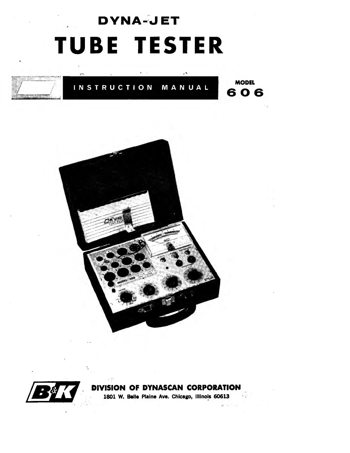
DYNA-JET
TUBE TESTER
INSTRUCTION MANUAL MODEL
606
DIVISION OF DYNASCAN CORPORATION
1801 W. Ml* Plain* Ave. Chicago, Illinois 60613
OPERATING INSTRUCTIONS
FOR
Model 606
DYNA-JET
TUBE TESTER
B&KDIVISION OF DYNASCAN CORP.
1801 West Belle Plaine Avenue
Chicago, Illinois 60613
MODEL 606 TUBE TESTER
What It Will Do
1. The Dyna Jet Model 606 Tube Tester will test all of the commonly
used tubes in general use in radio and television sets.
2. In addition it will test many voltage regulator tubes, thyratron tubes,
industrial types of tubes and many of the European types found in
modem hi fi equipment.
3. Each tube is automatically checked for shorts and leakage to approxi-
mately one megohm. These tests are made from each element to every
other element so that all possible combinations of shorts can be detected.
4. Grid Emission, Gas, Grid Contamination, or obscure Grid to Cathode
leakage are all disclosed by an exceptionally sensitive grid current
check. This test will reveal as little as 2to 3microamperes of current
in the grid circuit and can be adjusted for asensitivity of over
100 megohms.
5. Each section of amulti section tube is checked separately.
6. Each tube is checked for quality in atest circuit that determines the
full capability of cathode emission under current loads simulating
actual operating conditions.
Testing Tubes for Shorts
The Shorts check is automatically made when atube is placed in the
proper socket.
The Shorts check uses aneon lamp as the indicator. Shorts or leakages to
approximately 1megohm will cause this lamp to glow. This Shorts indicator
is located just below the meter. See Fig. 1.
Acheck on grid to cathode leakage is made as soon as the tube is plugged
into the socket. The Shorts check between all other elements is made by
rotating the switch “C” through its positions, observing the Shorts light as
the switch is rotated.
Testing Tubes for Quality
The test for the quality of a tube is acomprehensive cathode emission test.
It is important to test the tube under aload condition which will insure that a
tube passing this test will have adequate emission to properly operate in
acircuit.
3
TESTING TUBES FOR GRID EMISSION AND GAS
The Grid Emission and Gas Test is an invaluable aid in TV servicing be-
cause it quickly picks out those tubes which can cause trouble in a.g.c., sync,
I.F. amplifier, and R.F. tuner circuits.
In order to understand how atube can have “grid emission” and “gas cur-
rent” we must look into the theory of electron tubes.
There is normally some little evaporation of the cathode coating material
on the grid of atube. Some of this vapor tends to deposit on the grid and
gives rise to what is known as “grid emission”, where the grid itself emits
electrons and draws current commonly known as “negative grid current”.
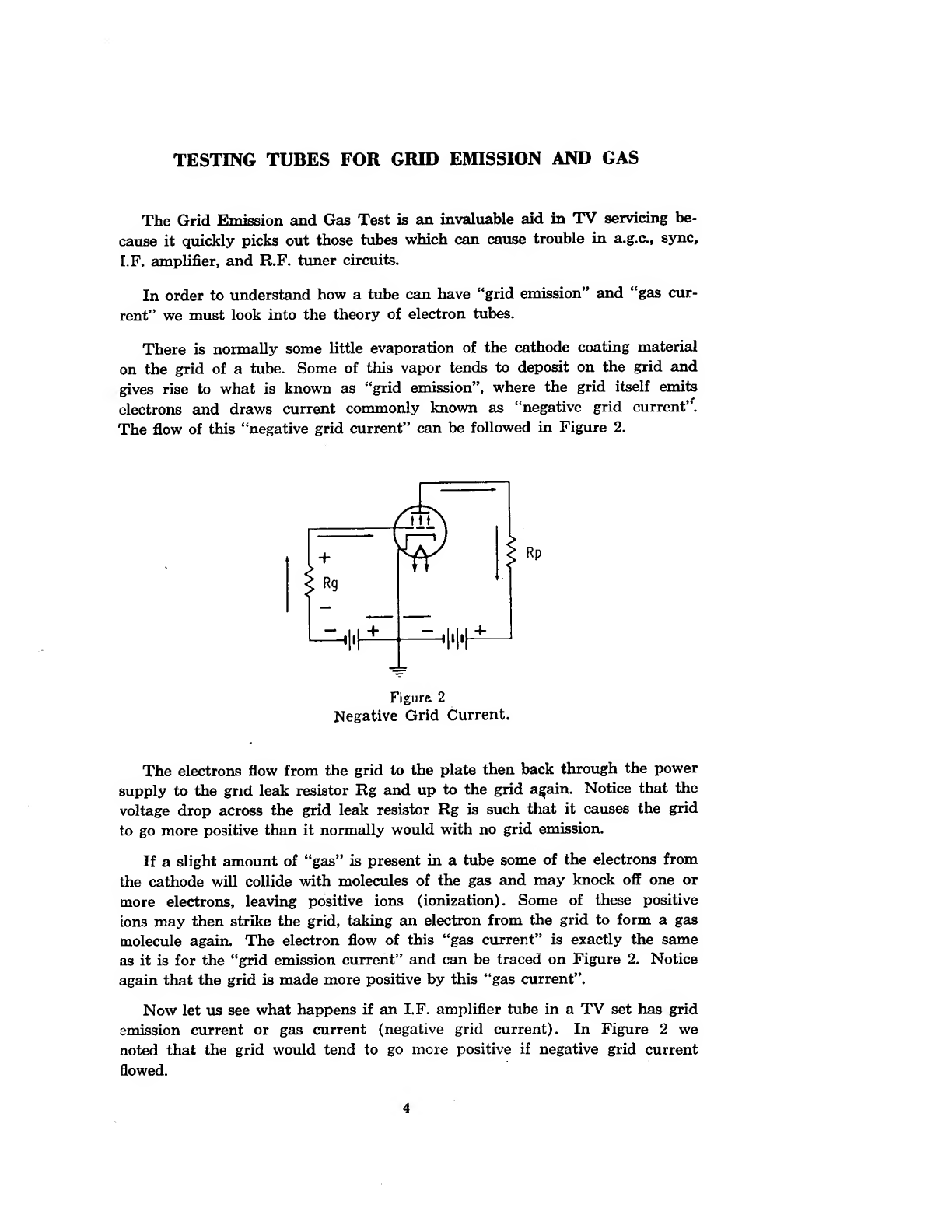
The flow of this “negative grid current” can be followed in Figure 2.
Negative Grid Current.
The electrons flow from the grid to the plate then back through the power
supply to the grid leak resistor Rg and up to the grid again. Notice that the
voltage drop across the grid leak resistor Rg is such that it causes the grid
to go more positive than it normally would with no grid emission.
If aslight amount of “gas” is present in atube some of the electrons from
the cathode will collide with molecules of the gas and may knock off one or
more electrons, leaving positive ions (ionization). Some of these positive
ions may then strike the grid, taking an electron from the grid to form agas
molecule again. The electron flow of this “gas current” is exactly the same
as it is for the “grid emission current” and can be traced on Figure 2. Notice
again that the grid is made more positive by this “gas current”.
Now let us see what happens if an I.F. amplifier tube in aTV set has grid
emission current or gas current (negative grid current). In Figure 2we
noted that the grid would tend to go more positive if negative grid current
flowed.
4
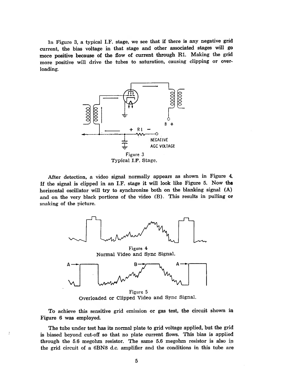
In Figure 3, atypical I.F. stage, we see that if there is any negative grid
current, the bias voltage in that stage and other associated stages will go
more positive because of the flow of current through HI. Making the grid
more positive will drive the tubes to saturation, causing clipping or over-
loading.
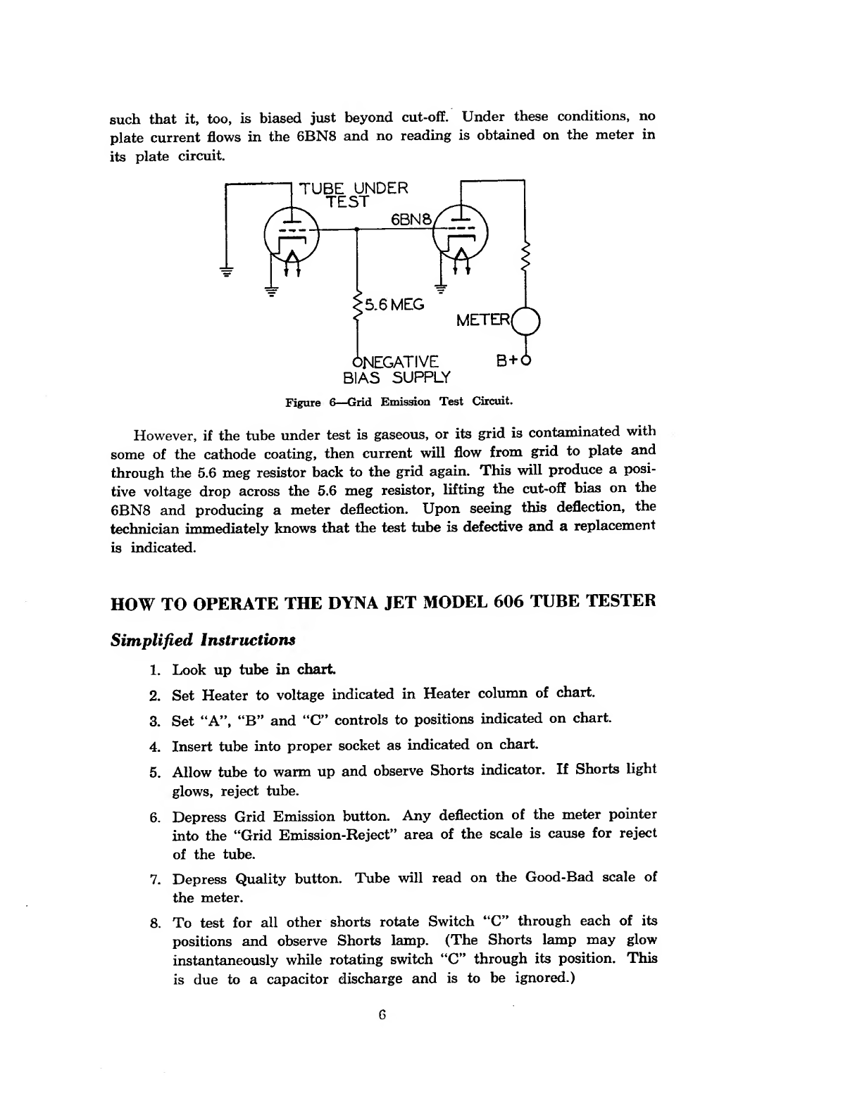
After detection, avideo signal normally appears as shown in Figure 4.
If the signal is clipped in an I.F. stage it will look like Figure 5. Now the
horizontal oscillator will try to synchronize both on the blanking signal (A)
and on the very black portions of the video (B). This results in pulling or
snaking of the picture.
A—
Figure 5
Overloaded or Clipped Video and Sync Signal.
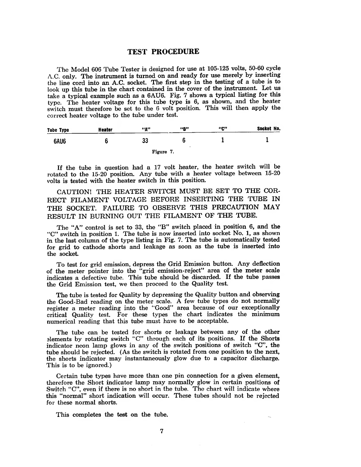
To achieve this sensitive grid emission or gas test, the circuit shown in
Figure 6was employed.
The tube under test has its normal plate to grid voltage applied, but the grid
is biased beyond cut-off so that no plate current flows. This bias is applied
through the 5.6 megohm resistor. The same 5.6 megohm resistor is also in
the grid circuit of a6BN8 d.c. amplifier and the conditions in this tube are
5
such that it, too, is biased just beyond cut-off. Under these conditions, no
plate current flows in the 6BN8 and no reading is obtained on the meter in
its plate circuit.
However, if the tube under test is gaseous, or its grid is contaminated with
some of the cathode coating, then current will flow from grid to plate and
through the 5.6 meg resistor back to the grid again. This will produce aposi-
tive voltage drop across the 5.6 meg resistor, lifting the cut-off bias on the
6BN8 and producing ameter deflection. Upon seeing this deflection, the
technician immediately knows that the test tube is defective and areplacement
is indicated.
HOW TO OPERATE THE DYNA JET MODEL 606 TUBE TESTER
Simplified Instructions
1. Look up tube in chart
2. Set Heater to voltage indicated in Heater column of chart.
3. Set ‘‘A”, “B” and “C” controls to positions indicated on chart.
4. Insert tube into proper socket as indicated on chart.
5. Allow tube to warm up and observe Shorts indicator. If Shorts light
glows, reject tube.
6. Depress Grid Emission button. Any deflection of the meter pointer
into the “Grid Emission-Reject” area of the scale is cause for reject
of the tube.
7. Depress Quality button. Tube will read on the Good-Bad scale of
the meter.
8. To test for all other shorts rotate Switch “C” through each of its
positions and observe Shorts lamp. (The Shorts lamp may glow
instantaneously while rotating switch “C” through its position. This
is due to acapacitor discharge and is to be ignored.)
6
TEST PROCEDURE
The Model 606 Tube Tester is designed for use at 105-125 volts, 50-60 cycle
A.C. only. The instrument is turned on and ready for use merely by inserting
the line cord into an A.C. socket. The first step in the testing of atube is to
look up this tube in the chart contained in the cover of the instrument. Let us
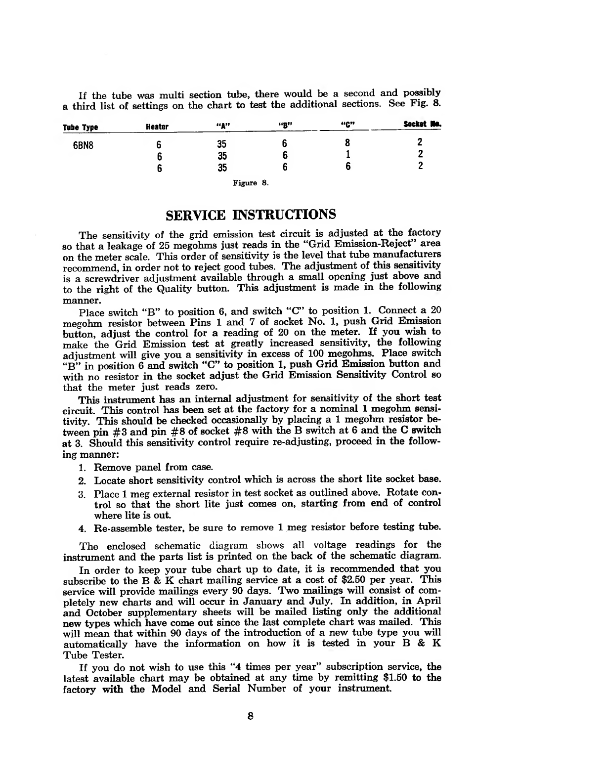
take atypical example such as a6AU6. Fig. 7shows atypical listing for this
type. The heater voltage for this tube type is 6, as shown, and the heater
switch must therefore be set to the 6volt position. This will then apply the
correct heater voltage to the tube under test.
Tube Type Heater "A” “C” Socket No.
6AU6 633 611
Figure 7.
If the tube in question had a17 volt heater, the heater switch will be
rotated to the 15-20 position. Any tube with aheater voltage between 15-20
volts is tested with the heater switch in this position.
CAUTION! THE HEATER SWITCH MUST BE SET TO THE COR-
RECT FILAMENT VOLTAGE BEFORE INSERTING THE TUBE IN
THE SOCKET. FAILURE TO OBSERVE THIS PRECAUTION MAY
RESULT IN BURNING OUT THE FILAMENT OF THE TUBE.
The “A” control is set to 33, the “B” switch placed in position 6, and the
“C” switch in position 1. The tube is now inserted into socket No. 1, as shown
in the last column of the type listing in Fig. 7. The tube is automatically tested
for grid to cathode shorts and leakage as soon as the tube is inserted into
the socket
To test for grid emission, depress the Grid Emission button. Any deflection
of the meter pointer into the “grid emission-reject” area of the meter scale
indicates adefective tube. This tube should be discarded. If the tube passes
the Grid Emission test, we then proceed to the Quality test.
The tube is tested for Quality by depressing the Quality button and observing
the Good-Bad reading on the meter scale. Afew tube types do not normally
register ameter reading into the “Good” area because of our exceptionally
critical Quality test. For these types the chart indicates the minimum
numerical reading that this tube must have to be acceptable.
The tube can be tested for shorts or leakage between any of the other
dements by rotating switch “C” through each of its positions. If the Shorts
indicator neon lamp glows in any of the switch positions of switch “C”, the
tube should be rejected. (As the switch is rotated from one position to the next,
the shorts indicator may instantaneously glow due to acapacitor discharge.
This is to be ignored.)
Certain tube types have more than one pin connection for agiven element,
therefore the Short indicator lamp may normally glow in certain positions of
Switch “C”, even if there is no short in the tube. The chart will indicate where
this “normal” short indication will occur. These tubes should not be rejected
for these normal shorts.
This completes the test on the tube.
7
If the tube was multi section tube, there would be asecond and possibly
athird list of settings on the chart to test the additional sections. See Fig- 8.
Tube Type Heater “A” “B" ilQtf socket He.
6BN8 635 682
635 612
635 662
Figure 8.
SERVICE INSTRUCTIONS
The sensitivity of the grid emission test circuit is adjusted at the factory
so that aleakage of 25 megohms just reads in the “Grid Emission-Reject” area
on the meter scale. This order of sensitivity is the level that tube manufacturers
recommend, in order not to reject good tubes. The adjustment of this sensitivity
is ascrewdriver adjustment available through asmall opening just above and
to the right of the Quality button. This adjustment is made in the following
manner.
Place switch “B” to position 6, and switch “C” to position 1. Connect a20
megohm resistor between Pins 1and 7of socket No. 1, push Grid Emission
button, adjust the control for areading of 20 on the meter. If you wish to
make the Grid Emission test at greatly increased sensitivity, the following
adjustment will give you asensitivity in excess of 100 megohms. Place switch
“B” in position 6and switch “C” to position 1, push Grid Emission button and
with no resistor in the socket adjust the Grid Emission Sensitivity Control so
that the meter just reads zero.
This instrument has an internal adjustment for sensitivity of the short test
circuit. This control has been set at the factory for anominal 1megohm sensi-
tivity. This should be checked occasionally by placing a1megohm resistor be-
tween pin #3 and pin #8 of socket #8 with the Bswitch at 6and the Cswitch
at 3. Should this sensitivity control require re-adjusting, proceed in the follow-
ing manner:
1. Remove panel from case.
2. Locate short sensitivity control which is across the short lite socket base.
3. Place 1meg external resistor in test socket as outlined above. Rotate con-
trol so that the short lite just comes on, starting from end of control
where lite is out.
4. Re-assemble tester, be sure to remove 1meg resistor before testing tube.
The enclosed schematic diagram shows all voltage readings for the
instrument and the parts list is printed on the back of the schematic diagram.
In order to keep your tube chart up to date, it is recommended that you
subscribe to the B&Kchart mailing service at acost of $2.50 per year. This
service will provide mailings every 90 days. Two mailings will consist of com-
pletely new charts and will occur in January and July. In addition, in April
and October supplementary sheets will be mailed listing only the additional
new types which have come out since the last complete chart was mailed. This
will mean that within 90 days of the introduction of anew tube type you will
automatically have the information on how it is tested in your B&K
Tube Tester.
If you do not wish to use this “4 times per year” subscription service, the
latest available chart may be obtained at any time by remitting $1.50 to the
factory with the Model and Serial Number of your instrument.
8

WARRANTY SERVICE INSTRUCTIONS
1. Refer to the maintenance section of the instruction manual for adjust-
ments that may be applicable.
2. Check common electronic parts such as tubes and batteries. Always
check instruction manual for applicable adjustments after such
replacement.
3. Defective parts removed from units which are within the warranty
period should be sent to the factory prepaid with model and serial
number of product from which removed and date of product purchase.
These parts will be exchanged at no charge.
4. If the above mentioned procedures do not correct the difficulty, pack
the product securely (preferably double packed). Adetailed list of
troubles encountered must be enclosed as well as your name and
address. Forward prepaid (express preferred) to the nearest B&K
authorized service agency.
Contact your local B&K Distributor for the name and location of your
nearest service agency, or write to
Service Department
B&K DIVISION OF DYNASCAN CORPORATION
1801 West Belle Plaine Avenue
Chicago, Illinois 60613
Other manuals for 606
1
Table of contents
Other B&K Test Equipment manuals


Popular Test Equipment manuals by other brands


Gossen MetraWatt
Gossen MetraWatt PROFITEST 2 DIN VDE 0100 operating instructions

Andatech
Andatech ALX3000 user manual

Bacharach
Bacharach INJECTOR CALIBRATOR CD3 Installation & operation instruction

Associated Research
Associated Research HYAMP III 3140 Operation and service manual

SmartSafe
SmartSafe iSmartEV OM210 user manual

COBHAM
COBHAM AXRF RF Subsystem Getting started


