WST BT200 User manual

WS Technologies Inc.
Beacon Tester
Operator’s Manual
BT200
Version 1.30

ii
Information contained in this manual is subject to change without notice.
Please consult the website at www.wst.ca for new Operator’s Manual
updates. Complying with all applicable copyright laws is the
responsibility of the user. Without limiting the rights under copyright, no
part of this document may be reproduced, stored in a retrieval system,
or transmitted in any form or by any means including but not limited to,
electronic, mechanical, photocopying, recording, or otherwise, or for any
purpose, without the written permission of WS Technologies Inc. (WST).
WST may have patents, patent applications, trademarks, copyrights, or
other intellectual property rights covering subject matter in this
document. Except as expressly provided in any written license
agreement from WST, the furnishing of this document does not give you
any license to these patents, trademarks, copyrights, or other intellectual
property.
The purchaser shall not in any event be entitled to, and WST shall not
be liable for indirect, special, incidental or consequential damages of
any nature including, without limitation, business interruption costs, loss
of profit or revenue, loss of data, promotional or manufacturing
expenses, overhead, injury to reputation or loss of customers, even if
WST has been advised of the possibility of such damages. In any event,
purchaser's recovery from WST for any claim shall not exceed
purchaser's purchase price for the product giving rise to such claim
irrespective of the nature of the claim, whether in contract, tort, warranty,
or otherwise. WST shall not be liable for and purchaser shall indemnify,
defend and hold WST, its agents, distributors, dealers, successors and
assigns harmless from any and all claims, damages or losses, including
injury or death, arising from or relating to the use or failure of the
products.
Copyright © 2017 WS Technologies Inc.
All rights reserved.
Printed in Canada
October 2017

iii
CONTENTS
INTRODUCTION..................................................................................... 1
SUMMARY OF MODELS AND OPTIONS.............................................. 1
UNPACKING ........................................................................................... 1
BEFORE YOU START ............................................................................ 2
Charging the Battery:........................................................................... 2
GETTING STARTED............................................................................... 2
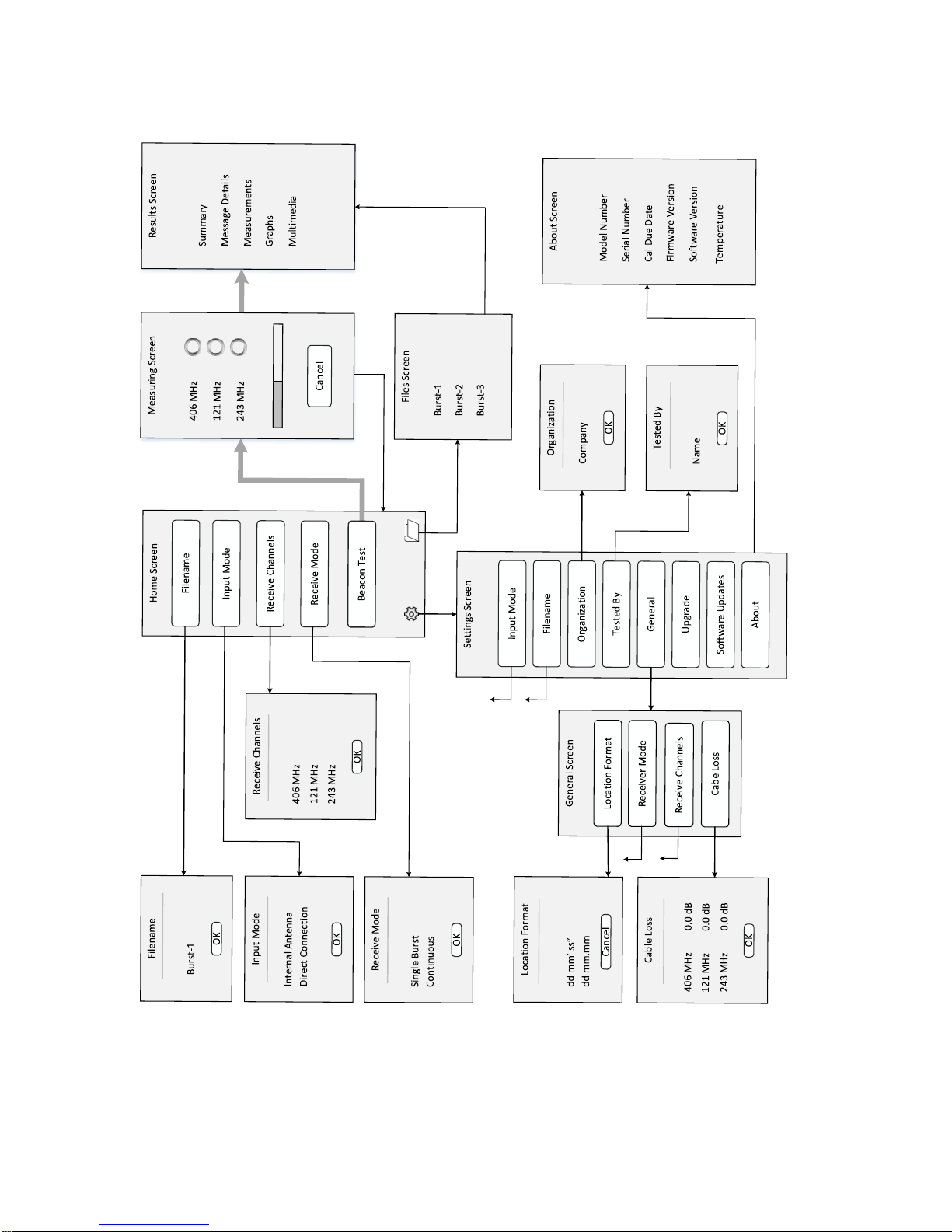
Flowchart:............................................................................................. 3
Running the Beacon Tester Application: ............................................. 4
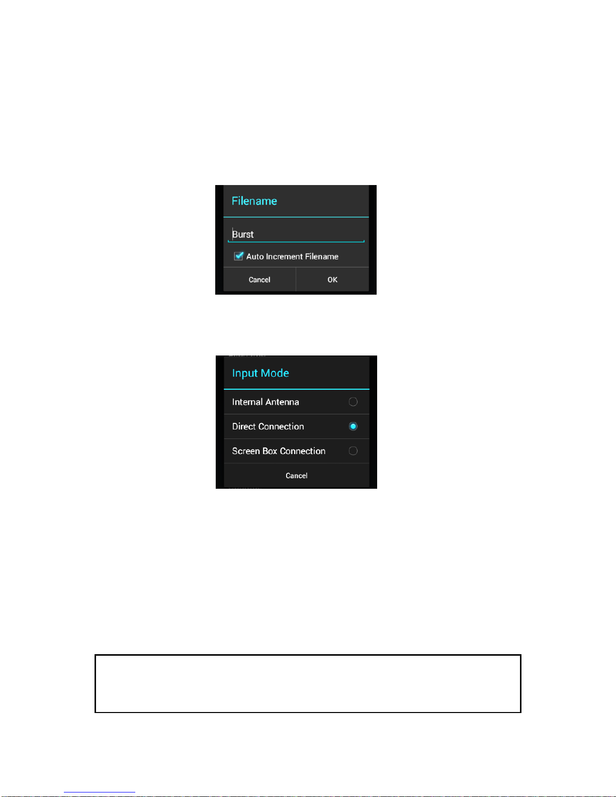
Selecting the Desired Measurement Filename:................................... 6
Selecting the Input Mode:.................................................................... 6
Selecting the Desired Receive Channels: ........................................... 7
Selecting the Desired Receive Mode:.................................................. 7
SETTING THE CONFIGURATION SETTINGS ...................................... 8
Setting the Organization and Tested By Names:................................. 8
General: ............................................................................................... 9
Location Coordinates Setting:.............................................................. 9
Selecting the Desired Receive Mode:................................................ 10
Selecting the Desired Receive Channels: ......................................... 10
Entering Cable Loss Factors:............................................................. 11
Upgrade: ............................................................................................ 11
Software Updates: ............................................................................. 11
Software Update Instructions:............................................................ 12
From the Google Play Store: ............................................................. 12
From the BT200 Handheld Device: ................................................... 13
From a PC:......................................................................................... 13
About:................................................................................................. 14
MAKING MEASUREMENTS................................................................. 15
General: ............................................................................................. 15
Connecting the Beacon:..................................................................... 16
Internal Antenna:................................................................................ 16
Direct Connection: ............................................................................. 16
Screen Box Connection:.................................................................... 16
Single Burst Measurement:................................................................ 17
Continuous Measurement:................................................................. 18
Viewing Measurements for Single Burst Mode:................................. 19
Viewing Measurements for Continuous Mode:.................................. 21
MEASUREMENT RESULTS................................................................. 22
Results Screen:.................................................................................. 22
Summary Section:.............................................................................. 22
Message Details: ............................................................................... 23
Measurements: .................................................................................. 23
Graphics:............................................................................................ 24

iv
Multi-Media Data:............................................................................... 25
Comments:......................................................................................... 25
Photos:............................................................................................... 25
Movies:............................................................................................... 25
Audio:................................................................................................. 25
FILES..................................................................................................... 26
Getting to the Files Screen: ............................................................... 26
Deleting Files: .................................................................................... 26
Deleting Files Using the PC:.............................................................. 27
TEST REPORTS AND DATA FILES..................................................... 28
Moving Measurement Folders: .......................................................... 28
Move to USB Drive (via OTG/USB Cable):........................................ 28
Move to PC: ....................................................................................... 29
Measurement Files: ........................................................................... 29
PDF Test Report:............................................................................... 29
Measurement Data File:..................................................................... 30
Graphics Files:................................................................................... 30
Multimedia Files:................................................................................ 30
SOFTWARE UPDATES........................................................................ 31
BEACON TESTER MODEL UPGRADING ........................................... 31
USING THE TSE100 SCREEN BOX .................................................... 31
FREQUENTLY ASKED QUESTIONS................................................... 32
SPECIFICATIONS................................................................................. 34
REGULATORY INFORMATION............................................................ 36
DECLARATION OF CONFORMITY...................................................... 37
WARRANTY INFORMATION................................................................ 38
CALIBRATION....................................................................................... 38
RETURNS ............................................................................................. 38
POWER CONVERSION CHART - dBm to Watts ................................. 39
WARNING!
WHEN USING DIRECT CONNECTION INPUT MODE DO NOT EXCEED A
BURST POWER LEVEL OF 20 WATTS OR A CONTINUOUS POWER
LEVEL OF 2 WATTS. DAMAGE WILL RESULT!
WARNING!
DO NOT ACTIVATE ANY BEACON IN ITS NORMAL ACTIVATE MODE
UNLESS THE BEACON IS IN A SCREEN BOX (TSE100) OR A SCREEN
ROOM. DOING SO COULD RESULT IN A FALSE DISTRESS ALERT.

1
INTRODUCTION
Thank you for choosing the BT200 series of 406 Beacon Testers.
This Operator’s Manual explains the operation of all available models:
BT200 and BT200 with ELT.
SUMMARY OF MODELS AND OPTIONS
BT200:This model measures and decodes all Cospas-Sarsat EPIRBs
and PLBs. It decodes the 406 MHz message, measures the 406 MHz
transmitter and the 121.5 MHz transmitter.
BT200 + ELT: This model measures and decodes all Cospas-Sarsat
EPIRBs, PLBs and ELTs. It decodes the 406 MHz message, measures
the 406 MHz transmitter, the 121.5 MHz transmitter, and the 243 MHz
transmitter.
High Stability Option: This option increases the frequency
measurement accuracies and allows for a 2 year calibration cycle,
compared to the standard 1 year calibration cycle.
UNPACKING
Please verify the contents of your package. It should contain:
●Rugged Smartphone with integrated Beacon Receiver
●Operator’s Manual
●Certificate of Calibration with Calibration data
●RF Interface cable
●USB interface cable
●AC Adapter with International Plug kit
●OTG/USB cable (for connecting a USB drive)
●Screen cleaning cloth
●Pen with stylus
●Waterproof yellow hard case

2
BEFORE YOU START
Charging the Battery:
Charge the BT200 using the AC adapter and USB cable for 4 hours.
TIP: To ensure a full charge, when the device power is low, always
charge the device for a minimum of 2 hours, regardless of the power
level showing on the device.
TIP: If the device has been off for a while, the battery may be in deep
discharge. Plug in the charger and leave for 10 hours. The device will
recover and the battery will charge fully.
GETTING STARTED
Please read this Operator’s Manual to become familiar with the
operation of the Beacon Tester.
POWER
button
RESET button
RF
INPUT
BACK button
USB port
VOLUME
UP
button
VOLUME
DOWN
button

3
Flowchart:
Screen Box Connection
dd.dddd°

4
Running the Beacon Tester Application:
Turn on the device by pressing and holding the Power button on the left
side for 5 seconds then releasing. The device will boot up.
Unlock the screen by sliding the lock icon.
Power Button

5
Launch the Beacon Tester application by tapping the Beacon Tester
icon on the device:
The 406 Beacon Tester title screen will show for a few seconds
followed by the Home screen:
BEACON
TEST button
Beacon Tester icon
SETTINGS
button
FILES
button
Receive
Mode
field
Receive
Channels
field
Input Mode
field
Filename
field

6
WARNING!
WHEN USING DIRECT CONNECTION INPUT DO NOT EXCEED A BURST
POWER LEVEL OF 20 WATTS OR A CONTINUOUS POWER LEVEL OF 2
WATTS. DAMAGE WILL RESULT!
Selecting the Desired Measurement Filename:
tap the Filename field.
enter the desired measurement file name.
select the Auto Increment Filename box if you wish to have the
filename number Auto Increment after each measurement.
tap OK.
NOTE: Do not use forbidden file name characters: / \ : * ? “ < > |
Selecting the Input Mode:
tap the Input Mode field. The following screen will appear.
select Internal Antenna to use the internal antenna when receiving
the beacon signal through the air.
select Direct Connection to use the 50Ω input port along with the RF
Interface cable connected directly to the beacon. Also, use this mode
when using the WST RF Screen Box (model TSE100) with the beacon
and tester connected directly and both located in the RF Screen Box.
NOTE: Using Direct Connection will result in absolute power
measurement units (dBm). Using the Internal Antenna will result in
relative power measurement units (%).

7
select Screen Box Connection when measuring a beacon while it is
inside a screen box, with the output of the screen box connected to the
tester. The tester will show relative power measurements in %.
Selecting the Desired Receive Channels:
tap the Receive Channels field. The following screen will appear.
select the desired channels you wish to receive.
tap OK.
Selecting the Desired Receive Mode:
tap the Receive Mode field. The following screen will appear.
select the desired mode.
tap OK.
In Single Burst mode, the receiver will capture one set of
measurements and terminate the test.
In Continuous mode, the receiver will continue to capture sets of
measurements until Cancel is tapped.

8
SETTING THE CONFIGURATION SETTINGS
tap the Settings button (the icon at the bottom left of screen).
Setting the Organization and Tested By Names:
tap the Organization field.
enter the desired Organization name.
tap OK.
tap the Tested By field.
enter the desired name.
tap OK.
NOTE: The entered Organization and Tested By names will appear
on each Test Report and in the data file.
Tested By field
button
Organization field
button
Upgrade field
button
General field
button
Software Update
field
About field

9
General:
tap on the General field.
The General screen will allow changing Location Coordinate formats,
Receive Mode, Receive Channels, and entering Cable Loss factors.
Location Coordinates Setting:
tap on the Location Coordinate Format field
select the box relating to your desired location coordinate display.
NOTE: dd.dddd° is decimal degrees; dd° mm’ ss” is
degrees/minutes/seconds; dd° mm.mm’ is degrees/decimal
minutes.

10
Selecting the Desired Receive Mode:
tap the Receive Mode field. The following screen will appear.
select the desired mode.
In Single Burst mode, the receiver will capture one set of
measurements.
In Continuous mode, the receiver will continue to capture sets of
measurements until Cancel is tapped.
Selecting the Desired Receive Channels:
tap the Receive Channels field. The following screen will appear.
select the desired channels you wish to receive.
tap OK.

11
Entering Cable Loss Factors:
tap on the Cable Loss (CL) field.
enter the desired cable loss factor for each frequency.
tap OK.
When the Input Mode is set to Direct Connection, the cable loss
factor will be included in the power measurements for each frequency.
Upgrade:
When upgrading to add new features, such as the ELT option, you may
purchase an upgrade code.
tap on the Upgrade field.
enter the upgrade code (supplied by WS Technologies Inc. when you
purchase the Upgrade).
Software Updates:
Software updates are available free of charge to all users.
Three methods of downloading and installing new Beacon Tester
software are available from: the Google Play Store; the BT200 via WST
website; or via a connected PC.

12
Software Update Instructions:
From the Google Play Store:
Note: If Beacon Tester version 1.00 is currently installed, it must
be manually removed by going to the device and tapping
Settings > Apps > Beacon Tester > Uninstall prior to downloading
the app from the Google Play Store.
On the device, tap on the Google Play Store icon to go to the Google
Play Store and search for the Beacon Tester app.
Tap Install to install the WS Technologies Inc. Beacon Tester app.
If you wish to have the Google Play Store automatically update the app
when updates are available, then from the Pull Down menu check the
Auto-update box.
Google
Play Store
icon
Pull Down
menu

13
From the BT200 Handheld Device:
make sure the BT200 device has a network connection capable of
accessing the internet.
from the Settings > Software Updates screen, tap on the hyperlink
or use a browser to navigate to wst.ca/BT200software.html
if a newer software version is available then click the Download link.
save the file to the BT200 device.
once downloaded, use File Manager on the BT200 device to
navigate to the downloaded .apk file and tap to install.
once installation is complete, run the Beacon Tester application and
go to Settings > About to verify the new Software Version was
installed.
From a PC:
from your network-connected PC, navigate to
wst.ca/BT200software.html
if a newer software version is available then click Download and save
to Desktop.
connect the BT200 device to the PC using the USB cable.
on the BT200 device tap Turn on USB storage.
on the PC, locate the connected drive representing the BT200 device.
copy the .apk file downloaded to the Desktop to the BT200 device.
once downloaded, tap Turn Off USB storage on the BT200 device.
disconnect the USB cable.
on the BT200 device use File Manager to navigate to the
downloaded .apk file and tap to install.
once installation is complete, run the Beacon Tester application and
go to Settings > About to verify the new Software Version was
installed.
Software Update
hyperlink

14
About:
Tapping on the About field will display the following screen:
The About screen provides information relating to the BT200. The
information provided includes the Model Number, Serial Number,
Calibration Due Date, Firmware Version, Software Version, and internal
temperature of the BT200.

15
MAKING MEASUREMENTS
NOTE: Interpreting the results provided by the Beacon Tester
requires some knowledge of beacon requirements. Using the self
test mode of the beacon may result in some measurements being
outside the required limits due to the lack of a warm-up period.
WARNING! DO NOT ACTIVATE ANY BEACON IN ITS NORMAL ACTIVATE MODE
UNLESS THE BEACON IS IN A SCREEN BOX (TSE100) OR A SCREEN ROOM.
DOING SO COULD RESULT IN A FALSE DISTRESS ALERT.
General:
All measurements will produce a Test Report in a PDF format, and a
data file in comma separated values (.csv) format for easily importing
into a spreadsheet for data parsing and saving.
Measurement results are stored in the BT200 device. Each
measurement will be saved in a folder with the same name as the
measurement filename. For example, a measurement with the filename
“Burst-1” is made on a beacon. When the measurement is completed,
the following is created:
<Burst-1> folder name
<images> folder contain graphic images
Burst-1.csv measurement data file
Burst-1.pdf PDF Test Report
When the Auto Increment feature is enabled in the Filename field, the
next measurement will be named Burst-2.
When the Receive Mode settings are set to Continuous Receive,
then each subsequent burst measurement data will be appended to the
stored data file (.csv file).

16
Connecting the Beacon:
There are 3 methods for receiving a signal from a beacon –using the
Internal Antenna, the Direct Connection mode, or the Screen Box
Connection mode.
Internal Antenna:
select Internal Antenna from the Input Mode on the Home screen.
When a measurement is completed, the power level units will be shown
in %, with 100% being displayed when the tester is very close to the
antenna of the transmitting beacon.
Direct Connection:
select Direct Connection from the Input Mode on the Home screen.
attach the RF Interface Cable (p/n 130-024) to the RF IN connector
located on the rear of the BT200 device. Attach the beacon.
When a measurement is completed, the power level units will be shown
in dBm. This measurement is very accurate. If cable loss factors are
setup in the Settings > General > Cable Loss section, then these
factors are included in the power level measurements.
Screen Box Connection:
select Screen Box Connection from the Input Mode on the Home
screen.
attach a cable from the output of a Screen Box to the RF Interface
Cable (p/n 130-024) which is connected to the RF IN connector located
on the rear of the BT200 device.
Table of contents
Popular Test Equipment manuals by other brands

Greenlee Communications
Greenlee Communications Nautilus PE9 Series instruction manual

Pure Processing
Pure Processing PureClear CD2-1100 Instructions for use

Additel
Additel ADT286 user manual

PCB Piezotronics
PCB Piezotronics 8159-0011A Installation and operating manual

Amprobe
Amprobe Telaris Series user manual

East Tester
East Tester ET44 Series manual