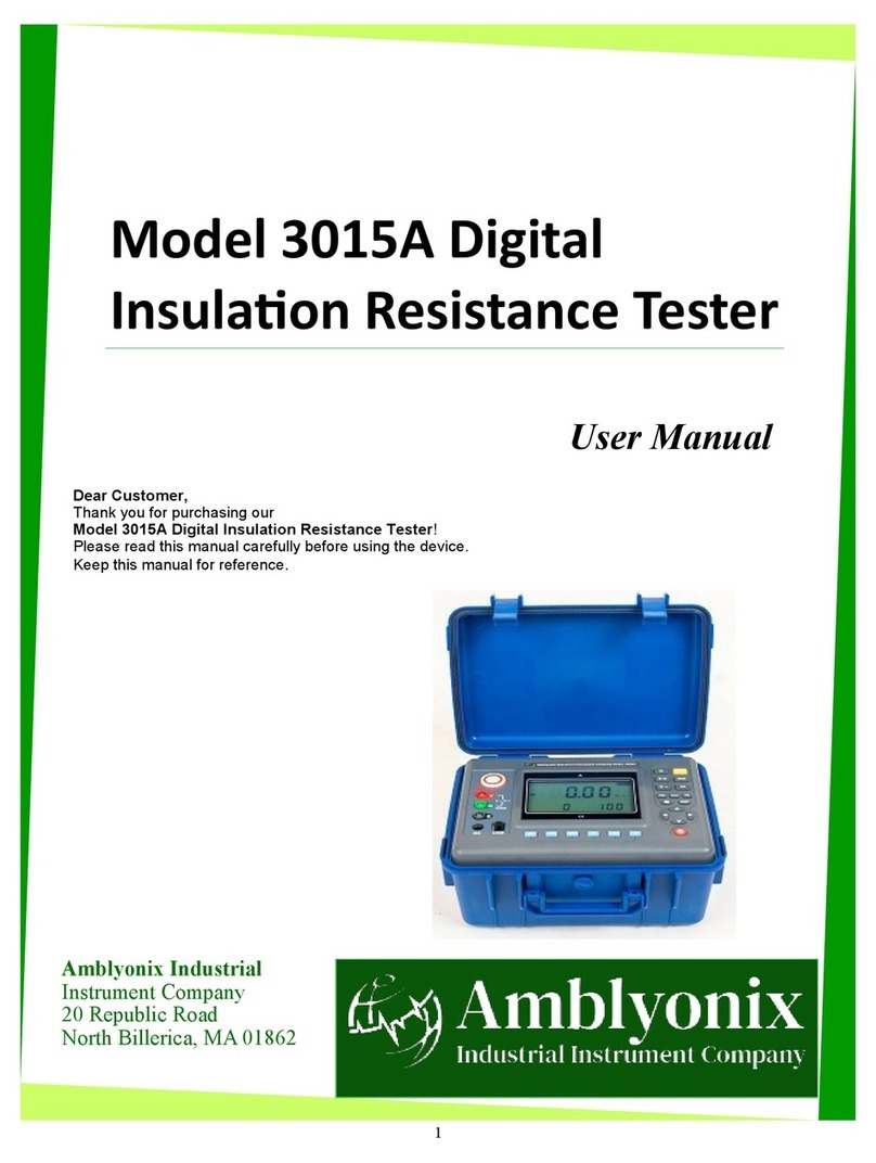
Amblyonix 3005A User manual

1
Model 3005A Digital
Insulaon Resistance Tester
User Manual
Amblyonix Industrial
Instrument Company
20 Republic Road
North Billerica, MA 01862
Dear Customer,
Thank you for purchasing our
Model 3005A Digital Insulation Resistance Tester!
Please read this manual carefully before using the device.
Keep this manual for reference.

2
Table of Contents
Before Using the Device 3
The Model 3005A Digital Insulation Resistance Tester 4
Overview 4
How the Model 3005A Digital Insulation Resistance Tester works 4
Measuring Principle 5
Product Information 5
What’s Included in the Box? 5
Model 3005A Digital Insulation Resistance Tester Structure 6
Model 3005A Digital Insulation Resistance Tester Features 7
Model 3005A Digital Insulation Resistance Tester Technical Specifications 8
Measuring Range and Accuracy 9
Voltage Range and Accuracy 10
Using the Model 3005A Digital Insulation Resistance Tester 11
Switching on the Device 11
Checking the Battery 11
Setting the Backlight 11
Setting the Alarm 12
Saving the Data 12
Reviewing the Data 13
Deleting the Data 13
During the Test Procedures 14
Using the Guard Terminal 14
Test Procedures 15
DC Voltage Test 15
AC Voltage Test 16
Insulation Resistance Test 17
Polarization Index (PI) and Dielectric Absorption Ratio (DAR) Tests 19
PI and DAR Functions 20
PI and DAR Differences 20
PI and DAR Applications 21
After Test Procedures 22
After-Sales Services 23

3
1. Before Using the Device
This manual describes the proper use of the Model 3005A Digital Insulation Resistance Tester.
This device conforms to International Electrotechnical Commission standards (IEC61010) on design,
production, and testing. For your safety, please read and follow the safety instructions and precautions
properly before using this device.
Electrical Safety Symbols
Lightning bolt
Double insulation Caution
This symbol indicates risks
of high voltage, electric
shocks, or live wires.
This symbol indicates that the
device is protected by double
or reinforced insulation.
This symbol indicates a
warning to avoid potential
risk or danger.
IMPORTANT: You must read the instructions whenever the safety symbols appear in the
manual. You must pay attention to the safety symbols on the device.
• You must use this device in accordance with the manual to avoid the risk of danger.
• You must use this device carefully to avoid possible electric shock and personal injury.
• Make sure that this device and accessories are in good condition before use.
* You can only use this device when there are no damaged, exposed wires, or
broken parts in testing cables or insulation layers.
• Make sure to fully insert the connector plugs into the correct interfaces of this device.
• You must not impose over 600V AC or DC voltage between the device and the circuit under test.
• To avoid explosions, you must not use this device in a flammable environment.
• You must not keep or store this device in a place with high temperature, moisture or condensation,
or under direct sunlight.
• You must check the batteries regularly.
* When the screen displays a low battery symbol, charge the battery in a timely
manner to increase the life of the battery.
* You must dispose of used batteries in a specified collection place accordingly.
• You must not disassemble this device without our company’s permission.
* We do not provide any maintenance or replacement warranty for device failure
caused by disassembling equipment without our explicit written authorization.
* We are not responsible for any physical or property damage caused by disassembly
of the equipment without our permission.

4
2. The Model 3005A Digital Insulation
Resistance Tester
The Model 3005A Digital Insulation Resistance Tester is a lightweight and portable megohmmeter
designed for high voltage insulation resistance tests. You can use this device to measure the insulation
resistance of insulating materials, motors, cables, transformers, and electrical installations. This device
gives you real-time results in ohms or megohms that can be stored or exported for future analysis.
It has strong anti-interference and is indispensable for the following:
• Electrical systems
• Electric telecommunications
• Substation testing applications
• Metrology and computer rooms
• Oil fields
• Industrial enterprises
• Electromechanical installation and maintenance
The Model 3005A Digital Insulation Resistance Tester is an industrial tester designed to provide
years of dependable service. This device is powered by an advanced lithium-ion battery and can
perform hundreds of insulation resistance tests from a single charge. It has selectable functions that are
programmable for measuring DC voltage, AC voltage, insulation resistance (IR), polarization index (PI),
and dielectric absorption ratio (DAR).
The insulation resistance (IR) quality of electrical systems deteriorates over time due to environmental
conditions and the presence of electrical and mechanical stress. The performance and life of electrical
systems depend on the insulation conditions. That is why it is vital to check the IR of electrical systems
periodically. The Model 3005A Digital Insulation Resistance Tester generates a high voltage across
the insulator to measure resistance. It safeguards electrical systems from abrupt current leakage in
wires that lead to accidental damage, blown circuits, or electrical shocks.
2.1 Overview
2.2 How the Model 3005A Digital Insulation Resistance
Tester works

5
The Model 3005A Digital Insulation Resistance Tester generates a high voltage (V) that creates
electron flow across the insulator. It measures the flowing current (I) and calculates the insulation
resistance value (R) according to the formula, Resistance = Voltage/Current (R=V/I).
This section shows what’s inside the rugged aluminum case.
• 1 Digital insulation resistance tester
• 1 Red high-voltage test cable
• 2 High voltage test cables
• 1 Monitoring software CD
• 1 USB communication line
• 1 12.6V Battery
• 1 Charger
• User Manual
• Warranty Card
2.2.1 Measuring principle
3. Product Information
3.1 What’s included in the box?

6
3.2 Model 3005A Digital Insulation Resistance
Tester Structure
1. LCD screen
2. LINE terminal
3. V interface
4. GUARD interface
5. EARTH interface
6. Charger terminal
7. USB interface
8. Voltage select button
9. Test button
10. Power on/off button
11. Safety alligator clips
12. Test cables(1 green, 1 black)
13. High voltage banana plug
14. Shielded cable connector
15. High voltage test cable
This section shows the structure of the Model 3005A Digital Insulation Resistance Tester.

7
3.3 Model 3005A Digital Insulation Resistance
Tester Features
This section highlights the features of the Model 3005A Digital Insulation Resistance Tester.
Excellent design
The device is beautiful, upscale, and has a shockproof, dustproof, moisture-proof structure.
It is ultra-lightweight, compact, and portable, but is powerful enough for industrial field use.
Measuring voltage
The device is compatible with different voltage ranges, ranging from 100V to 5000V, depending on
the dielectric strength of the insulation.
Multifunctional
The device is suitable for insulation resistance tests and voltage tests. It can also measure
dielectric absorption ratios and polarization indexes.
Front-panel interactive interface
The device is easy to use with a unique interactive interface that displays easy-to-read
measurements and test routines.
Display mode
The device has a 4- bit large liquid crystal display (LCD) with high resolution.
USB communication interface
The device is equipped with a USB interface and software monitoring that allows uploading
stored data to the computer, saving, and printing.
Communication Line
The device uses one USB communication line.
Data storage
The device is equipped with an onboard memory that can store 500 test results.
Data review
The device has a memory recall (MR) feature that allows the user to review stored data.
Overload warning
The device has an overload warning (OL) feature that warns the user when the measurement
range exceeds the allowable range.
Backlight feature
The screen has a gray backlight feature that is suitable for use in dim places.
Automatic shut-down
The device shuts down automatically after 15 minutes of inactivity.
Alarm feature
The device is designed to alarm when the measured voltage value is greater than the
alarm set value or the insulation resistance value is less than the alarm set value.
Safety Regulations full compliance
The device is equipped with strong anti-interference circuit architecture and is in full
compliance with IEC 61010-1, IEC 1010-2-31, IEC 61557-1,5, IEC60529 (IP54)
pollution grade 2, CAT III 300V.

8
3.4 Model 3005A Digital Insulation Resistance
Technical Specifications
Base conditions 23°C±5°C, below 75%rh
Test voltage ranges 100V, 250V, 500V, 1000V, 2500V, 5000V
Test voltage accuracy (±10%)
Insulation resistance range (GΩ) 0.01 MΩ – 2000 GΩ
Insulation resistance resolution 0.01 MΩ – 1 GΩ
DC voltage range 0 – 1000V
DC voltage range resolution 0.1V
AC voltage range 0 – 750V
AC voltage range resolution 0.1V
Output short-circuit current ≥5mA (5KV)
Power supply 12.6V rechargeable battery
LCD screen size 108mm × 65mm
Instrument size L/W/H: 10.9 ” × 9.0 ” × 6.0 ”
Instrument weight 6.0 lbs (including battery)
Insulation resistance ≥50MΩ (between measuring line and housing)
Voltage withstand AC3kV/60Hz 1 minute
Working temperature and humidity -10°C — +50°C<85%RH
Storage temperature and humidity -15°C — +55°C<90%RH
Test cables
3m red high voltage test cable
1.5m black high voltage test cable
1.5m green high voltage test cable
Standby: 30mA Max (backlight off)
Power consumption Standby: 42mA Max ( backlight on )
Measuring: 300mA Max (backlight off)
This table shows the technical specifications of the Model 3005A Digital Insulation Resistance Tester.

9
3.5 Measuring Range and Accuracy
3.5.1 Insulation Resistance Range and Accuracy
This table shows the output voltage, measuring range, accuracy, and resolution for the insulation
resistance (IR) test.
Test Function Output Voltage Measure Range Accuracy Resolution
100V (±10%)
0 MΩ – 5 MΩ ±5%rdg±5dgt 0.01 MΩ
Insulation
Resistance
5 MΩ – 50 MΩ ±5%rdg±5dgt 0.01 MΩ
50 MΩ – 500 MΩ ±5%rdg±5dgt 0.1 MΩ
0.5 GΩ – 5 GΩ ±10%rdg±5dgt 0.01 GΩ
5 GΩ – 20 GΩ ±10%rdg±5dgt 0.1 GΩ
250V (±10%)
0 MΩ – 10 MΩ ±5%rdg±5dgt 0.01 MΩ
10 MΩ – 100 MΩ ±5%rdg±5dgt 0.1 MΩ
100 MΩ – 1000 MΩ ±5%rdg±5dgt 1 MΩ
1 GΩ – 10 GΩ ±5%rdg±5dgt 0.01 GΩ
10 GΩ – 30 GΩ ±5%rdg±5dgt 0.1 GΩ
500V (±10%)
0 MΩ – 20 MΩ ±5%rdg±5dgt 0.01 MΩ
20 MΩ – 200 MΩ ±5%rdg±5dgt 0.1 MΩ
200 MΩ – 2000 MΩ ±5%rdg±5dgt 1 MΩ
2 GΩ – 20 GΩ ±5%rdg±5dgt 0.01 GΩ
20 GΩ – 50 GΩ ±10%rdg±5dgt 0.1 GΩ
1000V (±10%)
0 MΩ – 50 MΩ ±5%rdg±5dg 0.01 MΩ
50 MΩ – 500 MΩ ±5%rdg±5dg 0.1 MΩ
500 MΩ – 5000 MΩ ±5%rdg±5dg 1 MΩ
5 GΩ – 50 GΩ ±5%rdg±5dg 0.0 1GΩ
50 GΩ – 100 GΩ ±10%rdg±5dg 0.1 GΩ

10
3.5.2 Voltage Range and Accuracy
Test Function Output Voltage Measure Range Accuracy Resolution
2500V (±10%)
0 MΩ – 10 MΩ ±5%rdg±5dgt 0.01 MΩ
Insulation
Resistance
10 MΩ – 100 MΩ ±5%rdg±5dgt 0.1 MΩ
100 MΩ – 1000 MΩ ±5%rdg±5dgt 1 MΩ
1 GΩ – 10 GΩ ±5%rdg±5dgt 0.01 GΩ
10 GΩ – 100 GΩ ±5%rdg±5dgt 0.1 GΩ
100 GΩ – 300 GΩ ±10%rdg±5dgt 1 GΩ
5000V (±10%)
0 MΩ – 20 MΩ ±5%rdg±5dgt 0.01 MΩ
20 MΩ – 200 MΩ ±5%rdg±5dgt 0.1 MΩ
200 MΩ – 2000 MΩ ±5%rdg±5dgt 1 MΩ
2 GΩ – 20 GΩ ±5%rdg±5dgt 0.01 GΩ
20 GΩ – 200 GΩ ±5%rdg±5dgt 0.1 GΩ
200 GΩ – 2000GΩ ±10%rdg±5dgt 1 GΩ
Note: These are the common electrical unit conversions.
1 TΩ(Tera ohm)= 1000 GΩ = 1012Ω
1 GΩ(Giga ohm)= 1000 MΩ = 109Ω
1 MΩ(Mega ohm)= 1000 KΩ = 106Ω
Test Function Measure Range Accuracy Resolution
DC Voltage DC 0.0V — 1000V ±1.5%rdg±3dgt 0.1V
AC Voltage AC 0.0V — 750V ±1.5%rdg±3dgt 0.1V
This table shows the measuring range, accuracy, and resolution for the DC and AC voltage tests.

11
4. Using the Model 3005A Digital Insulation
Resistance Tester
This section provides steps on how to use the Model 3005A Digital Insulation Resistance Tester.
4.1 Switching on the Device
Press to turn the device on.
After turning the device on, Automatic Power Off (APO) appears in the lower corner of the screen.
The device shuts down automatically after 15 minutes of inactivity.
4.2 Checking the Battery
After turning the device on, check the battery level. When the battery is low, the battery indicator
blinks and the backlight turns on and off repeatedly. Charge the battery in a timely manner to ensure
measurement accuracy and to ensure long battery life.
4.3 Setting the Backlight
Press to switch on or switch off the backlight.
Use the backlight function during test procedures in dim places.

12
4.4 Setting the Alarm
1. Press to switch on or switch off the alarm function.
2. Press to set the alarm value setting mode.
3. Press to select the resistance value setting.
4. Press to select DC voltage setting.
5. Press to select AC voltage setting.
6. Scroll through , , , to select the desired value.
7. Press to save and exit.
If… And… Then…
you switched on the
alarm function
the measured voltage value is
greater than the critical set value
The LCD screen flashes
the symbol and emits a
beep-beep-beep alarm sound.
the insulation resistance value is
less than the critical set value
4.5 Saving the Data
1. Press to record the current data after the test.
The LCD screen displays the FULL symbol if the storage is full.
2. Press to save and exit.

13
4.6 Reviewing the Data
1. Press to enter the review data mode.
The LCD screen displays the symbol.
2. Scroll through , , , to select the data that you want to review.
3. Press to save and exit.
Note: If there is no stored data, the LCD screen displays the NULL symbol.
4.7 Deleting the Data
1. In the data review state, press to enter data deletion mode.
2. Press to return to the data review state.
3. Press to delete the stored data.

14
5. During the Test Procedures
This section provides safety instructions during the test in a live working environment.
Please read and follow the instructions properly to ensure safe and proper use of this device.
•You must wear high-voltage insulating gloves during the test procedures.
• You must not use high-frequency signal generators like mobile phones and
others to avoid error when measuring.
• You must not touch the bare conductors and circuits under test.
• You must not use this device when there are damaged, exposed, or broken parts
in testing wires or insulation layers.
• You must not charge batteries or perform data transmission uploads while performing
an insulation resistance measurement.
• You must pay attention to measuring ranges and specific environmental conditions
during the usage of this device.
• You must not use this device when the battery cover is open, especially during
adverse weather conditions.
• This device generates a high voltage. Make sure to connect the test cables properly.
Before pressing the test button, remove your hands from the test cables to avoid
the risk of electric shock.
• When the test is complete, wait for one minute before removing the test cables.
5.1 Using the Guard Terminal
When measuring the insulation resistance of a cable, the leakage current of the cable
surface is in parallel to the current that passes through the interior of the insulation.
Then, the current converges resulting in an error in the insulation resistance value.
To avoid this occurrence, use a protection wire guard to guard the leakage current, as
shown in the figure below. After connecting to the guard terminal, the leakage current
does not flow through the indicator and the insulator accurately measures the insulation
resistance. You must use the guard test cable to connect to the guard terminal.

15
6. Test Procedures
This section provides important instructions on how to perform DC voltage, AC voltage, insulation resistance
(IR), polarization index (PI), and dielectric absorption ratio (DAR) tests.
6.1 DC Voltage Test
The input DC voltage must not exceed 1000V.
1. Press to turn the device on.
2. Press to switch to DC voltage test mode.
3. Connect the green connector plug into the interface and then connect the safety alligator clip
to the unit under test.
4. Connect the black connector plug into the interface, and then connect the safety alligator clip
to the unit under test.
The LCD screen displays the real-time DC voltage value.

16
6.2 AC Voltage Test
The input AC voltage must not exceed 750V.
1. Press to turn the device on.
2. Press to switch to AC voltage test mode.
3. Connect the green connector plug into the interface and then connect the safety alligator clip
to the unit under test.
4. Connect the black connector plug into the interface, and then connect the safety alligator clip
to the unit under test.
The LCD screen displays the real-time AC voltage value.

17
6.3 Insulation Resistance Test
• You can only perform insulation resistance tests on non-energized circuits.
• Before the insulation resistance test, check if the test circuit wiring is in good
condition and if the circuit under test is energized. An energized circuit can
damage the instrument and affect measurement accuracy.
• Make sure to connect the black grounding wire to the grounding port of the
circuit under test.
• After the test, do not touch the circuit immediately. Wait until the discharge is
complete before touching the circuit; stored charge can cause electric shock.
• To ensure measurement accuracy, do not twist the test cables together.
The table shows the guaranteed temperature and humidity of the insulation resistance accuracy.
Insulation resistance
range
Guaranteed humidity value
of the insulation resistance
Guaranteed temperature
of the insulation
resistance accuracy
0 Ω – 100 MΩ
<85% RH (No condensation)
23°C±5°C
101 MΩ – 20 GΩ
<75% RH (No condensation)
21 GΩ – 1000 GΩ
<65% RH (No condensation)

18
1. Press to start.
2. Press , or , or , or , or , or to select the voltage value.
3. Connect the black connector plug into the interface, and then connect the safety alligator clip
to the grounding port of the circuit under test.
4. Connect the banana plug of the red high voltage test cable into the terminal, and then connect
the high-voltage probe to the circuit under test.
5. Connect the shielded cable connector into the interface.
6. Press to start the test.
The device emits an audible beep during testing.
The LCD screen displays the real-time insulation resistance value.
7. After the measurement is complete, press to record the current display data.
The device saves the measured display data in storage automatically.

19
6.4 Polarization Index (PI) and Dielectric Absorption Ratio
(DAR) Tests
• You can only perform PI and DAR tests on uncharged circuits.
• Before the test, check if the test circuit wiring is in good condition and if the circuit
under test is energized.
1. Press to start.
2. Press , or , or , or , or , or to select the voltage value.
3. Press to set the corresponding mode.
The LCD displays
• 10:01m - polarization index mode,
• 60:15S - absorption mode 15-second mode, and
• 60:30S - absorption mode 30-second mode.
The LCD does not display small values for the insulation resistance measurement mode.
Polarization index mode
Absorption ratio 15 seconds mode Absorption ratio 30 seconds mode
4. Connect the black connector plug into the interface, and then connect the safety
alligator clip to the grounding port of the circuit under test.
5. Connect the banana plug of the red high voltage test line into the terminal, and then
connect the high-voltage probe to the circuit under test.
5. Press to start the test.
The LCD displays the real-time PI and DAR values.
7. Press to view the divisor of the DAR or PI value, the value of 60 in “60:15S” mode.
8. Press to view the dividend of the DAR or PI value, the value of 15 in “60:15S” mode.
9. Press or to return.

20
6.4.1 Polarization Index (PI) and Dielectric Absorption Ratio
(DAR) Functions
The Model 3005A Digital Insulation Resistance Tester automatically calculates the PI and DAR values.
The function of the PI and DAR tests is to check if the leakage current of the insulator has increased.
The results indicate the change in insulation resistance after the measured circuit withstands the
measured voltage.
6.4.2 Polarization Index (PI) and Dielectric Absorption Ratio
(DAR) Differences
DAR refers to the short-term IR test that you can perform to increase the leakage current while the applied
voltage polarizes the atoms in the insulation. You can measure the IR when the leakage current stabilizes
within one minute. DAR test is suitable for general insulation testing such as house wiring insulation, tool
handles, and other equipment which can be tested in a short time. You can perform a PI test when DAR is
not enough to reflect the long-term process of absorption. PI test is suitable for insulation with higher index
or large capacities such as transformers, generators, cables, and other electrical equipment. The ratio
between the insulation resistance (R10min) at 10 minutes and the insulation resistance (R1min) at
one minute describes the entire process of insulation absorption.
Polarization Index
R 10 Min
R 1 Min
R10Min = resistance value measured by the
voltage applied for 10 minutes
R1Min, R60Sec = resistance value
measured by the voltage applied for
1 minute
R15Sec = resistance value measured by
the voltage applied for 15 seconds
Absorption Ratio
R 60 Sec
R 15 Sec
Absorption Ratio
R 60 Sec
R 30 Sec
R30Sec = resistance value measured by
the voltage applied for 30 seconds
The Model 3005A Digital Insulation Resistance Tester calculates the PI and DAR values by:
Note: You can select between 15 seconds and 30 seconds DAR calculation
time, depending on the index capacity of the circuit under test.
Table of contents
Other Amblyonix Test Equipment manuals