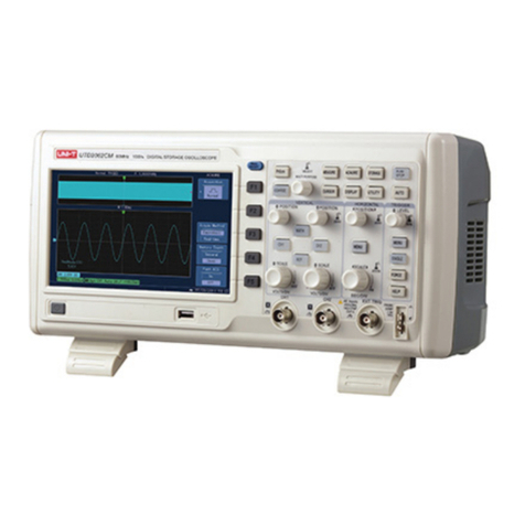
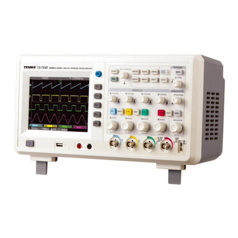
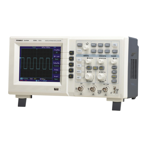
Tenma 72-2650 User manual

72-2650
72-8705A
72-8710A
72-8225A
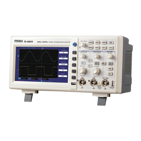
72-10510
P/N: 110401105556X REV.0 DATE:2016-02-20

If you have read through the manual, it is recommended that you keep it safe along with the instrument, or in a
place where it is easily accessible, should you require the information for future usages.
,,

72-2650/72-10510/72-8225A /72-8705A/72-8710A user manual

General Safety Overview
The instrument is designed and manufactured under
the safety requirement for GB4793 electric measuring
instrument and IEC61010-1 safety standards. It conforms
to insulation overvoltage standards CATII and safety
standards of pollution level II. The following safety
measures are set out to help avoid any personal injury or
product damage, or damage to any products that connect
with the instrument.
In order to avoid any potential
hazards, please be
sure to use the product as stipulated.
Ensure personnel receive training before using
the product.
Use correct power line: Only the dedicated power
lines for
the product recognized by host country can be
adopted.
Correctplugging and unplugging: Do not plug in
or unplug the unit while probes or testing leads are
connected to a voltage source.
Product grounding: The ground lead of power supply.
In order to avoid electric shock, the ground connection
must not be circumvented. Prior to connectingthe
input or output terminal of the product, ensure the
product is grounded correctly.
Correctly connect the oscilloscope probe: The probe
ground lead and the ground are of the same potential.
Do not connect the ground lead with high voltage.
Check the rated values of all terminals: Check all
rated values and marking on the product match local
supply to avoid fire damage or electrical shock; check
the product manual before connecting the product to
view information on the rated values.
Do not open the cover plate of the case during operation:
Do not turn on or operate the product when the external
cover or panel is opened.
Use a proper fuse: Only fuse types and rated indexes
designated for the product.
Avoid circuit exposure: Do not contact exposed contact
or elements after powering on.
72-2650/72-10510/72-8225A /72-8705A/72-8710A user manual
Do not operate the product if it is suspected to
be malfunctioning: Seek qualified maintenance
personnel for inspection.
Ensure proper ventilation.
Do not operate in a humid environment.
Do not operatein an inflammable and explosive
environment.
Keep the surface of the product clean and dry.
Safety terms and symbols
The following terms may be present in the manual:
Warning: warning statements indicate conditions
and actions that may endanger life.
Attention: attention statements indicate conditions
and actions that may cause damages to the
product and other properties.
Hazard: Indicates there is direct damage hazard close
to the marking.
Warning: Indicates there is potential damage hazard
close to the marking.
Attention: Indicates there is potential hazard to the
product and other properties.
Symbols on the product: Such symbols may appear
on the product.
High voltage Please refer to
the manual
Protective
ground terminal
Shall ground
terminal
Measuring
ground terminal
72-2650/72-10510/72-8225A /72-8705A/72-8710A user manual

The Manual introduces information related to the operation of digital storage oscilloscopes 72-2650/72-10510/
72-8225A
/72-8705A/72-8710A. The manual comprises the following chapters:
Chapter I Introduction
Chapter II Instrument Setting
Chapter III System Message Example and Troubleshooting
Chapter IV Service and Support
Chapter V Technical Indexes
Appendix A: Technical Specification
Appendix B: Accessories of 72-2650/72-10510/72-8225A /72-8705A/72-8710A
Appendix C: Maintenance and Cleaning Maintenance
Appendix D: Chinese and English Panel Comparison Table
Preface
This user manual covers the following five models of DSO as shown in the table below:
Model Bandwidth Real-time Sampling Rate
72-2650
72-10510
200MHz
100MHz
50MHz
50MHz
25MHz
1GS/s
1GS/s
1GS/s
250MS/s
500MS/s
72-8710A
72-8705A
72-8225A
72-2650/72-10510/72-8225A /72-8705A/72-8710A user manual

72-2650/72-10510/72-8225A /72-8705A/72-8710A
provide the users with simple operation andclear
functions to perform all the basic operations. Scale and
position knobs of each channel provide intuitive,controls
and use. In order to accelerate adjustment and facilitate
measurement, the users can press the AUTO key and
the instrument will then display applicable waveform and
gear position settings.
Apart from easy to use,72-2650/72-10510/72-8225A/
72-8705A/72-8710A DSO also has high performance
indexes and powerful functions required for faster
completion of measurement tasks. Faster signals can
be observed on 250MS/s (72-1050) or 500MS/s (72-10510)
or 1GS/s (72-8705A/72-8710A/72-2650) equivalent
sampling. Powerful trigger and analysis ability make it
easier to capture and analyse waveforms. Clear LCD
and mathematical operation functions make it easier for
users to observe and analyse signal problems in a faster
and clearer way.
From the following parameter features, you can
understand how this series of DSO can satisfy your
measurement requirements.
● Two analog channels.
●
High resolution LCD display
resolution:
72-2650: 320×240
72-1050/72-10510:400×240
72-8705A/72-8710A:800x400
●
Support plug and play USB storage equipment and
be capable of communicating with computer via USB
storage equipment.
● Automatic waveform and state settings.
● Waveform saving and replay feature.
●
Delicate window extension function and precise
analysis on waveform details and overview.
●
Automatic measurement of 28 waveform parameters.
● Automatic cursor tracking measurement function.
●
Unique functions of waveform recording and playback.
● Built-in FFT software function.
72-2650/72-10510/72-8225A /72-8705A/72-8710A user manual
●
Multi-waveform mathematical operation function
(including: addition, subtraction, multiplication and
division).
●
Edge, video, pulse width, alternating trigger and other
functions .
● Multi-language menu selection.
●
Simplified Chinese and English help information
display.
Accessories of 72-2650/72-10510/72-8225A/72-8705A/
72-8710A DSO
● Two of probes with 1:1/10:1 X selection.
● One power line.
● One User Manual .
● USB cable.
●
Oscilloscope communication
control software CD.
72-2650/72-10510/72-8225A /72-8705A/72-8710A user manual

Chapter I Introductions ------------------------------------------------------------------------------------------------------------------ 1
1.1 Get to know the User Interface ----------------------------------------------------------------------------------------------------- 1
1.2 General Inspection --------------------------------------------------------------------------------------------------------------------- 5
1.3 Function Inspection -------------------------------------------------------------------------------------------------------------------- 5
1.4 Probe Compensation ------------------------------------------------------------------------------------------------------------------ 7
1.5 Automatic Settings of Waveform Display ----------------------------------------------------------------------------------------- 8
1.6 Introduction to The Vertical System ------------------------------------------------------------------------------------------------ 9
1.7 Introduction to The Horizontal System -------------------------------------------------------------------------------------------- 10
1.8 Introduction to The Trigger System ------------------------------------------------------------------------------------------------ 11
Chapter II Instrument Settings ------------------------------------------------------------------------------------------------------- 12
2.1 Set The Vertical System -------------------------------------------------------------------------------------------------------------- 12
2.2 Set The Horizontal System ---------------------------------------------------------------------------------------------------------- 12
2.3 Set The Trigger System -------------------------------------------------------------------------------------------------------------- 21
2.4 Set the Acquire System -------------------------------------------------------------------------------------------------------------- 24
2.5 Set The Display System ------------------------------------------------------------------------------------------------------------- 31
2.6 Set The Storage and Load System ----------------------------------------------------------------------------------------------- 35
2.7 Set The Utility System --------------------------------------------------------------------------------------------------------------- 41
72-2650/72-10510/72-8225A /72-8705A/72-8710A user manual

2.8 Set The Measurement Parameters ---------------------------------------------------------------------------------------------- 44
2.9 Set The Cursor Measurement ----------------------------------------------------------------------------------------------------- 46
Chapter III System Message Example and Troubleshooting -------------------------------------------------------------- 47
Chapter IV Technical Information --------------------------------------------------------------------------------------------------- 50
Appendix A: Technical Specification ---------------------------------------------------------------------------------------------- 50
Appendix B: Accessories of 72-2650/72-10510/72-8225A /72-8705A/72-8710A DSO ------------------------------ 68
Appendix C: Maintenance and Cleaning Maintenance ---------------------------------------------------------------------- 68
72-2650/72-10510/72-8225A /72-8705A/72-8710A user manual
Chapter I Introductions
72-2650/72-10510/72-8225A /72-8705A/72-8710A
DSO is desk type DSO. It is designed with conventional
user interface design for intuitive DSO usage for
testing and measurement. This chapter will cover the
following as the beginner guide to the 72-2650/72-10510
/72-8225A/72-8705A/ 72-8710A DSO:
△1.1 Get to know the User Interface
△1.2 General inspection
△ 1.3 Functional inspection
△ 1.4 Probe compensation
△ 1.5 Automatic settings of waveform display
△ 1.6 Introduction to the vertical system
△1.7 Introduction to the horizontal system
△1.8 Introduction to the trigger system
1.1 Get to know the User Interface
Gaining familiarity with the different parts of the user
interface of the 72-2650/72-10510/72-8225A /72-8705A/
72-8710A DSO is important for use and the operation
of the DSO. The user interface of 72-2650/72-10510/
72-8225A /72-8705A/72-8710A DSO consist of:
● Vertical control
● Horizontal control
● Trigger control
● LCD display area
● Function buttons (F1, F2, F3, F4, F5)
● User menu area
● Input terminal (CH1, CH2, EXT TRIG)
● Multi-purpose knob
● USB interface
72-2650/72-10510/72-8225A /72-8705A/72-8710A
DSO are shown on the figure 1-1 and figure 1-2.
1
72-2650/72-10510/72-8225A /72-8705A/72-8710A user manual

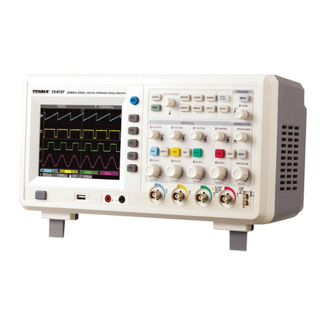
72-2650 200
Figure 1-1: 72-2650 DSO Panel Diagram - 5.7-inch TFT color LCD display
2
72-2650/72-10510/72-8225A /72-8705A/72-8710A user manual

72-10510
Figure 1-2: 72-10510/72-8225A/72-8705A/72-8710A DSO Panel Diagram -7-inch TFT color LCD display
3
72-2650/72-10510/72-8225A /72-8705A/72-8710A user manual
DSO User Interface Menu Display (72-10510 pictured)
4
72-2650/72-10510/72-8225A /72-8705A/72-8710A user manual
1.2 General Inspection
After purchasing a new 72-2650/72-10510/
72-8225A /
72-8705A/72-8710A DSO, we recommend you to inspect
the instrument according to the following steps.
1. Inspect whether there is any damage caused
by
transit.
In case of damage to the packing box or foamed plastic
packaging materials, contact your point of purchase.
2. Accessories inspection.
For provided accessories details, description has been
made in aforesaid “accessories of 72-2650/72-10510/
72-8225A /72-8705A/72-8710A DSO” item of this user
manual. Please check whether there are any
accessories missing. If any of the items are missing
or damaged please contact your point of purchase.
3. Check the complete instrument.
In case of damages to the appearance of the instrument,
abnormal operation or failure to pass the performance
tests, please contact the Tenma product distributors or
local Tenma offices.
If the instrument is damaged due to transportation, please
pay attention to keeping the package, notify transportation
department and Tenma product distributors and Tenma
will make arrangement for repair or replacement.
Warning: Please ensure that the DSO has been safely
grounded to avoid hazard.
1.3 Function Inspection
Conduct a fast function inspection to verify whether
the instrument is in normal operation. Please take the
following steps:
Power on the instrument
Power on the instrument with a voltage supply of AC
100 to 240VAC and frequency of 45 to 440Hz.
After
powering on, press UTILITY menu and wait for
30min, and then press F1 auto calibration. At the next
menu level, press the F1 button again at the “factory settings”
as shown in Figure 1-4.
5
72-2650/72-10510/72-8225A /72-8705A/72-8710A user manual

72-10510
Warning: please confirm that the DSO has been safely
grounded to avoid hazard.
DSO accessing to signal
①. 72-2650/72-10510/72-8225A /72-8705A/72-8710A
DSO has two input channels with an additional external
trigger input channel. Please check the signal according
to the following steps. Connect DSO probe to CH1 input
terminal and set the attenuation rate switch on the probe
as 10× (Figure 1-5)
Figure 1-5 Setting of Probe Attenuation Rate Switch
②.
It is necessary to set probe attenuation coefficient on DSO.
Attenuation coefficient changes the vertical gear position
rate of the instrument, thus making the measurement result
correctly reflect the amplitude of measured signals. Probe
attenuation coefficients are set in the following ways:
6
72-2650/72-10510/72-8225A /72-8705A/72-8710A user manual
Press F4 to make the menu display 10×
Figure 1-6 Setting of attenuation coefficient on DSO
③. Connect the probe pin and ground clamp to the
corresponding terminal of the probe compensation signal.
Press AUTO key. Within several seconds, square wave
display (1kHz, about 3V, peak-to-peak value) is as shown
in Figure 1-7. Check CH2 in the same way; press OFF
function key to close CH1; press CH2 function key to
turn on CH2; repeat step 2 and step 3.
Figure 1-7 Probe Compensation Signal
1.4 Probe Compensation
When connecting the probe with any input channel for
the first time, it is required to make the adjustment each,
matching the probe with input channel. Probe use
without compensation will lead to measurement error.
In case of probe compensation, follow the following
7
72-2650/72-10510/72-8225A /72-8705A/72-8710A user manual
steps:
1. Set the probe menu attenuation coefficient as 10×,
place the switch on the probe at 10× and connect the DSO
probe with CH1. Connect the probe end and signal
output connector to the probe compensator, the ground
clamp and ground lead connector of the probe
compensator,
turn on CH1 and press
AUTO .
2. Observe displayed waveform
Over-
compensation
Correct
compensation
Under-
compensation
Figure 1-8a Probe Compensation and Correction
If the screen displays “under-compensation” or “over-compensation”
for waveform as shown in the above figures, use a screwdriver
with a nonmetal handle to adjust the variable capacitance
on the probe until the screen displays “correct compensation”
for the waveform as shown in the below figure.
Figure1-8b:Correct compensation
Warning: In order to avoid electric shock when
measuring high voltage with the probe, please ensure that
the insulation lead of the probe is in good condition and
do not touch the metal part of the probe when
connected to a high voltage power supply.
1.5 Automatic Settings of Waveform Display
72-2650/72-10510/72-8225A /72-8705A/72-8710A
DSO has automatic setting function. According to input
signals, the DSO automatically adjusts the
vertical
deflection factor, scanning time base and trigger
mode
until the most appropriate waveform is displayed.
To apply the automatic setting, the frequency of the measured
signal is required to be ≥ 50Hz and the duty ratio is > 1%.
8
72-2650/72-10510/72-8225A /72-8705A/72-8710A user manual

Apply automatic setting
1. Connect the measured signal to the signal input channel.
2. Press AUTO key. DSO will automatically set its vertical
deflection factor, scanning time base and trigger mode.
If further careful observation is required, adjustment can
be conducted again after automatic settings until the
waveform display reaches the required optimum effect.
1.6 Introduction to The Vertical System
As shown in the figure below, there are a series of keys
and knobs in the vertical control area. The instructions
below
will guide you with controlling
the vertical system.
72-2650 vertical
control panel (Left)
72-10510/72-8225A
/72-8705A/72-8710 A
vertical control panel
(Right)
Figure 1-9 Vertical Control Area on the Panel
1. Use the vertical position knob to move the vertical
position of the waveform display on the LCD screen. By
default, the waveform should be displayed at the centre of
the screen.
2. should see the waveform move vertically
upward and downward when the knob is rotated.
3. The user can also change the waveform scale by rotating
the Scale Knob on the vertical system. Please notice that
the “V/div” will be changed to indicate the corresponding
vertical scale level.
4. The user can enable/disable the input channel by pressing
the [CH1] and [CH2] button on the vertical system
(For 72-10510/72-8225A/72-8705A/72-8710A
DSO).
Attention:
To disable the input channel for the 72-2650 DSO,
please press the [OFF] button on the vertical system.
All of the other vertical system settings will be
explained in greater detail in chapter II of this user
manual.
9
72-2650/72-10510/72-8225A /72-8705A/72-8710A user manual
The user

1.7 Introduction to The Horizontal System
As shown in the figure below, there is one key and
two knobs within the horizontal control area. The
instructions
below will guide you with setting the
horizontal
time base.
72-2650 horizontal
control panel (Left)
72-10510/72-8225A/
72-8705A/72-8710A
horizontal control
panel (Right)
Figure 1-10 Horizontal Control Area on the Panel
1. Use the horizontal SCALE knob to change the gear
position
settings of the horizontal time base and observe
the changes
of state information. Turn the horizontal
SCALE knob to change the "s/div" time base gear
position, and you can find
that corresponding changes
have taken place in the time
base gear position display
of the corresponding channel in
the status bar.
Horizontal scanning rate steps up in multiples of
1,2 and then 5 , e.g. 1ms/div->2ms/div->5ms/div-
>10ms/div…. etc.
*Note: the horizontal time base range of different
72-2650/72-10510/72-8225A /72-8705A/72-8710A
varies between 2ns/div to 50s/div.
Details are listed in
technical specification.
2.
Use the horizontal POSITION knob to adjust the horizontal
position of the signal in the waveform window. The horizontal
POSITION knob controls the trigger position of the input
signal. When applying to trigger position and turning
the horizontal POSITION knob, it is possible to observe
the
horizontal movement of the waveform along with
POSITION knob turning.
10
72-2650/72-10510/72-8225A /72-8705A/72-8710A user manual
Other manuals for 72-2650
1
This manual suits for next models
4
Table of contents
Other Tenma Test Equipment manuals

Tenma
Tenma 72-2680 User manual

Tenma
Tenma TEN01057 User manual

Tenma
Tenma 72-6802 User manual

Tenma
Tenma 72-6694 User manual

Tenma
Tenma 72-9405 User manual

Tenma
Tenma 72-9966 User manual

Tenma
Tenma 72-3575 User manual

Tenma
Tenma 72-7615 User manual

Tenma
Tenma 72-14520 User manual

Tenma
Tenma 72-3565 User manual