BASEWEST TS-421 User manual

BASEWEST
Operating Manual
Model TS-421 Test Set
Escape Slide Lighting Systems
Released
December 21, 2023
BaseWest Inc.
4240 116
th
Ave N, Clearwater, FL 33762
Tel: 727 / 573-2700 • Fax: 727 / 573-4307
E-mail: info@basewest.com
www.basewest.com
25-60-45

BASEWEST
Operating & Maintenance Manual
Model TS-421 Test Set
Page 2 of 8
25-60-45
21 December 2023
1.0 General
1.1 Introduction
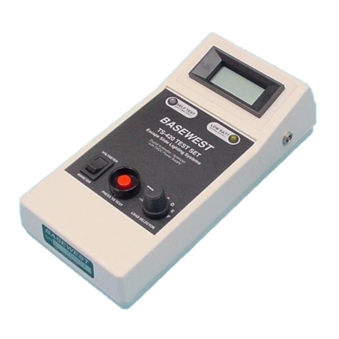
The Model TS-421 test set is a rechargeable, handheld instrument designed for testing
airline escape slide lighting systems, light harnesses and batteries. The test set includes a
voltmeter and ammeter with touchscreen operation, a built-in rechargeable battery, a
5VDC power supply and a removable protective cover. The unit is provided with a 120/220
VAC charger and adapter for both domestic and international use. The TS-421 replaces
the original TS-420 test set which is inactive for procurement and duplicates the functions
of the Astronics TU-14 test set.
TS-421 Test Set (Home Screen Shown)
1.2 Function
The Model TS-421 provides the following test modes selectable at the Home Screen:
• Voltmeter Mode with built-in load bank – The Voltmeter Mode is used to test the
condition of the slide lighting system battery. A touchscreen interface provides for the
selection of resistive loads including an open circuit (no load) test. Testing is initiated
with the RED press-to-test button.
• Ammeter Mode with regulated power supply – The Ammeter Mode verifies the
electrical current draw of the slide light harness with power supplied by the test set’s
internal 5 VDC / 3A power supply. This test provides a built-in 30 second timer that
allows a hands-free walk-around to visually confirm luminaire operation. Testing is
initiated with the RED press-to-test button.
1.3 Test Connections
Test connections are made at the connector block on the top of the instrument, shown in
the following image. These connections include a 4-contact receptacle to mate with the

BASEWEST
Operating & Maintenance Manual
Model TS-421 Test Set
Page 3 of 8
25-60-45
21 December 2023
test lead of the slide light battery and polarized contacts to test individual light harnesses.
Marked polarity must be observed when testing individual LED-based harnesses.
Test Connections / Connector Block
1.4 Test Set Activation
The TS-421 is OFF when the Touchscreen is dark and the RED button is not illuminated.
The test set is turned ON by pressing the RED button. The HOME screen appears with
Voltmeter or Ammeter test selection options, shown center, below.
Inactive / OFF HOME Screen Charging Required
If the internal battery is not sufficiently charged for test set operation, the screen to the
right, above will appear for 3 seconds, indicating that recharging is required. The test set
will then turn OFF.
1.5 Home Icon
The HOME screen reappears at any time the HOME icon, shown below, is pressed.
.
Polarized Contacts
for Individual Light
H
arness
Connection
4-Contact Receptacle for
Battery or System Testing
through Battery Test Lead

BASEWEST
Operating & Maintenance Manual
Model TS-421 Test Set
Page 4 of 8
25-60-45
21 December 2023
1.6 Internal Battery Status
The charge status of the test set’s internal battery is monitored and displayed upon
activation of the test set and whenever the touchscreen is active. The battery status icon is
displayed in the top righthand corner of the screen indicating state of charge. When the
internal battery voltage goes lower than a predetermined level, the icon will change from
Green to Yellow indicating that the unit can be used but should be recharged before next
usage.
Half Charge (Yellow) Full Charge (Green)
1.7 Recharging
Recharging of the internal battery is accomplished with the P/N 36-1019 120/220 VAC
charger provided with the unit. Chargers provided with the earlier TS-420 test set may
continue to be used with the TS-421. The recharging port is located at the lower right-hand
side of the test set. A recharging time of at least overnight is recommended.
1.8 Display Timing
Voltmeter and ammeter test readings remain on the screen for 30 seconds. After 30
seconds, the screen goes dark and the RED button begins to blink for 90 seconds in the
Voltmeter mode and 120 seconds in the Ammeter mode. While the RED button is
blinking, the last test reading can be recovered by either pressing the RED button or the
touchscreen.
1.9 Automatic Time-Outs
If the test set is left ON and unattended for 90 seconds, the unit will automatically turn
OFF, erasing the last reading. The unit can be manually turned OFF by returning to the
Home screen and pressing the RED button or by holding the RED button for 3 seconds.
2.0 Voltmeter Mode (Battery Testing)
2.1 Connect the 4-contact test lead of the battery under test to the mating receptacle on the
connector block. Note that the connector is keyed for proper alignment.
2.2 Turn the test set ON by pressing the RED button. Press the VOLTMETER icon on the
HOME screen, and the load selection screen appears per figures below.

BASEWEST
Operating & Maintenance Manual
Model TS-421 Test Set
Page 5 of 8
25-60-45
21 December 2023
NOTE: If the battery under test is not connected, or connected improperly, pressing the
RED button creates a three-pulse vibration, and a “Check Connection” prompt appears.
2.3 Select the resistive load specified by the slide manufacturer’s CMM by scrolling through
the loads with the left and right arrows shown in the Select Load figure, below.
Select Voltmeter Mode Select Load
2.4 Once the proper load is selected, press the RED button to initiate the test. A loading icon
appears momentarily until the voltage reading is presented.
Press to Test Test In Process Voltage Reading
2.5 The test reading remains visible for 30 seconds after which the screen goes dark and the
RED button begins to flash for 90 seconds. The test reading can be retrieved while the
RED button is flashing by either pressing the RED button or the touchscreen.

BASEWEST
Operating & Maintenance Manual
Model TS-421 Test Set
Page 6 of 8
25-60-45
21 December 2023
3.0 Ammeter Mode (Light Harness Testing)
3.1 Connect a light harness to the test set in one of two ways:
•If testing an individual lighting harness - Connect lighting harness directly to two
polarized contact pins in the connector block. Be sure to observe polarity; in most
cases the BLUE wire is positive (+) and the WHITE wire is negative (-).
•If testing a lighting harness system while connected to a battery - Connect the
4-contact test lead of the battery to the mating 4-contact receptacle on the
connector block.
3.2 Turn the test set ON by pressing the RED button. Press the AMMETER icon on the HOME
screen, and the ammeter screen appears.
3.3 To initiate the ammeter test, press the RED button. The RED button illuminates, and a
loading icon appears for three seconds until the ammeter reading is presented.
NOTE: If the lighting harness is not connected, connected improperly or the load is very
small (such loads as present during “Gage Tests”), pressing the RED button creates a
three-pulse vibration, and a “Very Small or No Load Check Connection” prompt appears.
Select Ammeter Mode Press to Test Ammeter Reading
3.4 The connected lighting harness will remain illuminated for 30 seconds, allowing the test
operator to conduct a walk-around, hands free, to verify that all luminaires are operating.
3.5 After the lighting harness is turned OFF, the test reading remains visible for an additional
30 seconds. At that point the test screen goes dark and the RED button flashes for 120
seconds. The test reading can be retrieved while the RED button is flashing by either
pressing the RED button or the touchscreen.

BASEWEST
Operating & Maintenance Manual
Model TS-421 Test Set
Page 7 of 8
25-60-45
21 December 2023
4.0 Care & Maintenance
4.1 The TS-421 test set is a sensitive electronic instrument and should be handled with
appropriate care. Damage from obvious abuse cannot be covered by warranty.
•Be particularly careful to protect the touchscreen from any physical damage
(damage to the touchscreen is not covered by warranty).
•The enclosure is not completely sealed; keep the test set away from rain, spills,
and fluids to prevent damage to internal electronics.
•Do not apply external electrical inputs other than the P/N 36-1019 AC charger.
Prior chargers 36-1002, 36-1005 can be used.
•Protect from extreme temperatures and humidity; it is best to store the instrument
in temperature-controlled spaces.
•It is recommended to keep the protective cover in place at all times except for
battery replacement. (Note: the back of the protective cover is provided with a
rotating stand that can be removed if it is not useful.)
•Avoid excessive exposure to sunlight and UV radiation.
4.2 Maintenance is limited to wiping the unit enclosure and touchscreen down lightly with a
clean cloth moistened with alcohol. DO NOT use cleaners or solvents.
4.3 Field repairs except battery replacement are not authorized and will void warranty.
4.4 The replaceable P/N 6-1036 NiMH rechargeable battery is part of the back panel of the
test set enclosure and is replaced together. The battery is on-condition and has an
expected 5 to 7 year life. The battery should be replaced when the charge retention level
becomes unacceptable. Battery replacement can be accomplished at any time without
affecting calibration. Replacement is accomplished as follows:
•Remove protective cover.
•Remove back panel/battery assembly of the test set; retain 4 attach screws.
•Disconnect the battery connection to the test set and discard the old back
panel/battery assembly.
•Connect new the battery connection on the replacement back panel/battery
assembly with same orientation.
•Secure new back panel/battery assembly with four attach screws.
4.5 The unit is provided with a P/N 36-1012 two-prong European-type adapter to mate with
the 36-1019 AC Charger. Other adapters may be used so long as the input voltage is
either 110/120 or 220/240 VAC.

BASEWEST
Operating & Maintenance Manual
Model TS-421 Test Set
Page 8 of 8
25-60-45
21 December 2023
5.0 Calibration
5.1 The BaseWest calibration manual, 25-60-46, is provided with each new unit, and is
available on the BaseWest website under “Resources”. Calibration is recommended at
one-year cycles but is dependent on user requirements and policy. Calibration can be
accomplished without opening the test set enclosure. See the calibration manual for
recommended calibration accessories.
5.2 If the TS-421 test set returned to BaseWest for calibration, it is first inspected for proper
form, fit and function and remaining battery life. Any repairs or replacements needed are
coordinated with the customer prior to calibration. NIST calibration is conducted by a local
NIST-certified calibration house and calibration sticker affixed. The test set is then
returned to BaseWest where it undergoes a final inspection before return to the customer
along with calibration paperwork and any accessories that were sent with the unit.
6.0 Accessories
The following accessories are provided with the TS-421 unit but can be procured
separately, as required.
•P/N 36-1002 – 120/220VAC Charger
•P/N 36-1012 – 120 to 220VAC Adapter, Two-Prong
•P/N 6-1036 – Battery, NiMH, 12VDC
•P/N 52-1027-4 – Protective Cover
Other manuals for TS-421
4
Table of contents
Other BASEWEST Test Equipment manuals
